EP2195488B1 - Verbindung von führungsschienen - Google Patents
Verbindung von führungsschienen Download PDFInfo
- Publication number
- EP2195488B1 EP2195488B1 EP08803676A EP08803676A EP2195488B1 EP 2195488 B1 EP2195488 B1 EP 2195488B1 EP 08803676 A EP08803676 A EP 08803676A EP 08803676 A EP08803676 A EP 08803676A EP 2195488 B1 EP2195488 B1 EP 2195488B1
- Authority
- EP
- European Patent Office
- Prior art keywords
- profile
- holes
- rail
- connecting element
- pattern
- Prior art date
- Legal status (The legal status is an assumption and is not a legal conclusion. Google has not performed a legal analysis and makes no representation as to the accuracy of the status listed.)
- Active
Links
Images


Classifications
-
- E—FIXED CONSTRUCTIONS
- E01—CONSTRUCTION OF ROADS, RAILWAYS, OR BRIDGES
- E01B—PERMANENT WAY; PERMANENT-WAY TOOLS; MACHINES FOR MAKING RAILWAYS OF ALL KINDS
- E01B25/00—Tracks for special kinds of railways
- E01B25/02—Tracks for rack railways
- E01B25/04—Rack rails; Supports or connections for rack rails
-
- B—PERFORMING OPERATIONS; TRANSPORTING
- B66—HOISTING; LIFTING; HAULING
- B66B—ELEVATORS; ESCALATORS OR MOVING WALKWAYS
- B66B7/00—Other common features of elevators
- B66B7/02—Guideways; Guides
- B66B7/022—Guideways; Guides with a special shape
-
- E—FIXED CONSTRUCTIONS
- E04—BUILDING
- E04C—STRUCTURAL ELEMENTS; BUILDING MATERIALS
- E04C3/00—Structural elongated elements designed for load-supporting
- E04C3/02—Joists; Girders, trusses, or trusslike structures, e.g. prefabricated; Lintels; Transoms; Braces
- E04C3/28—Joists; Girders, trusses, or trusslike structures, e.g. prefabricated; Lintels; Transoms; Braces of materials not covered by groups E04C3/04 - E04C3/20
-
- E—FIXED CONSTRUCTIONS
- E06—DOORS, WINDOWS, SHUTTERS, OR ROLLER BLINDS IN GENERAL; LADDERS
- E06C—LADDERS
- E06C1/00—Ladders in general
- E06C1/02—Ladders in general with rigid longitudinal member or members
- E06C1/38—Special constructions of ladders, e.g. ladders with more or less than two longitudinal members, ladders with movable rungs or other treads, longitudinally-foldable ladders
- E06C1/381—Ladders with rungs or treads attached only to one rigid longitudinal member
-
- E—FIXED CONSTRUCTIONS
- E06—DOORS, WINDOWS, SHUTTERS, OR ROLLER BLINDS IN GENERAL; LADDERS
- E06C—LADDERS
- E06C7/00—Component parts, supporting parts, or accessories
- E06C7/12—Lifts or other hoisting devices on ladders
-
- E—FIXED CONSTRUCTIONS
- E06—DOORS, WINDOWS, SHUTTERS, OR ROLLER BLINDS IN GENERAL; LADDERS
- E06C—LADDERS
- E06C7/00—Component parts, supporting parts, or accessories
- E06C7/18—Devices for preventing persons from falling
- E06C7/186—Rail or rope for guiding a safety attachment, e.g. a fall arrest system
- E06C7/187—Guiding rail
-
- E—FIXED CONSTRUCTIONS
- E04—BUILDING
- E04C—STRUCTURAL ELEMENTS; BUILDING MATERIALS
- E04C3/00—Structural elongated elements designed for load-supporting
- E04C3/02—Joists; Girders, trusses, or trusslike structures, e.g. prefabricated; Lintels; Transoms; Braces
- E04C3/04—Joists; Girders, trusses, or trusslike structures, e.g. prefabricated; Lintels; Transoms; Braces of metal
- E04C2003/0404—Joists; Girders, trusses, or trusslike structures, e.g. prefabricated; Lintels; Transoms; Braces of metal beams, girders, or joists characterised by cross-sectional aspects
- E04C2003/0408—Joists; Girders, trusses, or trusslike structures, e.g. prefabricated; Lintels; Transoms; Braces of metal beams, girders, or joists characterised by cross-sectional aspects characterised by assembly or the cross-section
- E04C2003/0421—Joists; Girders, trusses, or trusslike structures, e.g. prefabricated; Lintels; Transoms; Braces of metal beams, girders, or joists characterised by cross-sectional aspects characterised by assembly or the cross-section comprising one single unitary part
-
- E—FIXED CONSTRUCTIONS
- E04—BUILDING
- E04C—STRUCTURAL ELEMENTS; BUILDING MATERIALS
- E04C3/00—Structural elongated elements designed for load-supporting
- E04C3/02—Joists; Girders, trusses, or trusslike structures, e.g. prefabricated; Lintels; Transoms; Braces
- E04C3/04—Joists; Girders, trusses, or trusslike structures, e.g. prefabricated; Lintels; Transoms; Braces of metal
- E04C2003/0404—Joists; Girders, trusses, or trusslike structures, e.g. prefabricated; Lintels; Transoms; Braces of metal beams, girders, or joists characterised by cross-sectional aspects
- E04C2003/0426—Joists; Girders, trusses, or trusslike structures, e.g. prefabricated; Lintels; Transoms; Braces of metal beams, girders, or joists characterised by cross-sectional aspects characterised by material distribution in cross section
- E04C2003/0434—Joists; Girders, trusses, or trusslike structures, e.g. prefabricated; Lintels; Transoms; Braces of metal beams, girders, or joists characterised by cross-sectional aspects characterised by material distribution in cross section the open cross-section free of enclosed cavities
-
- E—FIXED CONSTRUCTIONS
- E04—BUILDING
- E04C—STRUCTURAL ELEMENTS; BUILDING MATERIALS
- E04C3/00—Structural elongated elements designed for load-supporting
- E04C3/02—Joists; Girders, trusses, or trusslike structures, e.g. prefabricated; Lintels; Transoms; Braces
- E04C3/04—Joists; Girders, trusses, or trusslike structures, e.g. prefabricated; Lintels; Transoms; Braces of metal
- E04C2003/0404—Joists; Girders, trusses, or trusslike structures, e.g. prefabricated; Lintels; Transoms; Braces of metal beams, girders, or joists characterised by cross-sectional aspects
- E04C2003/0443—Joists; Girders, trusses, or trusslike structures, e.g. prefabricated; Lintels; Transoms; Braces of metal beams, girders, or joists characterised by cross-sectional aspects characterised by substantial shape of the cross-section
- E04C2003/0473—U- or C-shaped
Definitions
- the present invention relates to a multi-part rail-like profile according to the preamble of claim 1 (see ZB EP-A-1506799 ), the use of the profile and method for connecting two elements of a multi-part rail-like profile.
- the guide elements or profiles have in addition to the screening or rack division in the longitudinal direction of the profile extending pattern perforations, which individual perforations are arranged in a constant relation to the grid or the rack arrangement, preferably the perforations aligned with the grid or rack arrangement.
- a connecting element is provided, which also extends in the longitudinal direction along a longitudinal wall further pattern perforations, which are congruent to the pattern perforations in the guide profiles.
- the connecting element is connected by means of, for example, rivet or screw elements with one of the two profile elements on the hole pattern, with no perforation of the pattern remains uncovered in the connecting element between the two profile ends. Due to the continuity of the pattern perforations of the hole pattern from one profile to the next via the perforations or the hole pattern in the connecting element, it is ensured that even the grid or the toothed rack arrangement changes in distance from one profile to the next.
- pattern perforations and cams or surveys which are arranged, for example spring-loaded from the longitudinal wall to the outside and above in the corresponding hole pattern in the adjoining longitudinal wall engage to connect, for example, the connecting element with one of the profile elements firmly.
- perforations but only stamped recesses may be provided, in which engage the aforementioned surveys or cams for fixing the connecting element on the profile.
- a grid or rack division and a longitudinal coding may be provided along which a device, a means of transport or the like can be guided or driven. But even in the case of coding, it is important that the transition from one profile element to the next uniform resp. takes place consistently, which in turn can be done by means of the mentioned pattern perforations such as a hole pattern on the arranged between the profiles connecting element.
- the rail-like profile may, for example, have a U, H, T, V, L or O-shaped cross section or an open or closed cross section.
- the pattern perforations as the hole pattern which are aligned for example in line with screening or one hole of the pattern, like a hole next to each an opening or a Section of the grid or rack arrangement comes to rest.
- Such rail-like profiles may be made of extruded steel or aluminum, for example, or made of another suitable material such as a reinforced polymer.
- aramid or carbon fiber reinforced polymers such as acetals, polyamides, etc. are known which are extremely dimensionally stable, have high abrasion resistance, are impact resistant, etc. and are accordingly suitable as replacement materials for metals.
- Other polymer materials are constantly being developed to replace metal materials at a significantly lower weight.
- the choice of material depends on the use of the rail, for example as a guide for a vehicle, a climbing device, a lift, a rescue device, a transport device, etc.
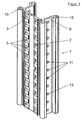
- FIG. 1 shows in perspective a rail-like longitudinal profile 1, which is part of a multi-part rail-like guide profile, suitable for the guidance of equipment, vehicles, transport devices, etc.
- a longitudinal rack or rack 5 in arranged a wall 3, having equally spaced holes 7.
- guide profile 1 is U-shaped, comprising two lateral leg surfaces 9, in which a longitudinal hole pattern 11 is arranged, comprising individual perforations 13. Finally provided are tubular guides 15, are guided on which guide rollers, holding glides or the like or attacking them.
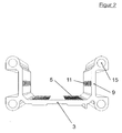
- FIG. 2 is in a perspective cross-section of the rail-like guide profile 1 from FIG. 1 shown, now the U-shaped cross-section is clearly visible.
- FIG. 3 shows profile elements 1 'and 1''are to be connected together so that the respective rasters 5' and 5 '' remain equally spaced at the transition from one to the other profile element.
- the transition of the screens should be uniform, so that the transition occurs, for example, a meshing in the grids gear from one to the other profile trouble-free.
- a connecting element 21 is provided, which is for example mirror-symmetrical to the two profiles also U-shaped.
- the connecting element 21 first as in Fig. 4 shown arranged in the U-shaped longitudinal groove of the profile 1 ", that the perforations of the two hole patterns are aligned exactly superimposed, thereby now connecting the connecting element 21 with the rail-like profile 1", for example by means of in FIG. 3 and 4 shown rivets 29 is possible.
- the introduction of such rivets 29 can for example be done by means of a so-called battery-driven rivet gun in the simplest manner.
- rivets for connecting the connecting element to the rail profiles may be advantageous, especially when high strength is required.
- the two parts to be joined such as the profile wall and the wall of the connecting element, are first guided against each other and finally pressed together.
- a screw connection eliminates the full and vepressende filling the perforations. This results in the use of rivets a higher strength and also adhere to the two parts to be joined much more closely to each other.
- increased strength in the area of joining two profiles can be an important factor.
- the further rail-like profile 1 ' can be guided over that connecting element 21, wherein arranged in the corners of the U-shaped profile longitudinal tubes 15' arranged on protruding pins 33 in the longitudinal tubes 15". the other rail-like profile 1 "can be performed to connect.
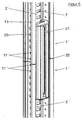
- FIG. 5 again shows in perspective the two rail-like profiles 1 'and 1''in the connected state, with the connecting element 21 arranged in the connection.
- the hole pattern of the connecting element 21 is in each case arranged congruently with the two hole patterns 11' and 11 ", wherein the Connection between the connecting element 21 and the two rail-like profiles 1 'and 1 "on the aforementioned rivet 29 is accomplished.
- such rail-like guide profiles can be used for guiding or driving transport devices, vehicles such as rail vehicles, climbing gear, etc.
- vehicles such as rail vehicles, climbing gear, etc.
- rail-like profiles for guiding Steilly and lifts on house walls, pylons, for guiding rescue equipment, etc.
- both the individual rail-like profiles and in particular the entire multi-part rail-like profile on a document such For example, a house wall, a high voltage pylons, a mast of a cable car, etc. can be stably arranged or mounted. This can be ensured for example by means of the above-mentioned inventive connecting element. Accordingly, for example, shows FIG.
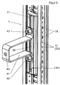
- FIG. 6 again in perspective a mounting or holding element 41, which is suitable for mounting or securing to a high voltage mast.
- This mounting member 41 may, for example via screw 43 at a corresponding centrally formed between each laterally projecting longitudinal edges 40 Montagelijnsnut 39 in the connecting element 21st be fastened or secured, which mounting member 41 in turn has a mounting portion 45, through which in turn by means of a screw the rail-like profile can be mounted or mounted on a base.
- connecting element Due to this dual function of the connecting element, this can also be arranged at any point of the rail-like guide profile to arrange the guide profile, for example, on a house facade or a high voltage pylons.
- connecting elements in addition to a mounting element can also be arranged along the rail-like guide profile, that is not in the region of the connection between two rail-like guide profiles in order to increase the mounting strength of the rail-like guide profiles in addition.
- FIGS. 1 to 6 is merely an example of the connection of two rail-like profile elements of a multi-part guide profile shown, which serves to further explain the present invention.
- the U-shaped rail-like profile shown is merely an example and, of course, the transmission of the present invention is also possible on a H-shaped, T-shaped, V-shaped or otherwise designed multi-part, rail-like, open or closed longitudinal profile.
- Even the choice of material is irrelevant in itself, so the profile of extruded stainless steel, aluminum or a other material such as a reinforced polymeric material.
- the rail-like guide profile is not limited to any application, but it can only serve as a rack designed as a drive mechanism for a vehicle or as a guide and drive rail for climbing equipment, for a lift, etc.
- any other arranged in the longitudinal direction of the profile divisions can be selected, in particular also codings, which are stored for example on longitudinally extending magnetic stripe.
- codes are formed, for example, analogous to the screening as evenly recurring pattern elements, which continue to be uniformly even in the transition from one to the next profile element or to be transmitted.
- the use of the connecting element proposed according to the invention makes sense.
- the proposed according to the invention multi-part rail-like profile is particularly suitable for climbing aids, or climbing equipment, as described in the international patent application W02005 / 016461 and the W02007 / 051341 ,
- a longitudinal grid or rack arrangement is formed as well as longitudinally extended pattern perforations, which are aligned with the grid or rack arrangement or agree with this.
- a connecting element for connecting two rail-like profiles which likewise has running in the longitudinal direction pattern elements which are in constant relation to the pattern perforations in the rail-like profile elements such as congruent.
Landscapes
- Engineering & Computer Science (AREA)
- Architecture (AREA)
- Mechanical Engineering (AREA)
- Civil Engineering (AREA)
- Structural Engineering (AREA)
- Connection Of Plates (AREA)
- Lift-Guide Devices, And Elevator Ropes And Cables (AREA)
- Sampling And Sample Adjustment (AREA)
- Gears, Cams (AREA)
- Transmission Devices (AREA)
- Automatic Analysis And Handling Materials Therefor (AREA)
Description
- Die vorliegende Erfindung betrifft ein mehrteiliges schienenartiges Profil gemäss dem Oberbegriff nach Anspruch 1 (siehe Z.B.
EP-A-1506799 ), die Verwendung des Profils sowie Verfahren zum Verbinden zweier Elemente eines mehrteiligen schienenartigen Profils. - Bei mehrteiligen schienenartigen Profilen, welche eine Längsrasterung oder eine Zahnstangeneinteilung aufweisen ist es jeweils ein Problem, dass im Übergang von einem Profilelement zum nächsten die Rasterung oder Zahnstangeneinteilung gleich beabstandet weitergeführt wird. Da in der Regel in der Rasterung bzw. der Zahnstangeneinteilung Geräte, Transportmittel oder Fahrzeuge geführt bzw. mittels der selben angetrieben werden, führt ein nicht genauer Übergang zu Bewegungsunterbrüchen, zu Ruckbewegungen oder gar dazu, dass das Fahrzeug oder Gerät aus der Rasterung oder der Zahnstangeneinteilung herausfällt.
- Sicher ist es möglich die einzelnen Profilelemente endständig je derart abzuschneiden, dass der Übergang korrekt ist, doch erfordert dies genauste Schneidetechnik und ein genaues zusammenfügen der einzelnen Profilelemente, was sehr aufwendig ist.
- Es ist daher eine Aufgabe der vorliegenden Erfindung eine Massnahme vorzuschlagen, mittels welcher eine Verbindung zweier schienenartigen Profilelemente einen genauen Übergang der Rasterung bzw. der Zahnstangeneinteilung gewährleistet bzw. dass die Rasterung bzw. Zahnstangeneinteilung gleich beabstandet vom einen zum nächsten Element geführt wird.
- Die gestellte Aufgabe wird erfindungsgemäss mittels einer Verbindung nach dem Wortlaut von Anspruch 1 gelöst.
- Vorgeschlagen wird, dass die Führungselemente bzw. Profile nebst der Rasterung oder Zahnstangeneinteilung in Längsrichtung des Profils verlaufende Musterlochungen aufweisen, welche einzelne Lochungen in gleich bleibender Relation zur Rasterung bzw. der Zahnstangeneinteilung angeordnet sind, vorzugsweise die Lochungen ausgerichtet auf die Rasterung oder Zahnstangeneinteilung. Zum Verbinden ist ein Verbindungselement vorgesehen, welches ebenfalls in Längsrichtung verlaufend entlang einer Längswandung weitere Musterlochungen aufweist, welche deckungsgleich zu den Musterlochungen in den Führungsprofilen sind.
- Das Verbindungselement wird mittels beispielsweise Niet- oder Schraubelementen mit je einem der beiden Profilelemente über die Lochmuster verbunden, wobei keine Lochung des Musters im Verbindungselement zwischen den beiden Profilenden unüberdeckt bleibt. Aufgrund der Kontinuität der Musterlochungen des Lochmusters von einem Profil zum nächsten über die Lochungen bzw. das Lochmuster im Verbindungselement wird sichergestellt, dass auch die Rasterung bzw. die Zahnstangeneinteilung distanzgleich bleibend von einem Profil zum nächsten übergeht. Nicht zur Erfindung gehörend sind statt Musterlochungen auch Nocken oder Erhebungen denkbar, welche beispielsweise federgespannt von der Längswandung nach aussen vorstehend angeordnet sind und im entsprechenden Lochmuster in der daran anliegenden Längswandung eingreifen um beispielsweise das Verbindungselement mit einem der Profilelemente fest zu verbinden. Anstelle von Lochungen können aber auch lediglich eingestanzte Vertiefungen vorgesehen sein, in welche die erwähnten Erhebungen oder Nocken zum Festlegen des Verbindungselementes am Profil eingreifen.
- Nicht zur Erfindung gehörend, kann anstelle einer Rasterung oder Zahnstangeneinteilung auch eine längs verlaufende Codierung vorgesehen sein, entlang welcher ein Gerät, ein Transportmittel oder dergleichen geführt bzw. angetrieben werden kann. Aber auch im Falle einer Codierung ist es wichtig, dass der Übergang von einem Profilelement zum nächsten gleichmässig resp. gleich bleibend erfolgt, was wiederum mittels der erwähnten Musterlochungen wie beispielsweise einem Lochmuster über das, zwischen den Profilen angeordnete Verbindungselement erfolgen kann.
- Das schienenartige Profil kann beispielsweise einen U-, H-, T-, V-, L- oder O-förmigen Querschnitt aufweisen bzw. einen offenen oder geschlossenen Querschnitt. In mindestens einer längsverlaufenden Wandung verläuft die Rasterung oder Zahnstangeneinteilung und in mindestens einer weiteren Längswandung die Musterlochungen wie das Lochmuster, welche zum Beispiel in Linie ausgerichtet zur Rasterung verlaufen bzw. je ein Loch des Musters, wie ein Loch genau neben je einer Öffnung bzw. einem Abschnitt der Rasterung oder Zahnstangeneinteilung zu liegen kommt. Entsprechend kann auch das Verbindungselement U-, H-, T-, V-, L- oder 0-förmig ausgebildet sein oder als zweidimensionale Längsschiene.
- Derartige schienenartige Profile können beispielsweise aus stranggepresstem Stahl oder Aluminium hergestellt sein oder aus einem anderen geeigneten Material wie einem verstärkten Polymer bestehen. So sind beispielsweise Aramid- oder kohlenstofffaserverstärkte Polymere wie Acetale, Polyamide, etc. bekannt welche äusserst formstabil sind, hohe Abriebfestigkeit aufweisen, schlagzäh sind, etc. und entsprechend als Ersatzmaterialien für Metalle geeignet sind. Weitere Polymerwerkstoffe werden laufend entwickelt um bei wesentlich geringerem Gewicht metallene Werkstoffe zu ersetzen.
- Die Materialwahl richtet sich nach der Verwendung der Schiene beispielsweise als Führung für ein Fahrzeug, ein Steiggerät, ein Lift, eine Rettungseinrichtung, eine Transporteinrichtung, etc.
- Die Erfindung wird nun beispielsweise und unter Bezug auf die beigefügten Figuren näher erläutert. Dabei zeigen:
-
Fig. 1 in Perspektive ein Element eines schienenartigen Profils, -
Fig. 2 das Element ausFigur 1 in Querschnittperspektive, -
Fig. 3 schematische Perspektive 2 zu verbindende schienenartige Profile sowie das zum Verbinden vorgesehene Verbindungselement, -
Fig. 4 ein Verbindungselement, eingesetzt in ein schienenartiges Profil wie dargestellt in denFiguren 1 und2 , -
Fig. 5 zwei schienenartige Profile zusammengefügt mittels eines erfindungsgemässen Verbindungselementes, und -
Fig. 6 die Verwendung des Verbindungselementes zum befestigen des schienenartigen Profils beispielsweise auf einer Unterlage an einer Gebäudewandung, an einem Hochspannungsmasten, etc. -
Figur 1 zeigt in Perspektive ein schienenartiges Längsprofil 1, welches Teil eines mehrteiligen schienenartigen Führungsprofils ist, geeignet für das Führen von Geräten, Fahrzeugen, Transporteinrichtungen, etc. Um derartige Geräte, Fahrzeuge oder Einrichtungen zu führen bzw. anzutreiben, ist eine Längsrasterung bzw. Zahnstangeneinteilung 5 in einer Wandung 3 angeordnet, aufweisend gleich beabstandete Lochungen 7. In diesen Lochungen 7 kann beispielsweise ein Zahnrad eingreifen, ein Stopmechanismus von Steiggeräten, etc. - Das in
Figur 1 gezeigte Führungsprofil 1 ist U-förmig ausgebildet, aufweisend zwei seitliche Schenkelflächen 9, in welchen ein längsverlaufendes Lochmuster 11 angeordnet ist, aufweisend einzelne Lochungen 13. Schliesslich vorgesehen sind rohrförmige Führungen 15, an welchen Führungsrollen, Haltegleiter oder dergleichen geführt sind oder an diesen angreifen. - In
Figur 2 ist in perspektivischem Querschnitt das schienenartige Führungsprofil 1 ausFigur 1 dargestellt, wobei nun der U-förmige Querschnitt deutlich erkennbar ist. - Um zwei schienenartige Führungsprofile derart zusammenzufügen, dass die Rasterung bzw. Zahnstangenenteilung 5 von einem Profil zum nächsten gleichbleibend beabstandet weitergeführt wird, wäre es an sich wichtig, dass endständig die beiden zusammenzufügenden Elemente genau abgeschnitten sind, damit an der Verbindungsfläche der Abstand zweier Rasterlochungen gleich ist wie je entlang der schienenartigen Profile. Dies ist aber in der Praxis kaum realisierbar oder aber nur mittels aufwendiger genauster Schneide- und Fügetechnik.
- Um eine genaue Verbindung herstellen zu können, wird nun erfindungsgemäss die Verwendung mind. eines Verbindungselementes vorgeschlagen, wie schematisch in Perspektive in
Figur 3 dargestellt. Die beiden inFigur 3 dargestellten Profilelemente 1' und 1'' sind derart miteinander zu verbinden, dass die jeweiligen Rasterungen 5' und 5'' beim Übergang vom einen zum anderen Profilelement gleich beabstandet bleiben. Mit anderen Worten soll der Übergang der Rasterungen gleichmässig sein, damit der Übergang beispielsweise eines in den Rasterungen eingreifenden Zahnrades von einem zum anderen Profil störungsfrei erfolgt. Zum Verbinden der beiden Profilelemente 1' und 1'' ist ein Verbindungselement 21 vorgesehen, welches beispielsweise spiegelsymmetrisch zu den beiden Profilen ebenfalls U-förmig ausgebildet ist. In den beiden Seitenschenkeln 23 des U-förmigen Verbindungselementes 21 ist ebenfalls je in Längsrichtung verlaufend ein Lochmuster 25 vorgesehen, aufweisend einzelne Lochungen 27. Dabei sind die einzelnen Lochungen 27 genau gleich, das heisst einen wenigstens nahezu gleichen Lochquerschnitt aufweisend, ausgebildet und beabstandet, wie die einzelnen Lochungen 13' und 13" des Lochmusters 11' und 11" in den Seitenschenkeln 9' und 9'' des jeweiligen schienenartigen Profiles 1' und 1'' . Entsprechend wird das Verbindungselement 21, zunächst wie inFig. 4 dargestellt derart in der U-förmigen Längsrinne des Profils 1" angeordnet, dass die Lochungen der beiden Lochmuster genau aufeinanderliegend ausgerichtet sind, wodurch nun ein Verbinden des Verbindungselementes 21 mit dem schienenartigen Profil 1" beispielsweise mittels den inFigur 3 und4 dargestellten Nieten 29 möglich wird. Das Einführen derartiger Nieten 29 kann beispielsweise mittel einer sogenannten akkugetriebenen Nietpistole auf einfachste Art und Weise erfolgen. - Die Verwendung von Nieten zum Verbinden des Verbindungselementes mit den Schienenprofilen kann vorteilhaft sein, insbesondere wenn hohe Festigkeit gefragt ist. Im Gegensatz zur Verwendung von Schraubverbindungen wird beim Festlegen einer Niete deren Querschnitt in der Lochung verbreitert bzw. die Niete wird im Lochungsquerschnitt verpresst. Dadurch wird beim Setzen einer Niete die Lochung vollständig ausgefüllt. Zusätzlich werden beim Setzen einer Niete die beiden zu verbindenden Teile wie die Profilwandung und die Wandung des Verbindungselementes zunächst aneinander geführt und schliesslich richtiggehend aneinander gepresst. Beim Verwenden einer Schraubverbindung entfällt das vollständige und vepressende Ausfüllen der Lochungen. Damit entsteht bei der Verwendung von Nieten eine höhere Festigkeit und zudem haften die beiden zu verbindenden Teile wesentlich stärker aneinander. Gerade bei den erfindungsgemäss beschriebenen schienenartigen Profilen kann eine erhöhte Festigkeit im Bereich des Verbindens zweier Profile ein wesentlicher Faktor sein.
- Je endständig am Verbindungselement 21 sind Überdeckungen und Abdeckkappen 32 bzw. 34 vorgesehen.
- Nach erfolgter Festlegung des Verbindungselementes 21 auf dem schienenartigen Profil 1" kann das weitere schienenartige Profil 1' über dass Verbindungselement 21 geführt werden, wobei die in den Ecken des U-förmigen Profils angeordneten Längsrohre 15' über vorstehende Stifte 33 angeordnet in den Längsrohren 15" des anderen schienenartigen Profils 1" zum verbinden geführt werden können.
-
Figur 5 zeigt wiederum in Perspektive die beiden schienenartigen Profile 1' und 1'' im verbundenen Zustand, mit dem in der Verbindung angeordneten Verbindungselement 21. Dabei ist das Lochmuster des Verbindungselementes 21 jeweils deckungsgleich mit den beiden Lochmustern 11' bzw. 11 " angeordnet, wobei die Verbindung zwischen Verbindungselement 21 und den beiden schienenartigen Profilen 1' und 1" über die bereits erwähnten Nietverbindungen 29 bewerkstelligt ist. - Aufgrund der Tatsache, dass die beiden Lochmuster 11' und 11" genau gleich beabstandet vom einen zum anderen schienenartigen Profil übertragen werden, ist nun auch gewährleitstet, dass die in der Stirnseite 3' bzw. 3" angeordnete Rasterung gleich beabstandet vom einen zum anderen Profil übertragen wird. Der zwischen den beiden schienenartigen Profilen entstehende Spalt 35 kann dabei bei den verschiedenen Übergängen unterschiedlich sein, die Rasterung bzw. Zahnstangeneinteilung jedoch wird immer gleichbleibend vom einen zum nächsten Profil übertragen.
- Wie bereits Eingangs erwähnt, können derartige schienenartige Führungsprofile für das Führen bzw. für den Antrieb von Transporteinrichtungen, Fahrzeugen wie Schienenfahrzeugen, Steiggeräten, etc. verwendet werden. Bekannt z.B. ist die Verwendung derartiger schienenartigen Profile für das Führen von Steiggeräten und Liften an Hauswänden, Hochspannungsmasten, für das Führen von Rettungsgeräten, etc. Dabei ist es wichtig, dass sowohl die einzelnen schienenartigen Profile wie insbesondere das gesamte mehrteilige schienenartige Profil auf einer Unterlagen wie beispielsweise einer Hauswand, einem Hochspannungsmasten, einem Masten einer Seilbahn, etc. stabil angeordnet bzw. montiert werden kann. Dies kann beispielsweise auch mittels des obenerwähnten erfindungsgemässen Verbindungselementes gewährleistet werden. Entsprechend zeigt beispielsweise
Figur 6 wiederum in Perspektive ein Montage- bzw. Halteelement 41, welches für die Montage bzw. das Sichern an einem Hochspannungsmast geeignet ist. Dieses Montagelement 41 kann beispielsweise über Schraubverbindungen 43 an einer entsprechenden mittig zwischen je seitlich vorstehenden Längsflanken 40 gebildeten Montagelängsnut 39 im Verbindungselement 21 befestigt bzw. gesichert werden, welches Montageelement 41 seinerseits einen Befestigungsbereich 45 aufweist, durch welchen hindurch wiederum mittels einer Schraubverbindung das schienenartige Profil auf einer Unterlage befestigt bzw. montiert werden kann. - Aufgrund dieser Doppelfunktion des Verbindungselementes kann dieses auch an irgendeiner Stelle des schienenartigen Führungsprofiles angeordnet werden, um das Führungsprofil beispielsweise an einer Hausfassade oder einem Hochspannungsmasten anzuordnen. Mit anderen Worten können Verbindungselemente zusätzlich aufweisend ein Montageelement auch entlang des schienenartigen Führungsprofils, das heisst nicht im Bereich der Verbindung zweier schienenartigen Führungsprofile angeordnet werden um die Montagefestigkeit der schienenartigen Führungsprofile zusätzlich zu erhöhen.
- In den
Figuren 1 bis 6 ist lediglich ein Beispiel der Verbindung zweier schienenartigen Profilelemente eines mehrteiligen Führungsprofils dargestellt, welches zur näheren Erläuterung der vorliegenden Erfindung dient. Insbesondere das gezeigte U-förmige schienenartige Profil ist lediglich ein Beispiel und selbstverständlich ist die Übertragung der vorliegenden Erfindung auch auf ein H-förmiges, T-förmiges, V-förmiges oder andersartig ausgebildetes mehrteiliges, schienenartiges, offenes oder geschlossenes Längsprofil möglich. Auch die Materialwahl ist an sich unerheblich, so kann das Profil aus stranggepresstem rostfreiem Stahl, Aluminium oder einem anderen Material bestehen wie beispielsweise einem verstärkten polymeren Material. - Entsprechend kann auch das Verbindungslement V-förmig, H-förmig, T-förmig, U-förmig, L-förmig, offen, geschlossen oder als zweidimensionale Längsplatte ausgebildet sein. Auch ist das schienenartige Führungsprofil nicht auf irgendeine Anwendung eingeschränkt, sondern es kann lediglich als Zahnstange ausgebildet als Antriebsmechanismus für ein Fahrzeug dienen oder aber als Führungs- und Antriebsschiene für Steiggeräte, für einen Lift, etc.
- Nicht zur Erfindung gehörend, können anstelle einer Rasterung oder Zahnstangeneinteilung auch irgendwelche andere in Längsrichtung des Profils vorgesehene Einteilungen gewählt werden, wie insbesondere auch Codierungen, welche beispielsweise auf sich längs erstreckenden Magnetstreifen abgespeichert sind. Diese Codierungen sind beispielsweise analog der Rasterung als gleichmässig periodisch wiederkehrende Musterelemente ausgebildet, welche auch beim Übergang vom einen zum nächsten Profilelement entsprechend gleichmässig fortzuführen bzw. zu übertragen sind. Auch in diesem Falle ist die Verwendung des erfindungsgemäss vorgeschlagenen Verbindungselementes sinnvoll.
- Nicht zur Erfindung gehörend, ist es auch möglich anstatt von Lochmustern gleichmässig beabstandet angeordnete Erhebungen, Nocken oder dergleichen zu verwenden, welche in entsprechenden Vertiefungen eingreifen. Dabei können diese Erhebungen oder Nocken entweder in den schienenartigen Profilelementen angeordnet sein und entsprechend die Vertiefungen bzw. Ausnehmungen im Verbindungselement oder umgekehrt. Diese Nocken können auch nach aussen vorstehend vorgespannt sein und so beispielsweise beim Einführen des Verbindungselementes in die Profile in die entsprechenden Ausnehmungen einschnappen bzw. einrasten.
- Das erfindungsgemäss vorgeschlagene mehrteilige schienenartige Profil ist insbesondere geeignet für Steighilfen, oder Steiggeräte, wie beschrieben in der internationalen Patentanmeldung
W02005/016461 und derW02007/051341 . - Wesentlich ist, dass im mehrteiligen Führungsprofil eine längs verlaufende Rasterung oder Zahnstangeneinteilung ausgebildet ist sowie längs ausgedehnte Musterlochungen, welche auf die Rasterung oder Zahnstangeneinteilung ausgerichtet sind bzw. mit dieser übereinstimmen. Weiter vorgesehen ist ein Verbindungselement zum Verbinden zweier schienenartiger Profile, welches ebenfalls in Längsrichtung verlaufend Musterelemente aufweist, welche in gleich bleibender Relation zu den Musterlochungen in den schienenartigen Profilelementen stehen wie beispielsweise deckungsgleich sind.
Claims (13)
- Mehrteiliges schienenartiges Profil bestehend aus mindestens zwei oder mehr zusammenfügbaren oder- steckbaren Profilelementen (1) mindestens aufweisend eine in Längsrichtung verlaufende Rasterung (5) oder Zahnstangeneinteilung, gekennzeichnet durch- Mindestens in einer Wandung jedes Profilelementes (1) verlaufende Musterlochungen (11) mit gleichmässig beabstandeten Lochungen (13) welche zu der Rasterung bzw. Zahnstangeneinteilung in gleichbleibender Relation angeordnet sind, und- ein Verbindungselement (21) mit einer weiteren Wandung (23), vorgesehen um an der Wandung des Profilelementes anzuliegen, mit längsverlaufenden, zu den Musterlochungen (11) deckungsgleichen weiteren Musterlochungen (25), deren Lochungen (27) übereinstimmend beabstandet sind.
- Profil nach Anspruch 1, dadurch gekennzeichnet, dass die Musterlochungen (11) sowie die weiteren Musterlochungen (25) Lochmuster sind.
- Profil nach Anspruch 1, dadurch gekennzeichnet, dass die Lochungen des Musters und die weiteren Lochungen wie die des weiteren Lochmusters gleich beabstandet sind wie die Abstände der Lochungen der Rasterung, der einzelnen Zähne der Zahnstangeneinteilung oder ein vielfaches davon, vorzugsweise ausgerichtet auf die Rasterung oder die Zahnstangeneinteilung.
- Profil nach einem der Ansprüche 2 oder 3, dadurch gekennzeichnet, dass Verbindungsorgane (29) vorgesehen sind, um die Lochungen des Lochmusters im Profil mit den Lochungen des weiteren Lochmusters im Verbindungselement zu verbinden.
- Profil nach Anspruch 4, dadurch gekennzeichnet, dass die Verbindungsorgane Nieten, Schrauben, Steckstifte, etc. sind.
- Profile nach einem der Ansprüche 1 bis 4, dadurch gekennzeichnet, dass die schienenartigen Profilelemente einen U-, H-, T-, V-, L-, O-förmig oder andersartig geeignet ausgebildeten Querschnitt aufweisen.
- Profil nach Anspruch 1 bis 6, dadurch gekennzeichnet, dass der Querschnitt des Verbindungselementes derart ist, dass ein Ein- bzw. Aufschieben auf die schienenartigen Profilelemente ermöglicht wird, so dass die Wandungen mit den Musterlochungen im Profil mit der weiteren Wandung mit den weiteren Musterlochungen aneinander bzw. aufeinander liegen mit Übereinstimmung der einzelnen Lochungen der Muster.
- Profil nach einem der Ansprüche 1 bis 7, dadurch gekennzeichnet, dass der Querschnitt der schienenartigen Profilelemente U-förmig ist und der Querschnitt des Verbindungselementes spiegelsymmetrisch U-förmig ist, derart, dass das Verbindungselement in die U-Rinne der Profilelemente spiegelsymmetrisch einschiebbar bzw. einfügbar ist.
- Profil nach einem der Ansprüche 1 bis 7, dadurch gekennzeichnet, dass sowohl die Profilelemente wie auch das Verbindungselement aus stranggepresstem Stahl oder Aluminium besteht, vorzugsweise alle Elemente aus dem selben Material gefertigt sind.
- Verwendung eines mehrteiligen schienenartigen Profils, nach einem der Ansprüche 1 bis 9, zum Führen bzw. Antreiben von Fahrzeugen, Steiggeräten, für einen Lift, für eine Rettungseinrichtung, eine Transporteinrichtung, etc.
- Profil nach einem der Ansprüche 1 bis 9, dadurch gekennzeichnet, dass das Verbindungselement (21) einen Montageabschnitt (39) aufweist, für das feste Anordnen des schienenartigen Profiles auf einer Unterlage wie an einer Hauswand, an einem Hochspannungsmasten, an einem Seilbahnmasten, etc.
- Profil nach Anspruch 11, dadurch gekennzeichnet, dass der Montageabschnitt durch eine Längsnut (39) gebildet wird, welche zwischen je seitlich vorstehenden und von Richtung der Unterlage hintergreifbaren Längsflanken (40) ausgebildet ist, wobei in der Längsnut, die Längsflanken hintergreifend mindestens ein Montagelement (41) fest positionierbar ist zum Festlegen des schienenartigen Profiles an bzw. auf einer Unterlage.
- Verfahren zum Verbinden mindestens zweier Profilelemente eines mehrteiligen schienenartigen Profils, dadurch gekennzeichnet, dass in den Profilelementen (1', 1'') des mehrteiligen Profils in Längsrichtung ausgebildet je Musterlochungen wie ein Lochmuster ausgebildet sind und dass zwischen zwei Profilelementen ein Verbindungselement eingeführt bzw. angelegt wird, welches ebenfalls in Längsrichtung ausgebildete weitere Musterlochungen wie ein weiteres Lochmuster aufweist, dessen einzelne Lochungen deckungsgleich sind bzw. gleich beabstandet sind wie die einzelnen Lochungen in den Mustern der Profilelemente und dass schliesslich mittels Nieten, Schraubverbindungen, Steckern, Spannstiften, etc. die beiden Profilelemente mit dem Verbindungselement verbunden werden, derart, dass zwischen den Profilelementen (1', 1") keine Lochungen im Verbindungselement unüberdeckt bleiben.
Priority Applications (1)
| Application Number | Priority Date | Filing Date | Title |
|---|---|---|---|
| PL08803676T PL2195488T3 (pl) | 2007-09-11 | 2008-09-04 | Połączenie szyn prowadzących |
Applications Claiming Priority (2)
| Application Number | Priority Date | Filing Date | Title |
|---|---|---|---|
| CH14182007 | 2007-09-11 | ||
| PCT/EP2008/061706 WO2009034010A2 (de) | 2007-09-11 | 2008-09-04 | Verbindung von führungsschienen |
Publications (2)
| Publication Number | Publication Date |
|---|---|
| EP2195488A2 EP2195488A2 (de) | 2010-06-16 |
| EP2195488B1 true EP2195488B1 (de) | 2013-02-27 |
Family
ID=40032842
Family Applications (1)
| Application Number | Title | Priority Date | Filing Date |
|---|---|---|---|
| EP08803676A Active EP2195488B1 (de) | 2007-09-11 | 2008-09-04 | Verbindung von führungsschienen |
Country Status (9)
| Country | Link |
|---|---|
| US (1) | US8033361B2 (de) |
| EP (1) | EP2195488B1 (de) |
| JP (1) | JP5781763B2 (de) |
| CN (1) | CN101802305B (de) |
| CA (1) | CA2698846C (de) |
| DK (1) | DK2195488T3 (de) |
| ES (1) | ES2408186T3 (de) |
| PL (1) | PL2195488T3 (de) |
| WO (1) | WO2009034010A2 (de) |
Cited By (1)
| Publication number | Priority date | Publication date | Assignee | Title |
|---|---|---|---|---|
| EP3434637A1 (de) | 2017-07-26 | 2019-01-30 | HighStep Systems AG | Plattformsystem |
Families Citing this family (24)
| Publication number | Priority date | Publication date | Assignee | Title |
|---|---|---|---|---|
| WO2009034010A2 (de) * | 2007-09-11 | 2009-03-19 | M+F Ingenieur Beratungs Ag | Verbindung von führungsschienen |
| FR2963380B1 (fr) * | 2010-06-01 | 2012-08-24 | Nergeco Sa | Porte rapide |
| CH704615A2 (de) | 2011-03-09 | 2012-09-14 | Highstep Systems Ag | Lift für Hochspannungs- und Windrad-Masten. |
| CN102303773B (zh) * | 2011-04-28 | 2016-03-16 | 奇瑞汽车股份有限公司 | 一种汽车焊装车间滑轨及其内部滑车安装方法 |
| CN102583134A (zh) * | 2012-03-03 | 2012-07-18 | 张家港市通达电梯装璜有限公司 | 一种电梯导轨连接块 |
| KR101248829B1 (ko) * | 2012-09-11 | 2013-04-02 | 한국지질자원연구원 | 해양퇴적물의 음파전달속도 측정용 샘플링 케이스 및 이 샘플링 케이스로 이루어지는 샘플링 장치 |
| CN103352401B (zh) * | 2013-07-24 | 2015-01-07 | 成都市新筑路桥机械股份有限公司 | 嵌入式轨道 |
| US9664337B2 (en) * | 2014-03-10 | 2017-05-30 | Combustion And Energy S.R.L. | Apparatus for transporting a device along a tower |
| WO2015183564A1 (en) * | 2014-05-29 | 2015-12-03 | Honeywell International Inc. | Guided type fall arrester - force control |
| TWI545277B (zh) * | 2014-06-17 | 2016-08-11 | Screw | |
| CN104909240A (zh) * | 2015-06-08 | 2015-09-16 | 北京国网富达科技发展有限责任公司 | 登塔装备使用的导轨 |
| EP3419924A1 (de) * | 2016-02-24 | 2019-01-02 | Otis Elevator Company | Aufzugsführungsschienenvernbinder mit veränderlichem querschnitt |
| CN105819304B (zh) * | 2016-05-25 | 2018-06-15 | 北京国网富达科技发展有限责任公司 | 一种在输电铁塔上使用的导轨单元和导轨 |
| CH712569A2 (de) | 2016-06-01 | 2017-12-15 | Highstep Systems Ag | Mobile Schiene und Anordnung mit mobilen Schienen. |
| CN106995016B (zh) * | 2017-02-22 | 2018-12-14 | 郑义恒 | 一种具有减速功能的拼接式防冻建筑物外墙攀爬轨道系统 |
| DE102017109839A1 (de) | 2017-05-08 | 2018-12-20 | Kewazo Gmbh | Gerüsttransportsystem, Verfahren zur Steuerung eines Gerüsttransportsystems sowie Verwendung eines Gerüsttransportsystems |
| CN107457514A (zh) * | 2017-06-20 | 2017-12-12 | 成都环龙智能机器人有限公司 | 一种焊接机器人工作台 |
| EP3421923A1 (de) * | 2017-06-28 | 2019-01-02 | OFTEC Handelsgesellschaft für Oberflächentechnik mbh | Führungsprofil |
| CN108910656B (zh) * | 2018-07-27 | 2019-05-21 | 煤炭工业合肥设计研究院有限责任公司 | 一种罐道连接装置及其连接方法 |
| IT201800008150A1 (it) * | 2018-08-22 | 2020-02-22 | Faresin Formwork Spa | Dispositivo di supporto e guida di una trave di cassaforma rampicante e tale trave |
| FR3098210B1 (fr) * | 2019-07-01 | 2022-01-28 | Sodimas | Installation d’ascenseur comprenant un guide en aluminium |
| CN112320241B (zh) * | 2020-11-18 | 2025-07-01 | 龚忠华 | 一种多功能跑道 |
| CN112411873A (zh) * | 2020-11-27 | 2021-02-26 | 湖南鸿阳钢结构有限公司 | 一种扩展型h型钢梁 |
| KR102825769B1 (ko) * | 2024-10-21 | 2025-06-26 | 주식회사 더이로운 | 맨홀에 설치되는 추락방지장치 |
Family Cites Families (24)
| Publication number | Priority date | Publication date | Assignee | Title |
|---|---|---|---|---|
| US341639A (en) * | 1886-05-11 | Elevator | ||
| DE1012320B (de) | 1955-09-19 | 1957-07-18 | Gutehoffnungshuette Sterkrade | Unterteilte Triebstockbahn |
| JPS5124747Y2 (de) * | 1971-04-30 | 1976-06-24 | ||
| US3884153A (en) * | 1971-12-23 | 1975-05-20 | Minoru Sugimoto | Monorail structure |
| US3968858A (en) * | 1975-05-14 | 1976-07-13 | Vollan Douglas D | Climbing device |
| US4499966A (en) * | 1983-02-22 | 1985-02-19 | Tundra Holdings Ltd. | Emergency escape system |
| DK277184A (da) | 1983-06-06 | 1984-12-07 | Extralumin Metallurg Ind | Arbejdsstillads i form af en bjaelke eller soejle med en klatremekanisme |
| US4629032A (en) * | 1983-09-21 | 1986-12-16 | Armstrong James A | Building wall descent device having a manually operated brake means |
| AU567801B2 (en) | 1984-04-05 | 1987-12-03 | Fox Manufacturing Co. Pty. Ltd. | Entry section for a rack and pinion railway. |
| US4828072A (en) * | 1986-11-14 | 1989-05-09 | Ho I Chung | High rise building fire escape/fire fighting and building maintenance system |
| US4887694A (en) * | 1986-11-14 | 1989-12-19 | Ho I Chung | High rise building fire escape/fire fighting and building maintenance system |
| US4709782A (en) * | 1987-01-13 | 1987-12-01 | Henry Lipinski | Skid-out highrise fire escape device |
| SE469718B (sv) * | 1987-01-23 | 1993-08-30 | Wamag Idab Ab | Transportoerskena foer styrning av en kedja |
| JPH10139305A (ja) * | 1996-11-08 | 1998-05-26 | Yoshikawa:Kk | 家庭用エレベーターのガイドレール |
| JPH10297842A (ja) * | 1997-04-22 | 1998-11-10 | Otis Elevator Co | エレベーターのガイドレール用目板 |
| JPH11116161A (ja) * | 1997-10-20 | 1999-04-27 | Tobu Sankyo Kk | ガイドレール |
| US6161647A (en) * | 1999-01-25 | 2000-12-19 | Pitt-Des Moines, Inc. | Fall arresting ladder safety device |
| JP4533479B2 (ja) * | 1999-10-21 | 2010-09-01 | オーチス エレベータ カンパニー | エレベータの案内装置 |
| CA2303619C (en) * | 2000-03-31 | 2009-12-08 | Martin Faucher | Support structures |
| DE10319175A1 (de) | 2003-04-29 | 2005-01-27 | Strohm, Regina, geb. Wetzel | Sicherungsvorrichtung zur Verwendung an turmartigen Bauwerken |
| DE10337121B3 (de) * | 2003-08-11 | 2005-06-09 | Manfred Josef Wallner | Kranbahnschiene |
| EP1506799A1 (de) * | 2003-08-14 | 2005-02-16 | M+F Ingenieur Beratungs AG | Steighilfe |
| CH715330B1 (de) | 2005-11-07 | 2020-03-13 | Highstep Systems Ag | Anordnung zum Auf- und/oder Absteigen einer Person. |
| WO2009034010A2 (de) * | 2007-09-11 | 2009-03-19 | M+F Ingenieur Beratungs Ag | Verbindung von führungsschienen |
-
2008
- 2008-09-04 WO PCT/EP2008/061706 patent/WO2009034010A2/de not_active Ceased
- 2008-09-04 PL PL08803676T patent/PL2195488T3/pl unknown
- 2008-09-04 JP JP2010524463A patent/JP5781763B2/ja active Active
- 2008-09-04 US US12/677,645 patent/US8033361B2/en active Active
- 2008-09-04 ES ES08803676T patent/ES2408186T3/es active Active
- 2008-09-04 DK DK08803676.9T patent/DK2195488T3/da active
- 2008-09-04 CN CN2008801066136A patent/CN101802305B/zh active Active
- 2008-09-04 EP EP08803676A patent/EP2195488B1/de active Active
- 2008-09-04 CA CA2698846A patent/CA2698846C/en active Active
Cited By (1)
| Publication number | Priority date | Publication date | Assignee | Title |
|---|---|---|---|---|
| EP3434637A1 (de) | 2017-07-26 | 2019-01-30 | HighStep Systems AG | Plattformsystem |
Also Published As
| Publication number | Publication date |
|---|---|
| US8033361B2 (en) | 2011-10-11 |
| US20100252645A1 (en) | 2010-10-07 |
| CN101802305B (zh) | 2013-07-17 |
| ES2408186T3 (es) | 2013-06-18 |
| CA2698846A1 (en) | 2009-03-19 |
| DK2195488T3 (da) | 2013-05-27 |
| WO2009034010A3 (de) | 2009-04-30 |
| EP2195488A2 (de) | 2010-06-16 |
| CA2698846C (en) | 2016-02-09 |
| JP2010538937A (ja) | 2010-12-16 |
| WO2009034010A2 (de) | 2009-03-19 |
| CN101802305A (zh) | 2010-08-11 |
| PL2195488T3 (pl) | 2013-08-30 |
| JP5781763B2 (ja) | 2015-09-24 |
Similar Documents
| Publication | Publication Date | Title |
|---|---|---|
| WO2009034010A2 (de) | Verbindung von führungsschienen | |
| DE2815296B2 (de) | Vorrichtung zum Befestigen ausgerichteter Rahmen in einer Wandöffnung | |
| EP2610412B1 (de) | Fugenanker für eine Trennfuge zwischen Betonwandelementen | |
| EP0045019B1 (de) | Zerlegbare Leiter, insbesondere Schachtleiter | |
| EP2355275A2 (de) | Befestigungsvorrichtung und Einschubprofil | |
| DE3638048C2 (de) | ||
| DE69717010T2 (de) | Senkrecht bewegbare Scheibe eines Kraftfahrzeugfensters | |
| DE3136597A1 (de) | Rollenbahn | |
| CH712569A2 (de) | Mobile Schiene und Anordnung mit mobilen Schienen. | |
| DE2937121A1 (de) | Schiebedachantrieb | |
| DE2313050C2 (de) | Vorrichtung zur Verbindung des Gewindekabels eines Kabelfensterhebers mit einer verschiebbaren Fensterscheibe, insbesondere an Kraftfahrzeugen | |
| EP2101019A2 (de) | Riegelstangenanordnung für ein Fenster oder eine Tür, Fenster oder Tür mit wenigstens einer Riegelstangenanordnung, Schaltschrank mit einem Fenster oder einer Tür sowie ein Verfahren zum Befestigen einer Riegelstangenanordnung an einem Fenster oder einer Tür | |
| DE4110185C1 (de) | ||
| DE2810630C3 (de) | Verbundprofil | |
| WO2019110348A1 (de) | Verbindungsanordnung | |
| DE2158948C3 (de) | Eckbeschlag für Fenster und Türen od. dgl., insbesondere Eckumlenkung für Treibstangenbeschläge | |
| DE4434589C2 (de) | Verfahren zur Herstellung von Formschlußelementen für eine Vorrichtung zum Verbinden einer Fensterscheibe mit einem Fensterheber | |
| EP0291973B1 (de) | Verbindungsstück für zwei winklig aneinanderstossende Profilstäbe von Fenster oder Türrahmen | |
| DE202012101263U1 (de) | Gehrungsverbindung | |
| DE2232804C3 (de) | Verbindung für ein Rahmenprofil | |
| EP1873340A2 (de) | Türanlage | |
| DE202013105425U1 (de) | Abstandshalter für eine Gleitführung und Hubsäule | |
| EP3653826B1 (de) | Befestigungsmittel für die befestigung von rahmen für fenster, türen, pforten oder fassaden, verfahren und anordnung | |
| DE2462536C3 (de) | Verbindung eines Sprossenprofils mit einem Rahmenprofil eines Fensterrahmens, Türrahmens o.dgl. | |
| DE202004014821U1 (de) | Linearführungseinheit mit außenliegender Führung einer Anschlussplatte |
Legal Events
| Date | Code | Title | Description |
|---|---|---|---|
| PUAI | Public reference made under article 153(3) epc to a published international application that has entered the european phase |
Free format text: ORIGINAL CODE: 0009012 |
|
| 17P | Request for examination filed |
Effective date: 20100330 |
|
| AK | Designated contracting states |
Kind code of ref document: A2 Designated state(s): AT BE BG CH CY CZ DE DK EE ES FI FR GB GR HR HU IE IS IT LI LT LU LV MC MT NL NO PL PT RO SE SI SK TR |
|
| AX | Request for extension of the european patent |
Extension state: AL BA MK RS |
|
| DAX | Request for extension of the european patent (deleted) | ||
| GRAP | Despatch of communication of intention to grant a patent |
Free format text: ORIGINAL CODE: EPIDOSNIGR1 |
|
| GRAS | Grant fee paid |
Free format text: ORIGINAL CODE: EPIDOSNIGR3 |
|
| GRAA | (expected) grant |
Free format text: ORIGINAL CODE: 0009210 |
|
| AK | Designated contracting states |
Kind code of ref document: B1 Designated state(s): AT BE BG CH CY CZ DE DK EE ES FI FR GB GR HR HU IE IS IT LI LT LU LV MC MT NL NO PL PT RO SE SI SK TR |
|
| REG | Reference to a national code |
Ref country code: GB Ref legal event code: FG4D Free format text: NOT ENGLISH |
|
| REG | Reference to a national code |
Ref country code: CH Ref legal event code: EP |
|
| REG | Reference to a national code |
Ref country code: AT Ref legal event code: REF Ref document number: 598616 Country of ref document: AT Kind code of ref document: T Effective date: 20130315 |
|
| REG | Reference to a national code |
Ref country code: IE Ref legal event code: FG4D Free format text: LANGUAGE OF EP DOCUMENT: GERMAN |
|
| REG | Reference to a national code |
Ref country code: DE Ref legal event code: R096 Ref document number: 502008009365 Country of ref document: DE Effective date: 20130425 |
|
| REG | Reference to a national code |
Ref country code: RO Ref legal event code: EPE |
|
| REG | Reference to a national code |
Ref country code: DK Ref legal event code: T3 |
|
| REG | Reference to a national code |
Ref country code: CH Ref legal event code: NV Representative=s name: TROESCH SCHEIDEGGER WERNER AG, CH |
|
| REG | Reference to a national code |
Ref country code: SE Ref legal event code: TRGR |
|
| REG | Reference to a national code |
Ref country code: ES Ref legal event code: FG2A Ref document number: 2408186 Country of ref document: ES Kind code of ref document: T3 Effective date: 20130618 |
|
| REG | Reference to a national code |
Ref country code: NL Ref legal event code: T3 |
|
| REG | Reference to a national code |
Ref country code: LT Ref legal event code: MG4D |
|
| PG25 | Lapsed in a contracting state [announced via postgrant information from national office to epo] |
Ref country code: IS Free format text: LAPSE BECAUSE OF FAILURE TO SUBMIT A TRANSLATION OF THE DESCRIPTION OR TO PAY THE FEE WITHIN THE PRESCRIBED TIME-LIMIT Effective date: 20130627 Ref country code: BG Free format text: LAPSE BECAUSE OF FAILURE TO SUBMIT A TRANSLATION OF THE DESCRIPTION OR TO PAY THE FEE WITHIN THE PRESCRIBED TIME-LIMIT Effective date: 20130527 Ref country code: LT Free format text: LAPSE BECAUSE OF FAILURE TO SUBMIT A TRANSLATION OF THE DESCRIPTION OR TO PAY THE FEE WITHIN THE PRESCRIBED TIME-LIMIT Effective date: 20130227 Ref country code: NO Free format text: LAPSE BECAUSE OF FAILURE TO SUBMIT A TRANSLATION OF THE DESCRIPTION OR TO PAY THE FEE WITHIN THE PRESCRIBED TIME-LIMIT Effective date: 20130527 |
|
| PG25 | Lapsed in a contracting state [announced via postgrant information from national office to epo] |
Ref country code: SI Free format text: LAPSE BECAUSE OF FAILURE TO SUBMIT A TRANSLATION OF THE DESCRIPTION OR TO PAY THE FEE WITHIN THE PRESCRIBED TIME-LIMIT Effective date: 20130227 Ref country code: FI Free format text: LAPSE BECAUSE OF FAILURE TO SUBMIT A TRANSLATION OF THE DESCRIPTION OR TO PAY THE FEE WITHIN THE PRESCRIBED TIME-LIMIT Effective date: 20130227 Ref country code: GR Free format text: LAPSE BECAUSE OF FAILURE TO SUBMIT A TRANSLATION OF THE DESCRIPTION OR TO PAY THE FEE WITHIN THE PRESCRIBED TIME-LIMIT Effective date: 20130528 Ref country code: PT Free format text: LAPSE BECAUSE OF FAILURE TO SUBMIT A TRANSLATION OF THE DESCRIPTION OR TO PAY THE FEE WITHIN THE PRESCRIBED TIME-LIMIT Effective date: 20130627 Ref country code: LV Free format text: LAPSE BECAUSE OF FAILURE TO SUBMIT A TRANSLATION OF THE DESCRIPTION OR TO PAY THE FEE WITHIN THE PRESCRIBED TIME-LIMIT Effective date: 20130227 |
|
| REG | Reference to a national code |
Ref country code: PL Ref legal event code: T3 |
|
| PG25 | Lapsed in a contracting state [announced via postgrant information from national office to epo] |
Ref country code: HR Free format text: LAPSE BECAUSE OF FAILURE TO SUBMIT A TRANSLATION OF THE DESCRIPTION OR TO PAY THE FEE WITHIN THE PRESCRIBED TIME-LIMIT Effective date: 20130227 |
|
| PG25 | Lapsed in a contracting state [announced via postgrant information from national office to epo] |
Ref country code: EE Free format text: LAPSE BECAUSE OF FAILURE TO SUBMIT A TRANSLATION OF THE DESCRIPTION OR TO PAY THE FEE WITHIN THE PRESCRIBED TIME-LIMIT Effective date: 20130227 Ref country code: SK Free format text: LAPSE BECAUSE OF FAILURE TO SUBMIT A TRANSLATION OF THE DESCRIPTION OR TO PAY THE FEE WITHIN THE PRESCRIBED TIME-LIMIT Effective date: 20130227 |
|
| PG25 | Lapsed in a contracting state [announced via postgrant information from national office to epo] |
Ref country code: CY Free format text: LAPSE BECAUSE OF FAILURE TO SUBMIT A TRANSLATION OF THE DESCRIPTION OR TO PAY THE FEE WITHIN THE PRESCRIBED TIME-LIMIT Effective date: 20130227 |
|
| PLBE | No opposition filed within time limit |
Free format text: ORIGINAL CODE: 0009261 |
|
| STAA | Information on the status of an ep patent application or granted ep patent |
Free format text: STATUS: NO OPPOSITION FILED WITHIN TIME LIMIT |
|
| 26N | No opposition filed |
Effective date: 20131128 |
|
| REG | Reference to a national code |
Ref country code: DE Ref legal event code: R097 Ref document number: 502008009365 Country of ref document: DE Effective date: 20131128 |
|
| BERE | Be: lapsed |
Owner name: HIGHSTEP SYSTEMS A.G. Effective date: 20130930 |
|
| PG25 | Lapsed in a contracting state [announced via postgrant information from national office to epo] |
Ref country code: MC Free format text: LAPSE BECAUSE OF FAILURE TO SUBMIT A TRANSLATION OF THE DESCRIPTION OR TO PAY THE FEE WITHIN THE PRESCRIBED TIME-LIMIT Effective date: 20130227 |
|
| REG | Reference to a national code |
Ref country code: IE Ref legal event code: MM4A |
|
| PG25 | Lapsed in a contracting state [announced via postgrant information from national office to epo] |
Ref country code: IE Free format text: LAPSE BECAUSE OF NON-PAYMENT OF DUE FEES Effective date: 20130904 Ref country code: BE Free format text: LAPSE BECAUSE OF NON-PAYMENT OF DUE FEES Effective date: 20130930 |
|
| PG25 | Lapsed in a contracting state [announced via postgrant information from national office to epo] |
Ref country code: MT Free format text: LAPSE BECAUSE OF FAILURE TO SUBMIT A TRANSLATION OF THE DESCRIPTION OR TO PAY THE FEE WITHIN THE PRESCRIBED TIME-LIMIT Effective date: 20130227 |
|
| PG25 | Lapsed in a contracting state [announced via postgrant information from national office to epo] |
Ref country code: LU Free format text: LAPSE BECAUSE OF NON-PAYMENT OF DUE FEES Effective date: 20130904 Ref country code: HU Free format text: LAPSE BECAUSE OF FAILURE TO SUBMIT A TRANSLATION OF THE DESCRIPTION OR TO PAY THE FEE WITHIN THE PRESCRIBED TIME-LIMIT; INVALID AB INITIO Effective date: 20080904 |
|
| REG | Reference to a national code |
Ref country code: FR Ref legal event code: PLFP Year of fee payment: 9 |
|
| PGFP | Annual fee paid to national office [announced via postgrant information from national office to epo] |
Ref country code: RO Payment date: 20160902 Year of fee payment: 9 |
|
| REG | Reference to a national code |
Ref country code: FR Ref legal event code: PLFP Year of fee payment: 10 |
|
| PGFP | Annual fee paid to national office [announced via postgrant information from national office to epo] |
Ref country code: TR Payment date: 20170815 Year of fee payment: 10 |
|
| PG25 | Lapsed in a contracting state [announced via postgrant information from national office to epo] |
Ref country code: RO Free format text: LAPSE BECAUSE OF NON-PAYMENT OF DUE FEES Effective date: 20170904 |
|
| REG | Reference to a national code |
Ref country code: FR Ref legal event code: PLFP Year of fee payment: 11 |
|
| PG25 | Lapsed in a contracting state [announced via postgrant information from national office to epo] |
Ref country code: CZ Free format text: LAPSE BECAUSE OF NON-PAYMENT OF DUE FEES Effective date: 20180904 |
|
| PG25 | Lapsed in a contracting state [announced via postgrant information from national office to epo] |
Ref country code: TR Free format text: LAPSE BECAUSE OF NON-PAYMENT OF DUE FEES Effective date: 20180904 |
|
| P01 | Opt-out of the competence of the unified patent court (upc) registered |
Effective date: 20230514 |
|
| PGFP | Annual fee paid to national office [announced via postgrant information from national office to epo] |
Ref country code: NL Payment date: 20250826 Year of fee payment: 18 |
|
| REG | Reference to a national code |
Ref country code: CH Ref legal event code: U11 Free format text: ST27 STATUS EVENT CODE: U-0-0-U10-U11 (AS PROVIDED BY THE NATIONAL OFFICE) Effective date: 20251001 |
|
| PGFP | Annual fee paid to national office [announced via postgrant information from national office to epo] |
Ref country code: DK Payment date: 20250911 Year of fee payment: 18 Ref country code: DE Payment date: 20250819 Year of fee payment: 18 |
|
| PGFP | Annual fee paid to national office [announced via postgrant information from national office to epo] |
Ref country code: PL Payment date: 20250826 Year of fee payment: 18 Ref country code: IT Payment date: 20250827 Year of fee payment: 18 |
|
| PGFP | Annual fee paid to national office [announced via postgrant information from national office to epo] |
Ref country code: GB Payment date: 20250814 Year of fee payment: 18 |
|
| PGFP | Annual fee paid to national office [announced via postgrant information from national office to epo] |
Ref country code: FR Payment date: 20250821 Year of fee payment: 18 Ref country code: AT Payment date: 20250827 Year of fee payment: 18 |
|
| PGFP | Annual fee paid to national office [announced via postgrant information from national office to epo] |
Ref country code: SE Payment date: 20250827 Year of fee payment: 18 |
|
| PGFP | Annual fee paid to national office [announced via postgrant information from national office to epo] |
Ref country code: CH Payment date: 20251001 Year of fee payment: 18 |
|
| PGFP | Annual fee paid to national office [announced via postgrant information from national office to epo] |
Ref country code: ES Payment date: 20251015 Year of fee payment: 18 |