EP2196272B1 - Gusskörper und Verfahren zur Herstellung eines Gusskörpers - Google Patents
Gusskörper und Verfahren zur Herstellung eines Gusskörpers Download PDFInfo
- Publication number
- EP2196272B1 EP2196272B1 EP08105928A EP08105928A EP2196272B1 EP 2196272 B1 EP2196272 B1 EP 2196272B1 EP 08105928 A EP08105928 A EP 08105928A EP 08105928 A EP08105928 A EP 08105928A EP 2196272 B1 EP2196272 B1 EP 2196272B1
- Authority
- EP
- European Patent Office
- Prior art keywords
- code
- cast body
- casting
- cast
- code carrier
- Prior art date
- Legal status (The legal status is an assumption and is not a legal conclusion. Google has not performed a legal analysis and makes no representation as to the accuracy of the status listed.)
- Active
Links
Images


Classifications
-
- B—PERFORMING OPERATIONS; TRANSPORTING
- B22—CASTING; POWDER METALLURGY
- B22C—FOUNDRY MOULDING
- B22C23/00—Tools; Devices not mentioned before for moulding
-
- B—PERFORMING OPERATIONS; TRANSPORTING
- B22—CASTING; POWDER METALLURGY
- B22D—CASTING OF METALS; CASTING OF OTHER SUBSTANCES BY THE SAME PROCESSES OR DEVICES
- B22D17/00—Pressure die casting or injection die casting, i.e. casting in which the metal is forced into a mould under high pressure
- B22D17/20—Accessories: Details
- B22D17/22—Dies; Die plates; Die supports; Cooling equipment for dies; Accessories for loosening and ejecting castings from dies
- B22D17/2245—Dies; Die plates; Die supports; Cooling equipment for dies; Accessories for loosening and ejecting castings from dies having walls provided with means for marking or patterning
-
- B—PERFORMING OPERATIONS; TRANSPORTING
- B22—CASTING; POWDER METALLURGY
- B22D—CASTING OF METALS; CASTING OF OTHER SUBSTANCES BY THE SAME PROCESSES OR DEVICES
- B22D19/00—Casting in, on, or around objects which form part of the product
Definitions
- the invention relates to a cast body, on which a machine-readable code containing information associated with the cast body is arranged, and a method for producing such a cast body.
- the traceability of production data individually assigned to each casting, for example, is important for process optimization, quality assurance and damage limitation in the delivery of non-conforming products.
- the important in this respect production data are z.
- a minimum requirement today for the marking of castings is usually that the model number and the time of the casting are noted on the casting.
- references to the heat treatment that has been carried out in each case are frequently also required, if such has been used.
- casting punches In order to apply this information to the respective cast body, so-called "casting punches" are used in practice. These contain information about the year, the calendar week and the shift in which the cast body concerned has been poured. For this purpose, the casting dies are inserted into the respective casting mold in such a way that the corresponding markings provided on their end face are impressed into the cast body during casting.
- the object of the invention to provide a way to uniquely identify castings, which is also suitable for such modern casting processes in which no suitable for the placement of a sign or the like opening is available.
- a method for producing such a cast body should be specified.
- the invention is based on the idea of prefabricating a code carrier and then pouring this code carrier into the respective cast body in such a way that the code existing on it can be read easily and assigned to the process data of the respective process step for the purpose of documentation.
- the code is carried by a separately prefabricated code carrier as in the prior art.
- this code carrier is cast with at least one section into the feeder or another element of the cast body to be separated from the cast green body after casting and thus permanently connected to the cast body.
- the code carried by the code carrier is preferably a machine-readable code, as known per se in many embodiments. Codings of this type are applied to the code carrier, for example in the form of letters and other strings, points, strokes or hatching. They can be reliably detected by an optical scanning system and allow, for example, the storage of a large amount of information in the form of redundant data, which still allow a clear identification of the respective cast body, if the coding of the code carrier is partially unreadable.
- the optically readable code on the code carrier, for example by means of a suitable inkjet printer.
- a particularly robust, the conditions prevailing in rough casting conditions conditions coding of the code carrier is obtained, however, if the code is engraved in the code carrier, for example by laser engraving.
- the laser engraving allows an exact picture of the respective code, which can then be read with high recognition reliability by an automatically operating detection device, such as a reader equipped with a commercial CMOS camera or a line scanner.
- the code carried by the code carrier may be a Data Matrix Code (DMC).
- DMC Data Matrix Code
- ISO International Organization for Standardization
- coding can be carried by a code carrier provided according to the invention.
- a code carrier provided according to the invention.
- the code carrier can carry an RFID chip (Radio Frequency Identification), which can be read out without contact with radio waves.
- the inventively provided separate prefabrication of the code carrier allows to provide the code carrier already outside the mold with the machine-readable code. It must neither respect one by the casting-related production conditional arrangement of the code are taken on the casting, nor is the nature of the representation of the code limited by the fact that the code must be imprinted in the form of an impression in the cast body. Instead, the code carrier remains with the code carried by him after solidification and removal from the casting.
- a corresponding area can be provided on the code carrier, for example by laser or other suitable means the respective code will be left.
- the marking according to the invention of a cast body by means of a separately prefabricated code carrier thus makes it possible in a particularly simple manner to provide a cast body with individual information which enables its unambiguous identification without any problems, in particular by means of an automatically operating detection system.
- the arrangement of the machine-readable code on a separately manufactured and then in the course of casting connected to the casting body code carrier allows to use codes that include a comprehensive information content. This can go far beyond the information that can be presented with the comparably simple means of identification, which in the state of Technique commonly used for marking of castings.
- This identifier can, for example, be a number from a consecutive number range.
- the casting bodies each provided with a code carrier in a data processing device can be assigned the process data that are essential for the respective cast body in such a way that they can be found again easily and unambiguously at a later point in time.
- the essential advantage of the invention over the prior art is then that the existing code on the code code can be easily designed and arranged so that it can be automatically detected with high reliability and processed for data processing further processing.
- the code carrier Since the code carrier is firmly connected to the cast body by pouring, it is also ensured that the information on the code carrier, the respective cast body clearly individualizing information also is not lost under the rough conditions prevailing in the casting plant.
- the code carrier is arranged in the region of the feeder or another required for the casting of the cast body, after solidification of the Gussrohteil separated element element.
- This proves to be particularly useful in a variant of the inventive method in which the code carried by the code code is read after solidification and removal of the cast body by means of a code detection device in which the information contained in the code is stored in a data processing device in which the Information stored in the data processing device is associated with an individual identification, and in which finally the identification is permanently impressed permanently into the cast body.
- the code containing the respective information on the cast body is first read out and then replaced by a unique individualizing the respective cast body, which is molded captive into the cast body as embossing or as a comparable form element.
- This identifier may be, for example, a simple alphanumeric string or the like, by which the respective cast body is numbered consecutively.
- the separation of the code carrier can also be targeted in the variant of the method according to the invention described above.
- the code carrier when molded into a feeder or other molding required to cast the casting, can be severed with the molding concerned after the code detecting device has read the code carried by the code carrier.
- it can also be useful to separate at least the portion of the code carrier carrying the code from the cast body in order to then have it read out by the detection device. This may be expedient, for example, if the read signals of the detection device were disturbed as a result of the geometry of the respective cast body.
- the code carried by the code carrier code individualized the respective cast body only in the sense of a unique identifier without even contain the information essential for tracing the manufacturing process
- the assignment of the relevant information to the respective cast body can be done by the code carried by the code carrier is read after the solidification and demolding of the cast body by means of a code detection device that the code stored in a data processing device, the Information associated with the manufacturing process of the code carrier cast body information that the data stored in the data processing device, the read code associated with an individual identification is assigned and that the relevant label is embossed into the cast body.
- the code of the code carrier is used solely to identify the respective cast body, links this identification with process data already stored in a data processing device and then produces a marking which will finally be left on the cast body in such a way that it is later Time ensures a clear assignment of the casting to its process data.
- the advantage of this approach according to the invention consists in the fact that the identification of the cast body required for data acquisition is not effected by means of a casting technique produced on the cast body and difficult to detect automatically due to the poor precision of its image, but a code can be used as the marking optimally adapted to the requirements of machine readability.
- the code carrier is selectively separated from the cast body at a certain point in the production process, then it is expedient to produce the code carrier from a material belonging to the same material class as the cast material of the cast body. In this way, the code carrier and the firmly bonded to the code carrier, separated from the cast body molding together melted and cast to a new cast body.
- the code holder may also be expedient to manufacture the code holder from a different material than the cast body.
- it may be favorable, for example, under certain process conditions, if the code holder has a particular temperature resistance or dimensional stability which could not be achieved by using a material belonging to the class of the respective cast material of the cast body for its production.
- the coding can be arranged on a section of the code carrier which is freely visible on the finished cast part.
- the code carrier may comprise a code bearing portion and an identification portion projecting from the identification portion, which is cast in the cast body.
- the identification section can easily project from the attachment section such that the identification section protrudes freely from the finished cast body in the manner of a flag.
- the code carrier can already be arranged in the casting mold, a fastening section of the code carrier is arranged in a mold cavity of the casting mold which images the cast body. By filling the mold with melt then the code carrier is firmly connected to the cast body. Accordingly, a variant of the invention provides that the code carrier is attached to a molded part, in particular a casting core, of the casting mold in which the cast body is cast in such a way that its section to be cast into the cast body is arranged in the flow path of the melt.
- a position of the code carrier which is as precisely as possible with respect to the cast body can also be ensured by first coupling the code carrier in a form-fitting manner to the casting mold.
- the code carrier can also be glued to the casting mold, as long as it is ensured that the code carrier can be released from the casting mold after casting and solidification of the cast body without damaging the code. This is ensured, for example, if at least a portion of the casting mold is formed by a sand core and the code carrier is fixed with a core adhesive on the sand core.
- the cast body according to the invention is poured in a lost mold, which is destroyed during removal of the cast body, it may also be appropriate to embed the code carrying portion of the code carrier completely in the respective mold part of the mold, so that the code before is protected from contact with the melt.
- this may for example happen that the marking portion of the code carrier shot into the sand core, that is sheathed in the production of the sand core with molding material.
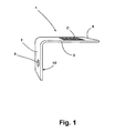
- Fig. 1 prefabricated in a separate step code carrier 1 is used to mark each cast one of an aluminum melt
- a cast body M which is in the present case is a crankcase for an internal combustion engine.
- the cast body M can also be a cylinder head for an internal combustion engine or another casting, in its nature and Properties are placed particularly high demands.
- the code carrier 1 is folded from a sheet metal strip, which consists of an aluminum material of the class, which also belongs to the molten aluminum of the respective engine block M.
- the code carrier 1 can be made of pure aluminum.
- the code carrier 1 has a fastening section 2 and a marking section 3 projecting at right angles therefrom. In the attachment portion 2, an opening 4 is formed.
- a larger number of code carriers 2, each carrying an individual code C, are provided at a station, not shown here, at which a lost mold, also not shown here, is assembled as a core package of different mold parts and casting cores.
- the casting moldings and the casting cores may consist of a molding material mixed with molding sand and binder.
- the invention can also be used regardless of whether it is in the mold parts or casting cores to lost, destroyed in the removal of the respective casting elements is.
- the casting mold is a permanent casting mold (mold) used for many casting operations. If necessary, lost, made of molding material casting cores can be used in such a permanent mold.
- cover core 6 Of the casting cores and moldings of the casting mold, only one cover core 6 is shown here in section ( Figures 2,3 ).
- the cover core 6 has a flat upper side 7.
- a Feiserausnaturalung 8 is formed, via which during the casting of the not visible here, the cast body M imaging the interior of the mold with aluminum melt A is fed.
- a code carrier 1 is fastened in each case with its fastening section 2 to one of the walls 9, which delimit the feeder recess 8 and are aligned substantially at right angles to the flat upper side 7 of the cover core 6.
- the attachment portion 2 is glued with its the labeling portion 3 of the code carrier 1 associated side surface 10 flat to the relevant wall 9, so that the labeling portion 3 at a distance above the top 7 of the cover core 6 and of the Feiserausströmung 8 is pointing away. In this way, it is ensured that the marking section 3 is not hit by melt spatter during casting of the aluminum melt A in the mold.
- a production data record PD is then created in a data processing system DV, in which the essential process parameters of the subsequently completed production steps are stored. These process parameters may be the exact timing of the casting, the casting speed, the melt temperature, the type of production equipment, the type of heat treatment, etc. Also, the passing between the laying of the cover core 6 and the casting time can be detected and stored in the process data set PD.
- the relevant production data set PD is uniquely associated with the respective casting M to be poured in the correspondingly prepared casting mold.
- the cohesive connection of the code carrier 1 to the cover core 6 has the advantage that even when the mold is turned after its filling with the melt, as is customary in modern Rotationsg intelligentmaschine, the code carrier 1 securely retains its position.
- the aluminum melt A rises in the FeiserausEnglishung 8 until a certain desired height of the melt level is reached.
- the molten aluminum A flows around the attachment section 2 of the code carrier 1 and penetrates into its opening 4.
- the code carrier 1 is firmly and in a captive manner poured into the surrounding aluminum casting material which has penetrated into its opening 4 and from which the feeder S formed in the feeder recess 8 is made.
- the identification section 3 is accordingly free from the feeder S of the cast body M.
- the code C is arranged on its freely visible upper side so that it can be easily read by an optical code detection device 11.
- the cast body M is conveyed to this code detection device 11 after it has left the demoulding station (not shown here).
- the code detection station 11 reads out the respective code C of the casting body M reaching it, for example, notes the time of detection in the process data record PD assigned to it in the data processing installation DV so that the process data record PD is considered complete, and then sends the one Cast body M also clearly individualizing code C 'to a laser engraving device 12, to which the cast body M passes in the next process step.
- the laser engraving device 12 imprinted by means of a laser beam the code C 'in a designated surface of the cast body M.
- the code C' may be identical to the code carrier 1 carried code C match or it may be in the code C 'readable as a plain text string act.
- the engraving made by the laser engraving device 12 is such that the code C 'can be unambiguously recognized even after a long service life of the internal combustion engine built using the cast body M.
- the feeder S After impressing the code C 'in the cast body M, the feeder S is separated with the code carrier 1 of the cast body M and melted again to aluminum melt.
- existing coding C ' is at any time traceable, which production record PD is associated with the relevant cast body M. Accordingly, in case of damage or quality defects can be easily determined when and under what conditions the respective cast body M has been made.
- the code C 'embossed into the cast body M is available for process-reliable, automatic identification. This ensures that all other process parameters essential for the quality of the cast body M can also be assigned to the process data record PD.
- An inventive code carrier 1 thus makes it possible to make an exact marking of the cast body M, without the need for an agent, such as a casting die or the like, must already be provided in the mold, which the information contained in it on the respective cast body M only inaccurate maps.
Landscapes
- Engineering & Computer Science (AREA)
- Mechanical Engineering (AREA)
- Casting Devices For Molds (AREA)
- Pinball Game Machines (AREA)
- General Factory Administration (AREA)
- Mold Materials And Core Materials (AREA)
Priority Applications (4)
| Application Number | Priority Date | Filing Date | Title |
|---|---|---|---|
| AT08105928T ATE554869T1 (de) | 2008-12-03 | 2008-12-03 | Gusskörper und verfahren zur herstellung eines gusskörpers |
| EP08105928A EP2196272B1 (de) | 2008-12-03 | 2008-12-03 | Gusskörper und Verfahren zur Herstellung eines Gusskörpers |
| ES08105928T ES2389817T3 (es) | 2008-12-03 | 2008-12-03 | Cuerpo de fundición y procedimiento para la fabricación de un cuerpo de fundición |
| PL08105928T PL2196272T3 (pl) | 2008-12-03 | 2008-12-03 | Odlew i sposób wytwarzania odlewu |
Applications Claiming Priority (1)
| Application Number | Priority Date | Filing Date | Title |
|---|---|---|---|
| EP08105928A EP2196272B1 (de) | 2008-12-03 | 2008-12-03 | Gusskörper und Verfahren zur Herstellung eines Gusskörpers |
Publications (2)
| Publication Number | Publication Date |
|---|---|
| EP2196272A1 EP2196272A1 (de) | 2010-06-16 |
| EP2196272B1 true EP2196272B1 (de) | 2012-04-25 |
Family
ID=40627662
Family Applications (1)
| Application Number | Title | Priority Date | Filing Date |
|---|---|---|---|
| EP08105928A Active EP2196272B1 (de) | 2008-12-03 | 2008-12-03 | Gusskörper und Verfahren zur Herstellung eines Gusskörpers |
Country Status (4)
| Country | Link |
|---|---|
| EP (1) | EP2196272B1 (pl) |
| AT (1) | ATE554869T1 (pl) |
| ES (1) | ES2389817T3 (pl) |
| PL (1) | PL2196272T3 (pl) |
Cited By (1)
| Publication number | Priority date | Publication date | Assignee | Title |
|---|---|---|---|---|
| DE102015102308A1 (de) | 2015-02-18 | 2016-08-18 | Nemak, S.A.B. De C.V. | Verfahren zum Kennzeichnen eines Gussteils |
Families Citing this family (3)
| Publication number | Priority date | Publication date | Assignee | Title |
|---|---|---|---|---|
| DE102015203797A1 (de) * | 2015-03-03 | 2016-09-08 | Fraunhofer-Gesellschaft zur Förderung der angewandten Forschung e.V. | Gusskörper, Verfahren zu seiner Herstellung sowie Gießwerkzeug zur Herstellung des Gusskörpers |
| DE102019202750B3 (de) * | 2019-02-28 | 2020-03-12 | Fraunhofer-Gesellschaft zur Förderung der angewandten Forschung e.V. | Verfahren zur Kennzeichnung von Metallgussbauteilen mittels elektronischer Transponder |
| EP3736064A1 (en) * | 2019-05-10 | 2020-11-11 | Disa Industries A/S | Foundry production line and method of operating such foundry production line |
Family Cites Families (2)
| Publication number | Priority date | Publication date | Assignee | Title |
|---|---|---|---|---|
| US4900637A (en) | 1988-10-07 | 1990-02-13 | Aluminum Company Of America | Tag for labeling an article cast from molten material, method therefore and article |
| JPH0475761A (ja) | 1990-03-30 | 1992-03-10 | Toto Ltd | 情報マークを有する鋳物製品 |
-
2008
- 2008-12-03 PL PL08105928T patent/PL2196272T3/pl unknown
- 2008-12-03 ES ES08105928T patent/ES2389817T3/es active Active
- 2008-12-03 AT AT08105928T patent/ATE554869T1/de active
- 2008-12-03 EP EP08105928A patent/EP2196272B1/de active Active
Cited By (3)
| Publication number | Priority date | Publication date | Assignee | Title |
|---|---|---|---|---|
| DE102015102308A1 (de) | 2015-02-18 | 2016-08-18 | Nemak, S.A.B. De C.V. | Verfahren zum Kennzeichnen eines Gussteils |
| WO2016132196A1 (de) | 2015-02-18 | 2016-08-25 | Nemak, S.A.B. De C.V. | Verfahren zum kennzeichnen eines gussteils |
| US10052686B2 (en) | 2015-02-18 | 2018-08-21 | Nemak, S.A.B. De C.V. | Method for identifying a cast part |
Also Published As
| Publication number | Publication date |
|---|---|
| ATE554869T1 (de) | 2012-05-15 |
| PL2196272T3 (pl) | 2012-11-30 |
| ES2389817T3 (es) | 2012-11-02 |
| EP2196272A1 (de) | 2010-06-16 |
Similar Documents
| Publication | Publication Date | Title |
|---|---|---|
| EP3283246B1 (de) | Verfahren zum kennzeichnen eines gussteils | |
| DE202008018295U1 (de) | Gusskörper | |
| EP2196272B1 (de) | Gusskörper und Verfahren zur Herstellung eines Gusskörpers | |
| DE19713861A1 (de) | Verfahren und Vorrichtung zum Identifizieren von Formgußteilen und zum Verfolgen von Formgießprozeß-Parametern | |
| EP0564861A1 (de) | Verfahren und Vorrichtung zur individuellen Kennzeichnung von Nassguss-Sandformen | |
| DE102004028218A1 (de) | Verfahren zur Herstellung eines tragbaren Datenträgers | |
| DE10225668A1 (de) | Gießen von Motorblöcken | |
| EP1981667B1 (de) | VERFAHREN ZUM MONTIEREN EINER GIEßFORM ZUM GIEßEN EINES GUSSTEILS AUS EINER METALLSCHMELZE | |
| DE68903728T2 (de) | Verfahren zum etikettieren eines giesskoerpers, etikett dazu und giesskoerper. | |
| EP0832706A3 (de) | Druckgiessmaschine | |
| DE19925674B4 (de) | Kennzeichnung von Gußteilen | |
| DE102019202750B3 (de) | Verfahren zur Kennzeichnung von Metallgussbauteilen mittels elektronischer Transponder | |
| DE69705577T2 (de) | Giessvorrichtung und -verfahren für optische Platten | |
| DE602004004828T2 (de) | Kennzeichnungsmethode und -system für Stahlabschnitte | |
| DE602005000892T2 (de) | Verfahren zur Entfernung des Gipses einer Pressform für Fiesen und Zusatzgeräte oder dergleichen und Einheit zur Durchführung dieses Verfahrens | |
| EP3603847A2 (de) | Einzelteilrückverfolgung von feingussbauteilen und das bereitstellen von maschinenlesbaren codes auf feingussbauteilen | |
| AT519404B1 (de) | Verfahren zur Sicherung eines RFID-Chips sowie Stempelplatte | |
| EP2386367B1 (de) | Verfahren zur entformung in sandgiessform erstarrter gussteile | |
| DE102019213180B4 (de) | Verfahren und Herstellungseinrichtung zum Herstellen eines Gussteils | |
| CN108290207B (zh) | 型芯的造型方法 | |
| EP2452764A1 (de) | Speiserkappe mit integrierter Transportvorrichtung | |
| EP1686668B2 (de) | Verfahren zur Herstellung von Elektroinstallationsmaterial | |
| DE102019207991A1 (de) | Markierungsverfahren und Markierungsvorrichtung für ein Gussteil | |
| DE102015203802A1 (de) | Formkörper mit einem Datenspeicher | |
| DD287881A5 (de) | Verfahren zur uebermittlung technologischer angaben |
Legal Events
| Date | Code | Title | Description |
|---|---|---|---|
| PUAI | Public reference made under article 153(3) epc to a published international application that has entered the european phase |
Free format text: ORIGINAL CODE: 0009012 |
|
| 17P | Request for examination filed |
Effective date: 20100319 |
|
| AK | Designated contracting states |
Kind code of ref document: A1 Designated state(s): AT BE BG CH CY CZ DE DK EE ES FI FR GB GR HR HU IE IS IT LI LT LU LV MC MT NL NO PL PT RO SE SI SK TR |
|
| AX | Request for extension of the european patent |
Extension state: AL BA MK RS |
|
| AKX | Designation fees paid |
Designated state(s): AT BE BG CH CY CZ DE DK EE ES FI FR GB GR HR HU IE IS IT LI LT LU LV MC MT NL NO PL PT RO SE SI SK TR |
|
| GRAP | Despatch of communication of intention to grant a patent |
Free format text: ORIGINAL CODE: EPIDOSNIGR1 |
|
| RTI1 | Title (correction) |
Free format text: CASTING PIECE AND METHOD FOR MANUFACTURING A CASTING PIECE |
|
| RIN1 | Information on inventor provided before grant (corrected) |
Inventor name: AICHBERGER, THOMAS |
|
| GRAS | Grant fee paid |
Free format text: ORIGINAL CODE: EPIDOSNIGR3 |
|
| GRAA | (expected) grant |
Free format text: ORIGINAL CODE: 0009210 |
|
| AK | Designated contracting states |
Kind code of ref document: B1 Designated state(s): AT BE BG CH CY CZ DE DK EE ES FI FR GB GR HR HU IE IS IT LI LT LU LV MC MT NL NO PL PT RO SE SI SK TR |
|
| REG | Reference to a national code |
Ref country code: GB Ref legal event code: FG4D Free format text: NOT ENGLISH |
|
| REG | Reference to a national code |
Ref country code: CH Ref legal event code: EP |
|
| REG | Reference to a national code |
Ref country code: AT Ref legal event code: REF Ref document number: 554869 Country of ref document: AT Kind code of ref document: T Effective date: 20120515 |
|
| REG | Reference to a national code |
Ref country code: IE Ref legal event code: FG4D Free format text: LANGUAGE OF EP DOCUMENT: GERMAN |
|
| REG | Reference to a national code |
Ref country code: DE Ref legal event code: R096 Ref document number: 502008007049 Country of ref document: DE Effective date: 20120628 |
|
| REG | Reference to a national code |
Ref country code: RO Ref legal event code: EPE |
|
| REG | Reference to a national code |
Ref country code: NL Ref legal event code: VDEP Effective date: 20120425 |
|
| LTIE | Lt: invalidation of european patent or patent extension |
Effective date: 20120425 |
|
| PG25 | Lapsed in a contracting state [announced via postgrant information from national office to epo] |
Ref country code: CY Free format text: LAPSE BECAUSE OF FAILURE TO SUBMIT A TRANSLATION OF THE DESCRIPTION OR TO PAY THE FEE WITHIN THE PRESCRIBED TIME-LIMIT Effective date: 20120425 Ref country code: SE Free format text: LAPSE BECAUSE OF FAILURE TO SUBMIT A TRANSLATION OF THE DESCRIPTION OR TO PAY THE FEE WITHIN THE PRESCRIBED TIME-LIMIT Effective date: 20120425 Ref country code: IS Free format text: LAPSE BECAUSE OF FAILURE TO SUBMIT A TRANSLATION OF THE DESCRIPTION OR TO PAY THE FEE WITHIN THE PRESCRIBED TIME-LIMIT Effective date: 20120825 Ref country code: NO Free format text: LAPSE BECAUSE OF FAILURE TO SUBMIT A TRANSLATION OF THE DESCRIPTION OR TO PAY THE FEE WITHIN THE PRESCRIBED TIME-LIMIT Effective date: 20120725 Ref country code: LT Free format text: LAPSE BECAUSE OF FAILURE TO SUBMIT A TRANSLATION OF THE DESCRIPTION OR TO PAY THE FEE WITHIN THE PRESCRIBED TIME-LIMIT Effective date: 20120425 Ref country code: FI Free format text: LAPSE BECAUSE OF FAILURE TO SUBMIT A TRANSLATION OF THE DESCRIPTION OR TO PAY THE FEE WITHIN THE PRESCRIBED TIME-LIMIT Effective date: 20120425 |
|
| REG | Reference to a national code |
Ref country code: ES Ref legal event code: FG2A Ref document number: 2389817 Country of ref document: ES Kind code of ref document: T3 Effective date: 20121102 |
|
| PG25 | Lapsed in a contracting state [announced via postgrant information from national office to epo] |
Ref country code: LV Free format text: LAPSE BECAUSE OF FAILURE TO SUBMIT A TRANSLATION OF THE DESCRIPTION OR TO PAY THE FEE WITHIN THE PRESCRIBED TIME-LIMIT Effective date: 20120425 Ref country code: HR Free format text: LAPSE BECAUSE OF FAILURE TO SUBMIT A TRANSLATION OF THE DESCRIPTION OR TO PAY THE FEE WITHIN THE PRESCRIBED TIME-LIMIT Effective date: 20120425 Ref country code: GR Free format text: LAPSE BECAUSE OF FAILURE TO SUBMIT A TRANSLATION OF THE DESCRIPTION OR TO PAY THE FEE WITHIN THE PRESCRIBED TIME-LIMIT Effective date: 20120726 Ref country code: PT Free format text: LAPSE BECAUSE OF FAILURE TO SUBMIT A TRANSLATION OF THE DESCRIPTION OR TO PAY THE FEE WITHIN THE PRESCRIBED TIME-LIMIT Effective date: 20120827 Ref country code: SI Free format text: LAPSE BECAUSE OF FAILURE TO SUBMIT A TRANSLATION OF THE DESCRIPTION OR TO PAY THE FEE WITHIN THE PRESCRIBED TIME-LIMIT Effective date: 20120425 |
|
| REG | Reference to a national code |
Ref country code: PL Ref legal event code: T3 |
|
| REG | Reference to a national code |
Ref country code: SK Ref legal event code: T3 Ref document number: E 12561 Country of ref document: SK |
|
| PG25 | Lapsed in a contracting state [announced via postgrant information from national office to epo] |
Ref country code: EE Free format text: LAPSE BECAUSE OF FAILURE TO SUBMIT A TRANSLATION OF THE DESCRIPTION OR TO PAY THE FEE WITHIN THE PRESCRIBED TIME-LIMIT Effective date: 20120425 Ref country code: DK Free format text: LAPSE BECAUSE OF FAILURE TO SUBMIT A TRANSLATION OF THE DESCRIPTION OR TO PAY THE FEE WITHIN THE PRESCRIBED TIME-LIMIT Effective date: 20120425 Ref country code: NL Free format text: LAPSE BECAUSE OF FAILURE TO SUBMIT A TRANSLATION OF THE DESCRIPTION OR TO PAY THE FEE WITHIN THE PRESCRIBED TIME-LIMIT Effective date: 20120425 |
|
| REG | Reference to a national code |
Ref country code: HU Ref legal event code: AG4A Ref document number: E015055 Country of ref document: HU |
|
| PLBE | No opposition filed within time limit |
Free format text: ORIGINAL CODE: 0009261 |
|
| STAA | Information on the status of an ep patent application or granted ep patent |
Free format text: STATUS: NO OPPOSITION FILED WITHIN TIME LIMIT |
|
| 26N | No opposition filed |
Effective date: 20130128 |
|
| REG | Reference to a national code |
Ref country code: DE Ref legal event code: R097 Ref document number: 502008007049 Country of ref document: DE Effective date: 20130128 |
|
| BERE | Be: lapsed |
Owner name: NEMAK LINZ GMBH Effective date: 20121231 |
|
| PG25 | Lapsed in a contracting state [announced via postgrant information from national office to epo] |
Ref country code: MC Free format text: LAPSE BECAUSE OF NON-PAYMENT OF DUE FEES Effective date: 20121231 |
|
| REG | Reference to a national code |
Ref country code: CH Ref legal event code: PL |
|
| GBPC | Gb: european patent ceased through non-payment of renewal fee |
Effective date: 20121203 |
|
| REG | Reference to a national code |
Ref country code: IE Ref legal event code: MM4A |
|
| PG25 | Lapsed in a contracting state [announced via postgrant information from national office to epo] |
Ref country code: BE Free format text: LAPSE BECAUSE OF NON-PAYMENT OF DUE FEES Effective date: 20121231 |
|
| PG25 | Lapsed in a contracting state [announced via postgrant information from national office to epo] |
Ref country code: CH Free format text: LAPSE BECAUSE OF NON-PAYMENT OF DUE FEES Effective date: 20121231 Ref country code: IE Free format text: LAPSE BECAUSE OF NON-PAYMENT OF DUE FEES Effective date: 20121203 Ref country code: LI Free format text: LAPSE BECAUSE OF NON-PAYMENT OF DUE FEES Effective date: 20121231 |
|
| PG25 | Lapsed in a contracting state [announced via postgrant information from national office to epo] |
Ref country code: GB Free format text: LAPSE BECAUSE OF NON-PAYMENT OF DUE FEES Effective date: 20121203 Ref country code: MT Free format text: LAPSE BECAUSE OF FAILURE TO SUBMIT A TRANSLATION OF THE DESCRIPTION OR TO PAY THE FEE WITHIN THE PRESCRIBED TIME-LIMIT Effective date: 20120425 |
|
| PG25 | Lapsed in a contracting state [announced via postgrant information from national office to epo] |
Ref country code: LU Free format text: LAPSE BECAUSE OF NON-PAYMENT OF DUE FEES Effective date: 20121203 |
|
| PGFP | Annual fee paid to national office [announced via postgrant information from national office to epo] |
Ref country code: BG Payment date: 20141204 Year of fee payment: 7 Ref country code: CZ Payment date: 20141112 Year of fee payment: 7 Ref country code: SK Payment date: 20141112 Year of fee payment: 7 Ref country code: RO Payment date: 20141119 Year of fee payment: 7 |
|
| PGFP | Annual fee paid to national office [announced via postgrant information from national office to epo] |
Ref country code: HU Payment date: 20141215 Year of fee payment: 7 |
|
| REG | Reference to a national code |
Ref country code: FR Ref legal event code: PLFP Year of fee payment: 8 |
|
| PG25 | Lapsed in a contracting state [announced via postgrant information from national office to epo] |
Ref country code: CZ Free format text: LAPSE BECAUSE OF NON-PAYMENT OF DUE FEES Effective date: 20151203 |
|
| REG | Reference to a national code |
Ref country code: SK Ref legal event code: MM4A Ref document number: E 12561 Country of ref document: SK Effective date: 20151203 |
|
| PG25 | Lapsed in a contracting state [announced via postgrant information from national office to epo] |
Ref country code: HU Free format text: LAPSE BECAUSE OF NON-PAYMENT OF DUE FEES Effective date: 20151204 Ref country code: BG Free format text: LAPSE BECAUSE OF NON-PAYMENT OF DUE FEES Effective date: 20160930 |
|
| PG25 | Lapsed in a contracting state [announced via postgrant information from national office to epo] |
Ref country code: SK Free format text: LAPSE BECAUSE OF NON-PAYMENT OF DUE FEES Effective date: 20151203 |
|
| REG | Reference to a national code |
Ref country code: FR Ref legal event code: PLFP Year of fee payment: 9 |
|
| PG25 | Lapsed in a contracting state [announced via postgrant information from national office to epo] |
Ref country code: RO Free format text: LAPSE BECAUSE OF NON-PAYMENT OF DUE FEES Effective date: 20151203 |
|
| REG | Reference to a national code |
Ref country code: FR Ref legal event code: PLFP Year of fee payment: 10 |
|
| PGFP | Annual fee paid to national office [announced via postgrant information from national office to epo] |
Ref country code: AT Payment date: 20251215 Year of fee payment: 18 |
|
| PGFP | Annual fee paid to national office [announced via postgrant information from national office to epo] |
Ref country code: FR Payment date: 20251217 Year of fee payment: 18 |
|
| PGFP | Annual fee paid to national office [announced via postgrant information from national office to epo] |
Ref country code: TR Payment date: 20251128 Year of fee payment: 18 |
|
| PGFP | Annual fee paid to national office [announced via postgrant information from national office to epo] |
Ref country code: PL Payment date: 20251121 Year of fee payment: 18 |
|
| PGFP | Annual fee paid to national office [announced via postgrant information from national office to epo] |
Ref country code: ES Payment date: 20260119 Year of fee payment: 18 |
|
| PGFP | Annual fee paid to national office [announced via postgrant information from national office to epo] |
Ref country code: DE Payment date: 20251222 Year of fee payment: 18 |
|
| PGFP | Annual fee paid to national office [announced via postgrant information from national office to epo] |
Ref country code: IT Payment date: 20251231 Year of fee payment: 18 |