EP3283246B1 - Verfahren zum kennzeichnen eines gussteils - Google Patents
Verfahren zum kennzeichnen eines gussteils Download PDFInfo
- Publication number
- EP3283246B1 EP3283246B1 EP16704474.2A EP16704474A EP3283246B1 EP 3283246 B1 EP3283246 B1 EP 3283246B1 EP 16704474 A EP16704474 A EP 16704474A EP 3283246 B1 EP3283246 B1 EP 3283246B1
- Authority
- EP
- European Patent Office
- Prior art keywords
- casting
- information
- identification element
- license plate
- mold
- Prior art date
- Legal status (The legal status is an assumption and is not a legal conclusion. Google has not performed a legal analysis and makes no representation as to the accuracy of the status listed.)
- Active
Links
Images




Classifications
-
- B—PERFORMING OPERATIONS; TRANSPORTING
- B22—CASTING; POWDER METALLURGY
- B22D—CASTING OF METALS; CASTING OF OTHER SUBSTANCES BY THE SAME PROCESSES OR DEVICES
- B22D17/00—Pressure die casting or injection die casting, i.e. casting in which the metal is forced into a mould under high pressure
- B22D17/20—Accessories: Details
- B22D17/22—Dies; Die plates; Die supports; Cooling equipment for dies; Accessories for loosening and ejecting castings from dies
- B22D17/2245—Dies; Die plates; Die supports; Cooling equipment for dies; Accessories for loosening and ejecting castings from dies having walls provided with means for marking or patterning
-
- B—PERFORMING OPERATIONS; TRANSPORTING
- B22—CASTING; POWDER METALLURGY
- B22D—CASTING OF METALS; CASTING OF OTHER SUBSTANCES BY THE SAME PROCESSES OR DEVICES
- B22D19/00—Casting in, on, or around objects which form part of the product
- B22D19/04—Casting in, on, or around objects which form part of the product for joining parts
-
- B—PERFORMING OPERATIONS; TRANSPORTING
- B22—CASTING; POWDER METALLURGY
- B22C—FOUNDRY MOULDING
- B22C23/00—Tools; Devices not mentioned before for moulding
-
- B—PERFORMING OPERATIONS; TRANSPORTING
- B22—CASTING; POWDER METALLURGY
- B22C—FOUNDRY MOULDING
- B22C9/00—Moulds or cores; Moulding processes
- B22C9/10—Cores; Manufacture or installation of cores
-
- B—PERFORMING OPERATIONS; TRANSPORTING
- B22—CASTING; POWDER METALLURGY
- B22D—CASTING OF METALS; CASTING OF OTHER SUBSTANCES BY THE SAME PROCESSES OR DEVICES
- B22D19/00—Casting in, on, or around objects which form part of the product
-
- B—PERFORMING OPERATIONS; TRANSPORTING
- B22—CASTING; POWDER METALLURGY
- B22D—CASTING OF METALS; CASTING OF OTHER SUBSTANCES BY THE SAME PROCESSES OR DEVICES
- B22D31/00—Cutting-off surplus material, e.g. gates; Cleaning and working on castings
-
- B—PERFORMING OPERATIONS; TRANSPORTING
- B22—CASTING; POWDER METALLURGY
- B22D—CASTING OF METALS; CASTING OF OTHER SUBSTANCES BY THE SAME PROCESSES OR DEVICES
- B22D45/00—Equipment for casting, not otherwise provided for
-
- B—PERFORMING OPERATIONS; TRANSPORTING
- B22—CASTING; POWDER METALLURGY
- B22D—CASTING OF METALS; CASTING OF OTHER SUBSTANCES BY THE SAME PROCESSES OR DEVICES
- B22D46/00—Controlling, supervising, not restricted to casting covered by a single main group, e.g. for safety reasons
-
- B—PERFORMING OPERATIONS; TRANSPORTING
- B29—WORKING OF PLASTICS; WORKING OF SUBSTANCES IN A PLASTIC STATE IN GENERAL
- B29C—SHAPING OR JOINING OF PLASTICS; SHAPING OF MATERIAL IN A PLASTIC STATE, NOT OTHERWISE PROVIDED FOR; AFTER-TREATMENT OF THE SHAPED PRODUCTS, e.g. REPAIRING
- B29C45/00—Injection moulding, i.e. forcing the required volume of moulding material through a nozzle into a closed mould; Apparatus therefor
- B29C45/17—Component parts, details or accessories; Auxiliary operations
- B29C45/26—Moulds
- B29C45/37—Mould cavity walls, i.e. the inner surface forming the mould cavity, e.g. linings
Definitions
- the invention relates to a method for producing a casting provided with readable information.
- castings produced according to the invention components which are generally produced by casting technology are counted here in the completely solidified and demolded. Castings of the inventively produced type are therefore freed from the required for their casting production moldings such as feeders, gates, inlets, seams and the like, as they are usually removed after solidification by a termed in the jargon also as "cleaning" post.
- the castings produced according to the invention are components for the production of internal combustion engines.
- the castings produced according to the invention therefore include cylinder heads and crankcases intended especially for internal combustion engines.
- important production data are, for example, the production time, casting speed, casting temperatures, type of production plant, etc.
- a possibility known from the state of the art to attach the information required for a clear individualization of the respective casting to the casting with the required depth is to use a casting core inserted in a casting mold for molding cavities, channels or the outer contour of the casting by means of a laser to provide a negative image of a unique string, which is imaged in the course of the casting process on the casting and there is visible after casting.
- Information shown on the casting can be used in the casting process with an automatically operating device, such as in the JP 04 075761 is described.
- the object was to provide a method which allows the production of castings that are permanently, especially in the ready state, provided with readable information.
- this object has been achieved in that in the casting production of castings at least the steps specified in claim 1 are performed.
- Indicator element which carries information on two different surfaces and on the one hand on a surface, namely the casting surface, which comes into contact with the molten metal during casting of the molten metal into the casting mold, so that the information present on the casting surface as a result of Contact with the metal of the casting on the associated surface of the casting Casting transfers in the manner of a stamp and is there when the casting is solidified.
- the solidifying molten metal clasps in this way the license plate element at least at its edge region and thus causes a positive and possibly also non-positive connection.
- it may additionally or alternatively come to a melting of wetted metal melt portions of the license plate element, so that a cohesive connection between the casting formed from the molten metal and the license plate element is formed.
- the mold elements provided to support the connection of the license plate element to the casting can be notches, openings and channels formed in the license plate element, into which the molten metal penetrates when the mold cavity is filled with melt during casting.
- the mold elements may be protrusions, shoulders, and the like, which project into the mold cavity when the license plate element is disposed in the mold and are enclosed by the melt passing into the mold cavity during casting.
- the license plate element also carries information at a different surface remote from the casting surface, namely the information surface.
- the information surface is arranged away from the casting surface in such a way that when positioned in the mold indicator element, the information surface is sealed off from the mold cavity and accordingly when filling the mold cavity not or at most in low, the readability of the information carried by her not impairing with the molten metal comes into contact.
- the casting raw part obtained after solidification and demoulding carries the identification element firmly connected to it, which reliably enables a clear and individual identification of the respective casting via the information present on its now exposed information surface.
- the cast part obtained after removal from the mold can now complete the post-processing steps normally carried out for its completion.
- the casting can be cleaned in order to mechanically remove the feeders, inlets, cuts, seams and adhering remnants of the casting mold still present on it.
- the casting is usually subjected to a blast treatment in which the casting is exposed to a jet of particles which strike the casting with high kinetic energy.
- a blast treatment in which the casting is exposed to a jet of particles which strike the casting with high kinetic energy.
- the exposed information surface of the license plate element is exposed to the targeted mechanical attack, so that the information displayed on it may be destroyed.
- the casting surface adjacent to the casting and the surface of the casting covered by it and provided with the information transferred from the casting surface are protected from the blast treatment by the portion of the marker element on which the casting surface is present.
- the cast part bears visibly on the information previously covered by the casting surface of the license plate element the area covered by the cast surface of the license plate element.
- the procedure according to the invention therefore makes it possible to image complex information on the finished cast part with extremely simple means which remain permanent there and can be detected by any suitable automatic reading device.
- Castings produced according to the invention can be run through all work steps that are usually provided in the production of such castings.
- the castings can undergo a heat treatment to adjust their mechanical properties.
- the method according to the invention is particularly suitable for those methods in which the casting is poured off in a casting mold which consists of a casting core at least in the region of those of its surfaces on which the marker element is arranged.
- This can be prepared in a conventional manner from a molding sand, a molding sand-binding binder and optional additives containing molding material and is destroyed after demolding of the casting.
- the method according to the invention is suitable for the casting production of cast parts in casting molds, which is formed in a manner known per se as a core package composed of a plurality of such casting cores.
- the inventively used and designed indicator element is any material whose temperature resistance is so high that it retains its shape upon contact with the molten metal, and in which it comes through the contact with the molten metal to no reactions through which the properties the molten metal or casting cast from it are permanently impaired.
- the license plate element may consist of a sheet made of steel or aluminum material.
- the license plate element may be strip-shaped.
- the surface of one side of the strip forms the casting surface and the surface of the opposite side forms the information surface of the feature element.
- the information on the information surface is then opposite to the information on the casting surface of the license plate element arranged.
- the strip-shaped identification element can be arranged in a simple manner with its information surface flat and close to a correspondingly flat surface of the mold prior to casting.
- a receptacle can be provided in the mold, in which at least the portion of the license plate element can be inserted in a form-fitting or flush-fitting manner, which carries the information surface.
- the information on the information and casting surfaces of the identification element may be arranged offset from one another.
- the latter is particularly advantageous when the information on the casting surface raised or embossed formed in the casting surface.
- a raised or embossed representation of the respective information provided on the casting surface can be transferred to the casting in a particularly simple manner by pressing the pattern on the casting surface, representing a negative of the information to be transferred onto the casting, into the associated surface of the casting .
- An embossing, shaping, engraving or application of the information provided on the information surface has the advantage that information represented in this way is still readable even after an abrasive load, as occurs frequently in rough casting operation, over a sufficiently long duration.
- the information applied to the casting surface information can be chosen so that it comes in contact with the melt for transfer to the casting.
- the information on the casting surface of the license plate element is the casting pressed in each case as with a stamp.
- the license plate element can also be designed in the manner of an angle piece, in particular a sheet metal angle. If the information surface is provided on one leg of the angle piece and on the other side of the leg, the positioning of the information surface in the mold, which is protected against wetting with melt, is particularly simple. Thus, the leg carrying the information surface can in fact sit in a slot-shaped receptacle which is formed in the associated surface of the casting mold.
- the identification element can already be arranged on it during the production of the casting core so that it retains its proper place during the assembly of the casting mold.
- the information provided on the license plate element can be machine-readable in a manner known per se.
- Information of this kind is applied, for example in the form of letters and other strings, points, strokes or hatching on the license plate element. They can be reliably detected by an optical scanning system and allow, for example, the storage of a large amount of information in the form of redundant data, which still allow a unique identification of the respective cast body, if the information carried by the license plate element is partially unreadable.
- the information provided on the license plate element can be represented in the manner of a Data Matrix Code (DMC).
- DMC Data Matrix Code
- ISO International Organization for Standardization
- license plate element can carry an RFID chip (Radio Frequency Identification), which can be read out without contact using radio waves.
- RFID chip Radio Frequency Identification
- the inventively provided separate prefabrication of the license plate element allows the license plate element already provided outside the mold with the machine-readable code.
- the arrangement of the machine-readable code on a separately manufactured and then in the course of casting connected to the casting body indicator element allows to use codes that include a comprehensive information content.
- the information stored on the license plate element may consist of data via which the time or the parameters of the casting production of the casting can be determined.
- This identifier can, for example, be a number from a consecutive number range.
- the casting can be assigned, for example, its complete production history stored in a database.
- the casting after its removal from the mold can be identified on the basis of the information present on the information surface and the actual values of the operating parameters can be assigned to it in a database, which in its production by casting and the subsequent treatment steps, in particular a directly following the solidification, associated with the demolding heat treatment, have been used.
- the cast part is to undergo further work steps in which its properties could be influenced, it is of course possible for the data of the cast part already stored in the data processing device to be supplemented by the associated data with each step of the method which the cast part passes through ,
- a casting G1, G2 which is a crankcase for an internal combustion engine, is conventionally formed as a core package having a bottom core 2, a lid core 3, longitudinal side wall cores 4a, 4b and end side wall cores 5, 6.
- the here shown as a unit cores 2-6 can of course in in turn, be known from two or more individual cores.
- feeder, inlets, gates and the like via which a mold cavity 1 enclosed by the mold cavity 7 can be filled with molten metal.
- the molten metal is, for example, a conventional aluminum casting alloy.
- cores 8 and 9 inserts are arranged, which map in well-known manner in the casting G1, G2 cylinder, oil and water channels, etc.
- the bottom core 2 of the mold 1 can be made of a metal material and reusable.
- the other casting cores 3-6, 8 of the casting mold 1 are made of molded material known for this purpose and are destroyed during demoulding of the casting G1, G2.
- the license plate element 11 has two legs 12, 13 which are arranged at right angles to one another and each have a flat outer surface on their side remote from the angle ⁇ enclosed between them.
- the relevant outer surface of the leg 12 forms a casting mold surface 14 associated with the mold cavity 7 and thus with the cast part G1, G2 to be cast respectively, whereas the outer surface of the second leg 13 arranged at right angles thereto forms an information surface 15.
- DMC coded information I1, I2 is shown.
- the representation of the information I1, I2 takes place in each case by impressed into the respective surface, the DMC coding arranged according to dome-like depressions V1, V2 of about 1 mm in diameter.
- the leg 13 of the license plate element 11 Prior to the casting of the casting G1, the leg 13 of the license plate element 11, which has the information surface 15 with the information I2, in a slot-shaped receptacle 16 formed in the surface 10 of the end wall side core 5.
- the seat of the leg 13 in the receptacle 16 is so precise fit that no molten metal enters the receptacle during casting, in particular the information surface 15 in the region of the information I2 arranged there is not wetted with molten metal.
- the leg 13 is pushed so far into the receptacle 16, that the other leg 12 of the license plate element 11 abuts with its side remote from the casting surface 14 surface 17 largely tight against the surface 10 of the end face wall core 5.
- the molten metal flows around the leg 12 of the license plate element 11, so that on the one hand the recesses V1 formed as information I1 the casting surface 14 are filled with molten metal and on the other hand, the molten metal comprises the edges of the leg 12.
- the casting mold 1 can be conveyed in a manner known per se into a heat treatment furnace, in which the decomposition of the casting mold 1 is promoted by supplying heat and at the same time a heat treatment of the casting G1 takes place.
- the casting G1 can also solidify in any other way and then be removed from the mold.
- the license plate member 11 After the solidification and demolding of the casting G1 the license plate member 11 is firmly seated on the surface 18 of the casting G1, which is represented by the surface 10 of the end face wall core 5 on the casting G1.
- An at least positive fit of the license plate element 11 is secured by solidified molten metal M, which has flowed during casting around the edges of the leg 12 while the leg 12 has partially traced behind and so the leg 12 clasps.
- the information I1 supporting leg 13 of molten metal has remained unwetted. Accordingly, the information I1 can now be easily detected by a corresponding reading device, not shown here, and all process data necessary for quality assurance and error tracking can be assigned to the casting G1 on the basis of the information I1 in a database.
- the casting G1 undergoes a mechanical aftertreatment ("cleaning") in which, in a known manner, the residues of the casting mold adhering to it, the molding elements not required for the function of the casting, and seams unavoidable at joints of casting cores and the like be separated from the casting G1.
- the casting G1 is subjected to a final sandblast treatment, in which also the identification element 11 is separated from the casting G1 and exposed the underlying, until then covered by the leg 12 with its adjacent to the casting G1 casting surface 14 surface portion 19 of the casting G1.
- the information I1 previously represented on the casting surface 14 by the depressions V1 embossed there is then permanently imaged in a corresponding pattern of point-like elevations E1.
- the information IG1 thus formed on the casting G1 can be read out again at any time, so that even after a long service life of the casting G1 it can still be determined exactly how the casting G1 has been manufactured and which process parameters have been set.
- a strip-shaped identification element 20 also made of sheet metal material, has been used in the production of the casting G2.
- the one surface of the license plate element 20 serves as a casting surface 21, whereas the one on the opposite side of the license plate element 20th existing surface serves as an information surface 22.
- the information surface 22 and the casting surface 21 are divided into two longitudinal halves L1, L2 with respect to the longitudinal extension L of the license plate element 20.
- the information surface 22 carries in its longitudinal half L1 the information assigned to it I1, whereas the casting surface 21 in its longitudinal half L2 carries its associated information I2.
- the information I1, I2 of information surface 22 and casting surface 21 are thus arranged offset from one another.
- the information I1, I2 are shown as in the license plate element 11 formed by in the respective surface 21,22 depressions V1, V2.
- the license plate member 20 is also disposed on the surface 10 of the end wall side core 5.
- a receptacle 23 whose shape and dimensions are adapted to the license plate member 20 so that the license plate member 20 tightly against the flat base of the receptacle 23 and the edges of the license plate member 20 when pouring slightly from the Flag element 20 incoming melt can be penetrated.
- the solidified casting metal clasps the edges of the license plate element 20, so that this is also held securely and firmly to the casting G2 after demoulding at least by positive locking.
- the present at the now close to the casting G2 adjacent casting surface 21 of the license plate element 20 information I2 is as in the casting G1 in the from the license plate element 20th Covered surface portion 24 of the casting G2 has been stamped, whereas the provided on the now exposed information surface 22 of the license plate element 21 information I1 is exposed and can be detected by a reading device.
- a method is available with which castings G1, G2 permanently provided with readable information IG1, IG2 can be produced.
- a license plate element 11, 20 having at one side an information surface 15, 22 provided with information I 1, I 2 and at another side a cast part G 1, G 2 associated with the casting G 1, G 2, also having information I 1, I 2 a casting mold surface 10 associated with a mold cavity 7 of a casting mold 1, so that the information surface 15, 22 is covered, while the casting surface 14, 21 of the indicator element 11, 20 is exposed in the mold cavity 7.
- a molten metal M is poured into the casting mold 1 while wetting the casting surface 14, so that a material, positive or non-positive connection of the identification element 11, 20 to the casting G 1, G 2 is produced during casting or solidification of the molten metal M and the information I1, I2 present on the casting surface 14, 21 is reproduced on the associated surface 18 of the casting G1, G2 in the manner of a stamp.
- the casting G1, G2 is removed from the mold 1 and cleaned in a conventional manner.
Landscapes
- Engineering & Computer Science (AREA)
- Mechanical Engineering (AREA)
- Molds, Cores, And Manufacturing Methods Thereof (AREA)
- Vehicle Waterproofing, Decoration, And Sanitation Devices (AREA)
- Moulds For Moulding Plastics Or The Like (AREA)
Description
- Die Erfindung betrifft ein Verfahren zur Herstellung eines mit lesbarer Information versehenen Gussteils.
- Zu den erfindungsgemäß hergestellten Gussteilen werden hier allgemein gießtechnisch erzeugte Bauteile im fertig erstarrten und entformten gezählt. Gussteile der erfindungsgemäß erzeugten Art sind daher von den für ihre gießtechnische Erzeugung benötigten Formelementen, wie Speiser, Anschnitte, Zuläufen, Nähten und desgleichen befreit, wie sie üblicherweise nach dem Erstarren durch eine in der Fachsprache auch als "Putzen" bezeichnete Nachbearbeitung entfernt werden.
- Insbesondere handelt es sich bei den erfindungsgemäß erzeugten Gussteilen um Bauteile für die Herstellung von Verbrennungsmotoren. Zu den erfindungsgemäß erzeugten Gussteilen gehören daher speziell für Verbrennungsmotoren bestimmte Zylinderköpfe und Kurbelgehäuse.
- An die Qualität von im praktischen Einsatz hoch belasteten Werkstücken der hier in Rede stehenden Art werden immer höhere Anforderungen gestellt. Dies betrifft sowohl ihre mechanischen Eigenschaften, als auch ihre Maßhaltigkeit. Da die Qualität eines Gussstücks entscheidend durch den Herstellprozess beeinflusst wird, wird es deshalb zunehmend wichtiger, die verschiedenen bei der Herstellung von Gusswerkstücken durchlaufenen Prozessschritte nachzuverfolgen und dem jeweiligen Gussteil zuzuordnen. Angestrebt wird hier die vollständige Kenntnis und Nachvollziehbarkeit aller im Herstellungsprozess wesentlichen Einflussgrößen, die sich auf die Qualität oder Gebrauchseigenschaften des jeweiligen Gießprodukts auswirken könnten. Eine solche Rückverfolgbarkeit von jedem Gussstück individuell zugeordneten Produktionsdaten erlaubt es, aus festgestellten Produktionsmängeln zu lernen und entsprechende Korrekturen am Herstellungsprozess vorzunehmen. Auf diese Weise gelingt eine laufende Prozessoptimierung.
- In dieser Hinsicht wichtige Produktionsdaten sind beispielsweise der Produktionszeitpunkt, Gießgeschwindigkeit, Gießtemperaturen, Art der Produktionsanlage etc.
- Eine aus dem Stand der Technik bekannte Möglichkeit, die für eine eindeutige Individualisierung des jeweiligen Gussteils notwendigen Informationen mit der erforderlichen Detailtiefe am Gussteil anzubringen, besteht darin, einen in einer Gießform zum Abformen von Hohlräumen, Kanälen oder der Außenkontur des Gussteils eingesetzten Gießkern mittels eines Lasers mit einem Negativabbild einer eindeutigen Zeichenfolge zu versehen, die im Zuge des Gießvorgangs am Gusskörper abgebildet wird und dort nach dem Gießen sichtbar ist.
- Am Gussteil abgebildete Informationen können im Gießprozess mit einer automatisch arbeitenden Einrichtung, wie sie beispielsweise in der
JP 04 075761 - Für eine einfache Möglichkeit einer Kennzeichnung eines Gussteils wird in der
EP 0 363 791 B1 vorgeschlagen, im unmittelbaren Anschluss an das Gießen ein Informationen über das jeweilige Gussteil enthaltendes Schild so auf die Oberfläche der noch fließfähigen Schmelze zu legen, dass es dort schwimmt und an ihm vorhandene Vorsprünge in die Schmelze greifen. Nach dem Erstarren haftet das Schild dann fest am erhaltenen Gussteil. Allerdings muss für diese Vorgehensweise ein größerer Oberflächenabschnitt der in die Gießform eingegossenen Schmelze frei zugänglich sein. Dies bedingt eine offene Gießform, wie sie bei vielen modernen Gießverfahren nicht möglich ist. - Um dieses Problem zu lösen, ist in der
EP 2 196 272 B1 vorgeschlagen worden, einen als Kennzeichnungselement dienenden Codeträger vorzufertigen und diesen Codeträger dann mit mindestens einem Abschnitt in den Speiser oder ein anderes Formelement des nach dem Erstarren und Entformen erhaltenen Gussrohteils einzugießen. Auf diese Weise ist der Codeträger unlösbar mit dem Gussrohteil verbunden. Die auf ihm enthaltene Information kann problemlos erfasst und beispielsweise in einer Datenverarbeitungseinrichtung automatisch dem jeweiligen Gussteil zugeordnet werden. Allerdings geht die durch den Codeträger ermöglichte eindeutige Identifizierung des Gussrohteils wieder verloren, wenn im Zuge des Putzens diejenigen Formelemente - und mit ihnen der mit einem von ihnen verbundene Codeträger - von dem Gussteil abgetrennt werden, die zwar für die gießtechnische Herstellung erforderlich, jedoch nicht als funktionaler Bestandteil des fertigen Gussteils benötigt werden. - Vor diesem Hintergrund ergab sich die Aufgabe, ein Verfahren zu schaffen, welches die Herstellung von Gussteilen ermöglicht, die dauerhaft, insbesondere auch im gebrauchsfertigen Zustand, mit lesbaren Informationen versehen sind.
- Erfindungsgemäß ist diese Aufgabe dadurch gelöst worden, dass bei der gießtechnischen Herstellung von Gussteilen mindestens die in Anspruch 1 angegebenen Arbeitsschritte durchlaufen werden.
- Vorteilhafte Ausgestaltungen der Erfindung sind in den abhängigen Ansprüchen angegeben und werden nachfolgend wie der allgemeine Erfindungsgedanke im Einzelnen erläutert.
- Beim erfindungsgemäßen Verfahren zur Herstellung eines mit lesbarer Information versehenen Gusskörpers werden somit folgende Arbeitsschritte durchlaufen
- a) Bereitstellen eines Kennzeichenelements,
- das an einer Seite eine mit Information versehene Informationsfläche und
- an einer anderen Seite eine dem Gussteil zugeordnete Gussteilfläche aufweist, an der ebenfalls eine Information vorhanden ist;
- b) Anordnen des Kennzeichenelements in einer Gießform, die einen das zu gießende Gussteil abbildenden Formhohlraum umgrenzt, wobei das Kennzeichenelement an einer dem Formhohlraum zugeordneten Gießformfläche derart angeordnet wird, dass die Informationsfläche gegenüber dem Formhohlraum abgedeckt ist, während die Gussteilfläche des Kennzeichenelements frei liegend dem Formhohlraum zugeordnet ist;
- c) Abgießen einer Metallschmelze in die Gießform unter Benetzung der Gussteilfläche des Kennzeichenelements mit Metallschmelze;
- d) Erstarren der Metallschmelze zu dem Gussteil, wobei sich während des Abgießens oder des Erstarrens eine stoff-, form- oder kraftschlüssige Anbindung des Kennzeichenelements an das Gussteil ergibt und sich die an der Gussteilfläche vorhandene Information während des Abgießens oder des Erstarrens der Metallschmelze nach Art eines Stempels an der zugeordneten Fläche des Gussteils abbildet;
- e) Entformen des Gussteils aus der Gießform
- f) Putzen des Gussteils.
- Kennzeichenelement eingesetzt wird, das an zwei unterschiedlichen Flächen Informationen trägt und zwar zum einen an einer Fläche, nämlich der Gussteilfläche, die beim Abguss der Metallschmelze in die Gießform mit der Metallschmelze in Berührung kommt, so dass sich die an der Gussteilfläche vorhanden Information in Folge des Kontakts mit dem Metall des Gussteils an der zugeordneten Fläche des Gussteils nach Art eines Stempels überträgt und dort vorhanden ist, wenn das Gussteil fertig erstarrt ist.
- Gleichzeitig entsteht eine form-, stoff- oder kraftschlüssige Anbindung des Kennzeichenelements an das fertig erstarrte Gussteil.
- Diese erfolgt beispielsweise über den Kontakt der in den Formhohlraum beim Abgießen einströmenden Metallschmelze mit der Gussteilfläche selbst, über ein Umfließen oder Anströmen des Abschnitts des Kennzeichenelements, an dem die Gussteilfläche ausgebildet ist, oder über an dem Kennzeichenelement zusätzlich vorgesehene, ebenfalls von Metallschmelze angeströmter, gefüllter oder umschlossener Formelemente und desgleichen.
- Die erstarrende Metallschmelze umklammert auf diese Weise das Kennzeichenelement mindestens an seinem Randbereich und bewirkt so eine form- und gegebenenfalls auch kraftschlüssige Anbindung. Abhängig von der Art des Materials, aus dem das Kennzeichenelement besteht, kann es zusätzlich oder alternativ zu einem Anschmelzen der von Metallschmelze benetzten Abschnitte des Kennzeichenelements kommen, so dass eine stoffschlüssige Verbindung zwischen dem aus der Metallschmelze gebildeten Gussteil und dem Kennzeichenelement entsteht.
- Bei den zur Unterstützung der Anbindung des Kennzeichenelements an das Gussteil vorgesehenen Formelementen kann es sich um in das Kennzeichenelement eingeformte Einschnitte, Öffnungen und Kanäle handeln, in die die Metallschmelze eindringt, wenn der Formhohlraum beim Abguss mit Schmelze befüllt wird. Ebenso kann es sich bei den Formelementen um Vorsprünge, Absätze und desgleichen handeln, die bei in der Gießform angeordnetem Kennzeichenelement in den Formhohlraum vorstehen und von der beim Abguss in den Formhohlraum gelangenden Schmelze umschlossen werden.
- Zum anderen trägt das Kennzeichenelement an einer von der Gussteilfläche abgesetzten anderen Fläche, nämlich der Informationsfläche, ebenfalls Informationen. Die Informationsfläche ist dabei entfernt von der Gussteilfläche angeordnet und zwar derart, dass bei in der Gießform positioniertem Kennzeichenelement die Informationsfläche gegenüber dem Formhohlraum abgeschottet ist und dementsprechend beim Befüllen des Formhohlraums nicht oder allenfalls in geringem, die Lesbarkeit der von ihr getragenen Information nicht beeinträchtigendem Maße mit der Metallschmelze in Berührung kommt.
- Bei erfindungsgemäßer Vorgehensweise trägt das nach dem Erstarren und Entformen erhaltene Gussrohteil das fest mit ihm verbundene Kennzeichenelement, das über die an seiner nun frei liegenden Informationsfläche vorhandene Information zuverlässig eine eindeutige und individuelle Identifizierung des jeweiligen Gussteils ermöglicht.
- Das nach dem Entformen erhaltene Gussteil kann nun die für seine Fertigstellung üblicherweise durchlaufenen Nachbearbeitungsschritte absolvieren. Insbesondere kann das Gussteil geputzt werden, um die an ihm noch vorhandenen Speiser, Zuläufe, Anschnitte, Nähte sowie anhaftende Reste der Gießform mechanisch zu entfernen.
- Im Zuge des Putzens wird das Gussteil üblicherweise einer Strahlbehandlung unterzogen, bei der das Gussteil einem Strahl von Partikeln, die mit hoher kinetischer Energie auf das Gussteil treffen, ausgesetzt wird. Während dieses Vorgangs ist zwar auch die frei liegende Informationsfläche des Kennzeichenelements dem gezielten mechanischen Angriff ausgesetzt, so dass die auf ihr abgebildete Information möglicherweise zerstört wird. Jedoch ist die an dem Gussteil anliegende Gussteilfläche und der von ihr abgedeckten und mit der von der Gussteilfläche übertragenen Information versehenen Flächenabschnitt des Gussteils gegen die Strahlbehandlung durch den Abschnitt des Kennzeichenelements geschützt, an dem die Gussteilfläche vorhanden ist.
- Wird in einem letzten Schritt des Putzvorgangs das Kennzeichenelement von dem Gussteil abgetrennt, so trägt das Gussteil an der zuvor von der Gussteilfläche des Kennzeichenelements abgedeckten Stelle frei sichtbar die von der Gussteilfläche auf sie übertragene Information.
- Durch die erfindungsgemäße Vorgehensweise gelingt es also, mit denkbar einfachen Mitteln am fertigen Gussteil komplexe Informationen abzubilden, die dort dauerhaft bleiben und von jeder geeigneten automatischen Leseeinrichtung erfasst werden können.
- Erfindungsgemäß erzeugte Gussteile können sämtliche Arbeitsschritte durchlaufen, die bei der Herstellung solcher Gussteile üblicherweise vorgesehen sind. So können die Gussteile eine Wärmebehandlung durchlaufen, um ihre mechanischen Eigenschaften einzustellen.
- Das erfindungsgemäße Verfahren eignet sich besonders für solche Verfahren, bei denen das Gussteil in einer Gießform abgegossen wird, die mindestens im Bereich derjenigen ihrer Flächen, an der Kennzeichenelement angeordnet wird, aus einem Gießkern besteht. Dieser kann in an sich bekannter Weise aus einem Formsand, einem den Formsand bindenden Binder und optionale Additive enthaltenden Formstoff hergestellt sein und wird nach der Entformung des Gussteils zerstört. Insbesondere eignet sich das erfindungsgemäße Verfahren für die gießtechnische Herstellung von Gussteilen in Gießformen, die in ebenso an sich bekannter Weise als ein aus einer Vielzahl solcher Gießkerne zusammengesetztes Kernpaket ausgebildet ist.
- Für die Herstellung des erfindungsgemäß eingesetzten und gestalteten Kennzeichenelements eignet sich jedes Material, dessen Temperaturbeständigkeit so hoch ist, dass es bei Kontakt mit der Metallschmelze seine Form beibehält, und bei dem es durch den Kontakt mit der Metallschmelze zu keinen Reaktionen kommt, durch die die Eigenschaften der Metallschmelze oder des aus ihr gegossenen Gussteils nachhaltig beeinträchtigt werden. Insbesondere kann das Kennzeichenelement aus einem Blech bestehen, das aus Stahl- oder Aluminium-Werkstoff hergestellt ist.
- Das Kennzeichenelement kann streifenförmig ausgebildet sein. Bei dieser Ausgestaltung bildet die Oberfläche der einen Seite des Streifens die Gussteilfläche und die Oberfläche der gegenüberliegenden Seite die Informationsfläche des Kennzeichenelements. Die Information an der Informationsfläche ist dann gegenüberliegend zur Information an der Gussteilfläche des Kennzeichenelements angeordnet. Das streifenförmig ausgebildete Kennzeichenelement kann vor dem Abguss auf einfache Weise mit seiner Informationsfläche flach und dicht an einer entsprechend ebenen Fläche der Gießform angeordnet werden.
- Erforderlichenfalls kann in der Gießform eine Aufnahme vorgesehen sein, in der sich zumindest der Abschnitt des Kennzeichenelements formschlüssig oder flächenbündig einsetzen lässt, der die Informationsfläche trägt.
- Um bei einem streifenförmigen Kennzeichenelement maximale Möglichkeiten bei der Gestaltung der Information zu haben, kann es zweckmäßig sein, die Informationen an der Informations- und der Gussteilfläche des Kennzeichenelements versetzt zueinander anzuordnen.
- Letzteres ist insbesondere dann vorteilhaft, wenn die Information an der Gussteilfläche erhaben oder in die Gussteilfläche eingeprägt ausgebildet ist.
- Eine erhabene oder eingeprägte Darstellung der jeweils auf der Gussteilfläche vorgesehenen Information lässt sich auf besonders einfache Weise auf das Gussteil übertragen, indem das an der Gussteilfläche vorhandene, ein Negativ der auf das Gussteil zu übertragenden Information darstellende Muster in die zugeordnete Fläche des Gussteils hinein gedrückt wird. Ein Einprägen, Ausformen, Eingravieren oder Auftragen der an der Informationsfläche vorgesehenen Information hat den Vorteil, dass derart dargestellte Informationen auch nach abrasiver Belastung, wie sie im rauen Gießbetrieb vielfach vorkommt, noch über eine ausreichend lange Dauer lesbar ist.
- Es ist aber ebenso denkbar, die Information mit geeigneten Farben oder desgleichen auf die Gussteil- oder Informationsfläche aufzubringen. Das Material der auf der Gussteilfläche aufgetragenen Information kann dabei so gewählt werden, dass es bei Kontakt mit der Schmelze zur Übertragung auf das Gussteil kommt.
- Unabhängig davon, wie die Übertragung im Einzelfall erfolgt, wird die Information über die Gussteilfläche des Kennzeichenelements dem Gussteil jeweils wie mit einem Stempel aufgedrückt.
- Alternativ zu einer streifenförmigen Gestaltung kann das Kennzeichenelement auch nach Art eines Winkelstücks, insbesondere eines Blechwinkels, ausgebildet sein. Ist an dem einen Schenkel des Winkelstücks die Gussteilfläche und an seinem anderen Schenkel die Informationsfläche vorgesehen, so ist die gegenüber einer Benetzung mit Schmelze geschützte Positionierung der Informationsfläche in der Gießform besonders einfach. So kann nämlich der die Informationsfläche tragende Schenkel in einer schlitzförmigen Aufnahme sitzen, die in die zugeordnete Fläche der Gießform eingeformt ist.
- Im Fall, dass die jeweilige Fläche der Gießform an einem Gießkern ausgebildet ist, kann das Kennzeichenelement bereits bei der Herstellung des Gießkerns an ihm so angeordnet werden, dass es beim Zusammenbau der Gießform seinen ordnungsgemäßen Platz behält.
- Die an dem Kennzeichenelement vorgesehenen Informationen können in an sich bekannter Weise maschinenlesbar sein. Informationen dieser Art werden beispielsweise in Form von Buchstaben- und sonstigen Zeichenfolgen, Punkten, Strichen oder Schraffierungen auf dem Kennzeichenelement aufgebracht. Sie können durch ein optisches Abtastsystem sicher erkannt werden und erlauben beispielsweise das Abspeichern eines umfangreichen Informationsgehaltes in Form von redundanten Daten, die auch dann noch eine eindeutige Identifikation des jeweiligen Gusskörpers erlauben, wenn die vom Kennzeichenelement getragene Information teilweise unlesbar ist.
- Die am Kennzeichenelement vorgesehene Information kann nach Art eines Data Matrix Codes (DMC) dargestellt sein. Für diesen von der Internationalen Organisation für Normung (ISO) genormten Code stehen auf dem Markt kostengünstige Schreib- und Lesegeräte zur Verfügung.
- Denkbar sind aber auch andere Formen der Codierung, die von einem erfindungsgemäß vorgesehenen Kennzeichenelements getragen werden können. So ist es beispielsweise möglich, an Stelle eines optisch lesbaren Codes eine mittels eines geeigneten Lesegerätes auslesbare Transponder-Codierung vorzusehen, wenn der jeweilige Transponder ausreichend hitzebeständig ist oder während des Gießvorgangs so geschützt angeordnet wird, dass er nicht überhitzt. So kann das Kennzeichenelement beispielsweise einen RFID-Chip (Radio Frequency Identification) tragen, der mit Radiowellen berührungslos ausgelesen werden kann.
- Die erfindungsgemäß vorgesehene separate Vorfertigung des Kennzeichenelements erlaubt es, das Kennzeichenelement bereits außerhalb der Gießform mit dem maschinenlesbaren Code zu versehen.
- Die Anordnung des maschinenlesbaren Codes auf einem gesondert hergestellten und dann im Zuge des Gießens mit dem Gießkörper verbundenen Kennzeichenelement erlaubt es, Codes zu verwenden, die einen umfangreichen Informationsinhalt umfassen. So kann die auf dem Kennzeichenelement abgelegte Information aus Daten bestehen, über die der Zeitpunkt oder die Parameter der gießtechnischen Herstellung des Gussteils ermittelbar ist. Jedoch ist es nicht zwingend notwendig erforderlich, die für die Rückverfolgung der wesentlichen Produktionsparameter benötigten Daten im vom Kennzeichenelement getragenen Code selbst zu hinterlegen. Vielmehr reicht es bei entsprechender Vorgehensweise aus, wenn der Code den jeweiligen Gusskörper im Sinne eines eindeutigen, unverwechselbaren Kennzeichens individualisiert. Bei diesem Kennzeichnen kann es sich beispielsweise um eine Nummer aus einem fortlaufenden Nummernkreis handeln.
- Durch eine ausreichend eindeutige Individualisierung des jeweiligen Gussteils kann dem Gussteil beispielsweise seine vollständige, in einer Datenbank abgelegte Herstellungshistorie zugeordnet werden. Hierzu kann das Gussteil nach seiner Entformung anhand der auf der Informationsfläche vorhandenen Information identifiziert und ihm in einer Datenbank die Ist-Werte der Betriebsparameter zugeordnet werden, die bei seiner gießtechnischen Herstellung und der sich daran anschließenden Behandlungsschritte, insbesondere einer sich unmittelbar an das Erstarren anschließenden, mit der Entformung einhergehenden Wärmebehandlung, zur Anwendung gekommen sind.
- Soll das Gussteil nach seiner ersten eindeutigen Identifizierung weitere Arbeitsschritte durchlaufen, bei denen es zu einer Beeinflussung seiner Eigenschaften kommen könnte, so können selbstverständlich die bereits in der Datenverarbeitungseinrichtung abgelegten Daten des Gussteils mit jedem Verfahrensschritt, den das Gussteil durchläuft, um die zugehörigen Daten ergänzt werden.
- Nachfolgend wird die Erfindung anhand einer ein Ausführungsbeispiel darstellenden Zeichnung näher erläutert. Es zeigen jeweils schematisch:
- Fig. 1
- eine Gießform in seitlicher Ansicht;
- Fig. 2
- die Gießform gemäß
Fig. 1 in geöffnetem Zustand in einer teilweise aufgebrochenen Draufsicht; - Fig. 3
- ein winkelförmiges erstes Kennzeichenelement in einer perspektivischen Ansicht;
- Fig. 4
- einen Stirnseitenwandkern der Gießform gemäß
Fig. 1 mit dem inFig. 3 dargestellten Kennzeichenelement in einer frontalen Ansicht auf seine dem Formhohlraum der Gießform zugeordneten Seite; - Fig. 5
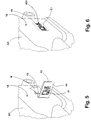
- einen Ausschnitt des in der mit der gemäß
Fig. 4 ausgebildeten Stirnseitenwand versehenen Gießform gemäßFig. 1 gegossenen Gussteils vor dem Putzen in perspektivischer Ansicht; - Fig. 6
- den Ausschnitt gemäß
Fig. 5 nach dem Putzen; - Fig. 7
- ein streifenförmiges zweites Kennzeichenelement in einer frontalen Ansicht auf seine eine Oberfläche;
- Fig. 8
- das Kennzeichenelement gemäß
Fig. 7 in einer frontalen Ansicht auf seine andere Oberfläche; - Fig. 9
- den Stirnseitenwandkern der Gießform gemäß
Fig. 4 mit dem inFig. 7 und 8 dargestellten Kennzeichenelement in einer frontalen Ansicht auf seine dem Formhohlraum der Gießform zugeordneten Seite; - Fig. 10
- einen Ausschnitt des in der mit der gemäß
Fig. 9 ausgebildeten Stirnseitenwand versehenen Gießform gemäßFig. 1 gegossenen Gussteils vor dem Putzen in perspektivischer Ansicht; - Fig. 11
- den Ausschnitt gemäß
Fig. 10 nach dem Putzen. - Die in
Fig. 1 dargestellte Gießform 1 zum Gießen eines Gussteils G1,G2, bei dem es sich hier um ein Kurbelgehäuse für einen Verbrennungsmotor handelt, ist in konventioneller Weise als Kernpaket mit einem Bodenkern 2, einem Deckelkern 3, Längsseitenwandkernen 4a,4b und Stirnseitenwandkernen 5,6 ausgebildet. Die hier jeweils als Baueinheit dargestellten Kerne 2-6 können selbstverständlich in an sich bekannter Weise wiederum aus zwei oder mehr Einzelkernen zusammengesetzt sein. - An den Kernen 2-6 der Gießform 1 des weiteren hier der Übersichtlichkeit halber nicht dargestellten Speiser, Zuläufe, Anschnitte und desgleichen ausgebildet, über die ein von der Gießform 1 umschlossener Formhohlraum 7 mit Metallschmelze befüllt werden kann. Bei der Metallschmelze handelt es sich hier beispielsweise um eine konventionelle Aluminium-Gusslegierung.
- Im Formhohlraum 7 sind weitere Gießkerne 8 und Einsätze 9 angeordnet, welche in ebenso an sich bekannter Weise im Gussteil G1,G2 Zylinder, Öl- und Wasserkanäle etc. abbilden.
- Der Bodenkern 2 der Gießform 1 kann aus einem Metallwerkstoff hergestellt und wiederverwendbar sein. Dagegen sind die anderen Gießkerne 3-6,8 der Gießform 1 aus zu diesem Zweck bekanntem Formstoff hergestellt und werden bei der Entformung des Gussteils G1,G2 zerstört.
- An einer dem Formhohlraum 7 zugeordneten Fläche 10 der Stirnseitenwand 5 ist ein nach Art eines Winkelstücks ausgebildetes Kennzeichenelement 11 angeordnet, das aus einem Stahlblechstreifen gekantet worden ist.
- Das Kennzeichenelement 11 weist zwei rechtwinklig zueinander angeordnete Schenkel 12,13 auf, die auf ihrer vom zwischen ihnen eingeschlossenen Winkel β jeweils abgewandten Seite jeweils eine ebene Außenfläche aufweisen. Die betreffende Außenfläche des Schenkels 12 bildet dabei eine dem Formhohlraum 7 und damit dem jeweils zu gießenden Gussteil G1,G2 zugeordnete Gussteilfläche 14, wogegen die rechtwinklig dazu angeordnete Außenfläche des zweiten Schenkels 13 eine Informationsfläche 15 bildet. Sowohl an der Gussteilfläche 14 als auch an der Informationsfläche 15 ist jeweils als DMC codierte Information I1, I2 dargestellt. Die Darstellung der Information I1, I2 erfolgt dabei jeweils durch in die jeweilige Fläche einprägte, der DMC-Codierung entsprechend angeordnete nach kalottenartige Vertiefungen V1, V2 von etwa 1 mm Durchmesser.
- Vor dem Abguss des Gussteils G1 steckt der Schenkel 13 des Kennzeichenelements 11, der die Informationsfläche 15 mit der Information I2 aufweist, in einer in die Fläche 10 des Stirnwandseitenkerns 5 eingeformten schlitzförmigen Aufnahme 16. Der Sitz des Schenkels 13 in der Aufnahme 16 ist dabei so passgenau, dass beim Abgießen keine Metallschmelze in die Aufnahme gelangt, insbesondere die Informationsfläche 15 im Bereich der dort angeordneten Information I2 nicht mit Metallschmelze benetzt wird. Gleichzeitig ist der Schenkel 13 soweit in die Aufnahme 16 geschoben, dass der andere Schenkel 12 des Kennzeichenelements 11 mit seiner von der Gussteilfläche 14 abgewandten Fläche 17 weitestgehend dicht an der Fläche 10 des Stirnseitenwandkerns 5 anliegt.
- Beim Abgießen der Metallschmelze in den Formhohlraum 7 der Gießform 1 umströmt die Metallschmelze den Schenkel 12 des Kennzeichenelements 11, so dass einerseits die als Information I1 die Gussteilfläche 14 eingeformten Vertiefungen V1 mit Metallschmelze gefüllt werden und anderseits die Metallschmelze die Ränder des Schenkels 12 umfasst.
- Spätestens mit dem Ende des Abgießens setzt die Erstarrung der in die Gießform 1 gefüllten Metallschmelze ein.
- Bereits vor der vollständigen Erstarrung des Gussteils G1 kann die Gießform 1 in an sich bekannter Weise in einen Wärmebehandlungsofen gefördert werden, in dem durch Wärmezufuhr der Zerfall der Gießform 1 gefördert und gleichzeitig eine Wärmebehandlung des Gussteils G1 erfolgt. Selbstverständlich kann das Gussteil G1 auch auf jede andere Weise erstarren und anschließend entformt werden.
- Nach der Erstarrung und Entformung des Gussteils G1 sitzt das Kennzeichenelement 11 fest an der Fläche 18 des Gussteils G1, die durch die Fläche 10 des Stirnseitenwandkerns 5 am Gussteil G1 abgebildet ist. Ein mindestens formschlüssiger Halt des Kennzeichenelements 11 ist dabei durch erstarrte Metallschmelze M gesichert, die beim Abguss um die Ränder des Schenkels 12 geströmt und dabei den Schenkel 12 teilweise hinterlaufen hat und so den Schenkel 12 umklammert. Dagegen ist der an seiner Informationsfläche 15 die Information I1 tragende Schenkel 13 von Metallschmelze unbenetzt geblieben. Dementsprechend kann nun die Information I1 problemlos durch eine entsprechende hier nicht gezeigte Leseeinrichtung erfasst und alle für die Qualitätssicherung und Fehlernachverfolgung notwendigen Prozessdaten anhand der Information I1 in einer Datenbank dem Gussteil G1 zugeordnet werden.
- Im weiteren durchläuft das Gussteil G1 eine mechanische Nachbehandlung ("Putzen"), in der in bekannter Weise die an ihm haftenden Rückstände der Gießform, die gießtechnisch erforderlichen, jedoch für die Funktion des Gussteils nicht benötigten Formelemente sowie an Stoßstellen von Gießkernen unvermeidliche Nähte und desgleichen vom Gussteil G1 abgetrennt werden. Dabei wird das Gussteil G1 einer abschließenden Sandstrahlbehandlung unterzogen, bei der auch das Kennzeichenelement 11 vom Gussteil G1 abgetrennt und der darunter liegende, bis dahin durch den Schenkel 12 mit seiner an dem Gussteil G1 anliegenden Gussteilfläche 14 abgedeckte Flächenabschnitt 19 des Gussteils G1 freigelegt.
- An dem Flächenabschnitt 19 ist nun dauerhaft die zuvor an der Gussteilfläche 14 durch die dort eingeprägten Vertiefungen V1 dargestellte Information I1 in eines entsprechenden Musters von punktartigen Erhebungen E1 abgebildet. Die so an dem Gussteil G1 ausgebildete Information IG1 kann jederzeit erneut ausgelesen werden, so dass auch nach einer langen Gebrauchsdauer des Gussteils G1 noch exakt festgestellt werden kann, wie das Gussteil G1 hergestellt worden ist und welche Verfahrensparameter dabei eingestellt worden sind.
- Im Unterschied zur voranstehend erläuterten Herstellung des Gussteils G1 ist bei der Erzeugung des Gussteils G2 ein streifenförmiges, ebenfalls aus Blechmaterial hergestelltes Kennzeichenelement 20 zum Einsatz gekommen.
- Die eine Oberfläche des Kennzeichenelements 20 dient dabei als Gussteilfläche 21, wogegen die an der gegenüberliegenden Seite des Kennzeichenelements 20 vorhandene Oberfläche als Informationsfläche 22 dient. Die Informationsfläche 22 und die Gussteilfläche 21 sind dabei bezogen auf die Längserstreckung L des Kennzeichenelements 20 in zwei Längshälften L1,L2 geteilt. Die Informationsfläche 22 trägt in ihrer Längshälfte L1 die ihr zugeordnete Information I1, wogegen die Gussteilfläche 21 in ihrer Längshälfte L2 die ihr zugeordnete Information I2 trägt. Bezogen auf die Längserstreckung L sind die Informationen I1,I2 von Informationsfläche 22 und Gussteilfläche 21 somit versetzt zueinander angeordnet. Die Informationen I1,I2 sind wie beim Kennzeichenelement 11 durch in die jeweilige Fläche 21,22 eingeformte Vertiefungen V1,V2 dargestellt.
- Das Kennzeichenelement 20 ist ebenfalls an der Fläche 10 des Stirnwandseitenkerns 5 angeordnet. Zu diesem Zweck ist in diesem Fall dort eine Aufnahme 23 eingeformt, deren Form und Abmessungen an das Kennzeichenelement 20 so angepasst ist, dass das Kennzeichenelement 20 dicht an der ebenen Grundfläche der Aufnahme 23 anliegt und die Ränder des Kennzeichenelements 20 beim Abgießen leicht von der das Kennzeichenelement 20 anströmenden Schmelze penetriert werden können.
- Nach dem Abguss und dem Erstarren der Metallschmelze zu dem Gussteil G2 umklammert das erstarrte Gussmetall die Ränder des Kennzeichenelements 20, so dass dieses nach dem Entformen ebenfalls mindestens durch Formschluss sicher und fest an dem Gussteil G2 gehalten ist. Die an der nun dicht am Gussteil G2 anliegenden Gussteilfläche 21 des Kennzeichenelements 20 vorhandene Information I2 ist dabei wie beim Gussteil G1 in den vom Kennzeichenelement 20 abgedeckten Flächenabschnitt 24 des Gussteil G2 eingestempelt worden, wogegen die an der nun frei liegenden Informationsfläche 22 des Kennzeichenelements 21 vorgesehene Information I1 frei liegt und durch eine Leseeinrichtung erfassbar ist.
- Beim abschließenden Putzen des Gussteils G2 wird auch das Kennzeichenelement 20 entfernt und dadurch der zuvor von ihm abgedeckte Flächenabschnitt 24 des Gussteils G2 mit der daran abgebildeten, durch Erhebungen E2 dargestellte Information IG2 freigelegt.
- Mit der Erfindung steht somit ein Verfahren zur Verfügung, mit dem sich dauerhaft mit lesbarer Information IG1,IG2 versehene Gussteile G1,G2 herstellen lassen. Dazu wird ein Kennzeichenelement 11,20, das an einer Seite eine mit Information I1,I2 versehene Informationsfläche 15,22 und an einer anderen Seite eine dem Gussteil G1,G2 zugeordnete, ebenfalls mit Information I1,I2 versehene Gussteilfläche 14,21 aufweist, an einer einem Formhohlraum 7 einer Gießform 1 zugeordneten Gießformfläche 10 so angeordnet, dass die Informationsfläche 15,22 abgedeckt ist, während die Gussteilfläche 14,21 des Kennzeichenelements 11,20 frei im Formhohlraum 7 liegt. Dann wird eine Metallschmelze M unter Benetzung der Gussteilfläche 14,21 in die Gießform 1 gegossen, so dass während des Abgießens oder Erstarrens der Metallschmelze M eine stoff-, form- oder kraftschlüssige Anbindung des Kennzeichenelements 11,20 an das Gussteil G1,G2 entsteht und sich die an der Gussteilfläche 14,21 vorhandene Information I1,I2 an der zugeordneten Fläche 18 des Gussteils G1,G2 nach Art eines Stempels abbildet. Schließlich wird das Gussteil G1,G2 aus der Gießform 1 entformt und in konventioneller Weise geputzt.
-
- 1
- Gießform zum Gießen eines Gussteils G1, G2
- 2
- Bodenkern der Gießform 1
- 3
- Deckelkern der Gießform 1
- 4a, 4b
- Längsseitenwandkerne der Gießform 1
- 5, 6
- Stirnseitenwandkerne der Gießform 1
- 7
- Formhohlraum der Gießform 1
- 8
- Gießkerne der Gießform 1
- 9
- Einsätze der Gießform 1
- 10
- dem Formhohlraum 7 zugeordnete Fläche der Stirnseitenwand 5
- 11
- Kennzeichenelement
- 12, 13
- Schenkel des Kennzeichenelements 11
- 14
- Gussteilfläche des Kennzeichenelements 11
- 15
- Informationsfläche des Kennzeichenelements 11
- 16
- Aufnahme in der Fläche 10
- 17
- von der Gussteilfläche 14 abgewandte Fläche des Schenkels 12
- 18
- durch die Fläche 10 des Stirnseitenwandkerns 5 am Gussteil G1 abgebildete Fläche
- 19
- durch den Schenkel 12 mit seiner an dem Gussteil G1 anliegenden Gussteilfläche 14 abgedeckter Flächenabschnitt des Gussteils G1
- β
- Winkel zwischen den Schenkeln 12, 13
- E1
- die Information IG1 darstellende Erhebungen
- G1
- Gussteil
- I1, I2
- Information
- IG1
- Information am Gussteil G1
- M
- erstarrte Metallschmelze
- V1, V2
- Vertiefungen
- 20
- Kennzeichenelement
- 21
- Gussteilfläche des Kennzeichenelements 20
- 22
- Informationsfläche des Kennzeichenelements 20
- 23
- Aufnahme
- 24
- vom Kennzeichenelement 20 abgedeckter Flächenabschnitt des Gussteil G2
- E2
- die Information IG2 darstellende Erhebungen
- G2
- Gussteil
- IG2
- Information des Gussteils G2
- L
- Längserstreckung des Kennzeichenelements 20
- L1, L2
- Längshälften des Kennzeichenelements 20
Claims (15)
- Verfahren zur Herstellung eines mit lesbarer Information (IG1,IG2) versehenen Gussteils (G1,G2), umfassend folgende Arbeitsschritte:a) Bereitstellen eines Kennzeichenelements (11, 20),- das an einer Seite eine mit Information (I1, I2) versehene Informationsfläche (15, 22) und- an einer anderen Seite eine dem Gussteil (G1, G2) zugeordnete Gussteilfläche (14, 21) aufweist, an der ebenfalls eine Information (I1, I2) vorhanden ist;b) Anordnen des Kennzeichenelements (11, 20) in einer Gießform (1), die einen das zu gießende Gussteil (G1, G2) abbildenden Formhohlraum (7) umgrenzt, wobei das Kennzeichenelement (11, 20) an einer dem Formhohlraum (7) zugeordneten Gießformfläche (10) derart angeordnet wird, dass die Informationsfläche (15, 22) gegenüber dem Formhohlraum (7) abgedeckt ist, während die Gussteilfläche (14, 21) des Kennzeichenelements (11, 20) frei liegend dem Formhohlraum (7) zugeordnet ist;c) Abgießen einer Metallschmelze (M) in die Gießform (1) unter Benetzung der Gussteilfläche (14, 21) des Kennzeichenelements (11,20) mit Metallschmelze (M) ;d) Erstarren der Metallschmelze (M) zu dem Gussteil (G1,G2), wobei sich während des Abgießens oder des Erstarrens eine stoff-, form- oder kraftschlüssige Anbindung des Kennzeichenelements (11,20) an das Gussteil (G1, G2) ergibt und sich die an der Gussteilfläche (14, 21) vorhandene Information (I1, I2) während des Abgießens oder des Erstarrens der Metallschmelze (M) nach Art eines Stempels an der zugeordneten Fläche (18) des Gussteils (G1, G2) abbildet;e) Entformen des Gussteils (G1, G2) aus der Gießform (1) ;f) Putzen des Gussteils (G1, G2).
- Verfahren nach Anspruch 1, dadurch gekennzeichnet, dass im Zuge einer Nachbehandlung des Gussteils (G1, G2) das Kennzeichenelement (11, 20) entfernt wird.
- Verfahren nach einem der voranstehenden Ansprüche, dadurch gekennzeichnet, dass das Gussteil (G1,G2) eine Wärmebehandlung durchläuft.
- Verfahren nach einem der voranstehenden Ansprüche, dadurch gekennzeichnet, dass das Gussteil (G1,G2) eine mechanische Nachbehandlung durchläuft, bei der mechanisch auf das Gussteil (G1, G2) eingewirkt wird.
- Verfahren nach einem der voranstehenden Ansprüche, dadurch gekennzeichnet, dass das Kennzeichenelement (20) ein Blechstreifen ist.
- Verfahren nach Anspruch 5, dadurch gekennzeichnet, dass die Information (I1) an der Informationsfläche (22) gegenüber liegend zur Information (I2) an der Gussteilfläche (21) des Kennzeichenelements (20) angeordnet ist.
- Verfahren nach Anspruch 6, dadurch gekennzeichnet, dass die Informationen (I1,I2) an der Informations- (22) und der Gussteilfläche (21) des Kennzeichenelements (20) versetzt zueinander angeordnet sind.
- Verfahren nach einem der Ansprüche 1 bis 4,
dadurch g ekennzeichnet, dass das Kennzeichenelement (11) ein Blechwinkel ist. - Verfahren nach Anspruch 8, dadurch gekennzeichnet, dass das Kennzeichenelement (11) an seinem einen Schenkel (12) die Gussteilfläche (14) und an seinem anderen Schenkel (13) die Informationsfläche (15) aufweist.
- Verfahren nach einem der voranstehenden Ansprüche, dadurch gekennzeichnet, dass mindestens eine der an dem Kennzeichenelement (11, 20) vorgesehenen Informationen (I1, I2) maschinenlesbar ist.
- Verfahren nach Anspruch 10, dadurch gekennzeichnet, dass die maschinenlesbare Information (I1, I2) aus Daten besteht, über die der Zeitpunkt oder die Parameter der gießtechnischen Herstellung des Gussteils (G1, G2) ermittelbar ist.
- Verfahren nach Anspruch 11, dadurch gekennzeichnet, dass der am Gussteil (G1,G2) abgebildeten maschinenlesbaren Information (IG1,IG2) in einer Datenbank abgelegte Daten zugeordnet sind.
- Verfahren nach Anspruch 12, dadurch gekennzeichnet, dass den am Gussteil (G1, G2) abgebildeten maschinenlesbaren Informationen (IG1, IG2) in der Datenbank zugeordneten Daten mit jedem Verfahrensschritt, den das Gussteil (G1, G2) durchläuft, weitere auslesbare Daten zugeordnet werden.
- Verfahren nach einem der voranstehenden Ansprüche, dadurch gekennzeichnet, dass die Gießform (1) mindestens teilweise durch aus einem Formstoff bestehende Kerne (2-6,8) gebildet ist.
- Verfahren nach Anspruch 14, dadurch gekennzeichnet, dass das Kennzeichenelement (11,20) flächenbündig in eine Fläche (10) eines der Gießkerne (2-6,8) eingesetzt ist.
Applications Claiming Priority (2)
| Application Number | Priority Date | Filing Date | Title |
|---|---|---|---|
| DE102015102308.3A DE102015102308A1 (de) | 2015-02-18 | 2015-02-18 | Verfahren zum Kennzeichnen eines Gussteils |
| PCT/IB2016/000076 WO2016132196A1 (de) | 2015-02-18 | 2016-02-02 | Verfahren zum kennzeichnen eines gussteils |
Publications (2)
| Publication Number | Publication Date |
|---|---|
| EP3283246A1 EP3283246A1 (de) | 2018-02-21 |
| EP3283246B1 true EP3283246B1 (de) | 2019-08-07 |
Family
ID=55358015
Family Applications (1)
| Application Number | Title | Priority Date | Filing Date |
|---|---|---|---|
| EP16704474.2A Active EP3283246B1 (de) | 2015-02-18 | 2016-02-02 | Verfahren zum kennzeichnen eines gussteils |
Country Status (7)
| Country | Link |
|---|---|
| US (1) | US10052686B2 (de) |
| EP (1) | EP3283246B1 (de) |
| JP (1) | JP6419975B2 (de) |
| KR (1) | KR101930003B1 (de) |
| CN (1) | CN107249783B (de) |
| DE (1) | DE102015102308A1 (de) |
| WO (1) | WO2016132196A1 (de) |
Families Citing this family (11)
| Publication number | Priority date | Publication date | Assignee | Title |
|---|---|---|---|---|
| DE102018118969A1 (de) * | 2018-08-03 | 2020-02-06 | Zollern Gmbh & Co. Kg | Einzelteilrückverfolgung von Feingussbauteilen und das Bereitstellen von maschinenlesbaren Codes auf Feingussbauteilen |
| DE102019202750B3 (de) * | 2019-02-28 | 2020-03-12 | Fraunhofer-Gesellschaft zur Förderung der angewandten Forschung e.V. | Verfahren zur Kennzeichnung von Metallgussbauteilen mittels elektronischer Transponder |
| FR3094919B1 (fr) * | 2019-04-12 | 2023-04-21 | Renaul S A S | Procédé et outil pour le marquage sur une pièce moulée dans un moule, d’un paramètre lié à l’opération de moulage |
| EP3736064A1 (de) | 2019-05-10 | 2020-11-11 | Disa Industries A/S | Giessereiproduktionslinie und verfahren zum betrieb solch einer giessereiproduktionslinie |
| CN110530411A (zh) * | 2019-07-08 | 2019-12-03 | 金榀精密工业(苏州)有限公司 | 智能来料检测标示系统 |
| CN110508779A (zh) * | 2019-07-08 | 2019-11-29 | 金榀精密工业(苏州)有限公司 | 基于参数转移式的快速标记体系 |
| DE102019007188A1 (de) | 2019-10-16 | 2021-04-22 | Gienanth Gmbh | Vorrichtung und Verfahren zur Qualitätsverbesserung beim automatisierten maschinellen Gussverfahren mittels Identifizierung der Gussteile durch Mustererkennung und Strukturerkennung |
| DE202019004266U1 (de) | 2019-10-16 | 2019-11-07 | Gienanth Gmbh | Vorrichtung zur Qualitätsverbesserung beim Maschinen-Gussverfahren mittels Identifizierung der Gussteile durch Mustererkennung und Strukturerkennung. |
| US11693652B2 (en) | 2021-04-16 | 2023-07-04 | 27 Software U.S. Inc. | Automated authoring of software solutions from a data model |
| DE102022210130A1 (de) | 2022-09-26 | 2024-03-28 | Volkswagen Aktiengesellschaft | Verfahren und Ausleseeinrichtung zum Auslesen eines Datensatzes aus einem Daten-Matrix-Code |
| FR3163588A1 (fr) * | 2024-06-21 | 2025-12-26 | Fonderie Et Mecanique Generale Castelbriantaise | dispositif de marquage d’une pièce de fonderie coulée dans un moule en sable |
Family Cites Families (18)
| Publication number | Priority date | Publication date | Assignee | Title |
|---|---|---|---|---|
| JPS5017018B1 (de) * | 1970-09-10 | 1975-06-18 | ||
| JPS5327576B2 (de) | 1973-06-20 | 1978-08-09 | ||
| US4900637A (en) * | 1988-10-07 | 1990-02-13 | Aluminum Company Of America | Tag for labeling an article cast from molten material, method therefore and article |
| JPH0475761A (ja) | 1990-03-30 | 1992-03-10 | Toto Ltd | 情報マークを有する鋳物製品 |
| CH687130A5 (de) * | 1992-04-10 | 1996-09-30 | Fischer Georg Giessereianlagen | Verfahren und Vorrichtung zur individuellen Kennzeichnung von Nassguss-Sandformen. |
| US5465780A (en) * | 1993-11-23 | 1995-11-14 | Alliedsignal Inc. | Laser machining of ceramic cores |
| CN1204559A (zh) * | 1997-04-24 | 1999-01-13 | 新东工业株式会社 | 测量铸模强度并在铸模上压制标记的装置 |
| US6220333B1 (en) * | 1998-11-06 | 2001-04-24 | Jay S. Cantwell | Bar code stencil and method of use |
| JP2001300690A (ja) * | 2000-04-19 | 2001-10-30 | Hitachi Metals Ltd | 車両用軽合金製ホイールおよびその製造方法 |
| US6582197B2 (en) | 2001-02-22 | 2003-06-24 | Simon E. Coulson | Method of investment casting with casting identification |
| JP4075761B2 (ja) * | 2003-10-10 | 2008-04-16 | 日産自動車株式会社 | 内燃機関の吸気装置 |
| DE102005018936A1 (de) * | 2004-10-08 | 2006-04-20 | Fraunhofer-Gesellschaft zur Förderung der angewandten Forschung e.V. | Gussbauteil mit integrierten Funktionselementen und Verfahren zu seiner Herstellung |
| DE102006030365B3 (de) * | 2006-06-27 | 2007-12-06 | Siemens Ag | Verfahren zum Herstellen eines Gussteiles |
| DE102007035144A1 (de) * | 2007-07-25 | 2009-01-29 | Ralf Bux | Vorrichtung und Verfahren zur Individualisierung bzw. Kennung eines Werkstücks |
| DE102008024906B3 (de) * | 2008-05-23 | 2010-01-07 | Institut für Automatisierung und Informatik GmbH Zentrum für industrielle Forschung und Entwicklung Wernigerode | Verfahren und Vorrichtung zur Markierung von Gussteilen während des Urformprozesses |
| DE202008018295U1 (de) * | 2008-12-03 | 2012-08-06 | Nemak Linz Gmbh | Gusskörper |
| ES2389817T3 (es) * | 2008-12-03 | 2012-11-02 | Nemak Linz Gmbh | Cuerpo de fundición y procedimiento para la fabricación de un cuerpo de fundición |
| US20130220567A1 (en) * | 2012-02-29 | 2013-08-29 | GM Global Technology Operations LLC | System and method for integrally serializing a cast part |
-
2015
- 2015-02-18 DE DE102015102308.3A patent/DE102015102308A1/de not_active Withdrawn
-
2016
- 2016-02-02 JP JP2017535352A patent/JP6419975B2/ja not_active Expired - Fee Related
- 2016-02-02 WO PCT/IB2016/000076 patent/WO2016132196A1/de not_active Ceased
- 2016-02-02 US US15/551,462 patent/US10052686B2/en active Active
- 2016-02-02 EP EP16704474.2A patent/EP3283246B1/de active Active
- 2016-02-02 KR KR1020177023138A patent/KR101930003B1/ko not_active Expired - Fee Related
- 2016-02-02 CN CN201680011093.5A patent/CN107249783B/zh active Active
Non-Patent Citations (1)
| Title |
|---|
| None * |
Also Published As
| Publication number | Publication date |
|---|---|
| CN107249783A (zh) | 2017-10-13 |
| WO2016132196A8 (de) | 2017-08-10 |
| CN107249783B (zh) | 2018-10-19 |
| JP2018507112A (ja) | 2018-03-15 |
| US10052686B2 (en) | 2018-08-21 |
| KR101930003B1 (ko) | 2018-12-17 |
| WO2016132196A1 (de) | 2016-08-25 |
| JP6419975B2 (ja) | 2018-11-07 |
| US20180036795A1 (en) | 2018-02-08 |
| DE102015102308A1 (de) | 2016-08-18 |
| EP3283246A1 (de) | 2018-02-21 |
| KR20170125329A (ko) | 2017-11-14 |
Similar Documents
| Publication | Publication Date | Title |
|---|---|---|
| DE102015102308A1 (de) | Verfahren zum Kennzeichnen eines Gussteils | |
| EP1398098B1 (de) | Verfahren zum Herstellen von Turbinenschaufeln mit darin angeordneten Kühlkanälen | |
| DE10207279A1 (de) | Gießverfahren und Gussteil | |
| DE102007005455A1 (de) | Reifenvulkanisationsform und Verfahren zur Herstellung einer Reifenvulkanisationsform | |
| DE102005047035B3 (de) | Verfahren zur Herstellung eines Kolbens für einen Verbrennungsmotor sowie danach hergestellter Kolben | |
| DE202008018295U1 (de) | Gusskörper | |
| DE102007004050A1 (de) | Vorrichtung und Sandkern zur Herstellung eines Zylinderkurbelgehäuses | |
| EP2196272B1 (de) | Gusskörper und Verfahren zur Herstellung eines Gusskörpers | |
| DE2659190C2 (de) | Tragvorrichtung für ein Modell für Präzisionsgießverfahren | |
| DE19925674B4 (de) | Kennzeichnung von Gußteilen | |
| WO2019120804A1 (de) | Verfahren zum herstellen eines formteils sowie speisereinsatz zur verwendung in einem solchen verfahren | |
| EP3038770B1 (de) | Verfahren zur herstellung von kodierflächen aus einem rohteil | |
| DE102019202750B3 (de) | Verfahren zur Kennzeichnung von Metallgussbauteilen mittels elektronischer Transponder | |
| DE19807404A1 (de) | Tief- und Streckziehwerkzeug mit durch konturgetreu geformte Masken abgedeckten Funktionsflächen und Verfahren zu seiner Herstellung | |
| DE4443475C2 (de) | Verfahren zur Kennzeichnung von Betonkörpern und Formkasten zur Durchführung dieses Verfahrens | |
| DE3112225C2 (de) | Verfahren zum Herstellen von Formwerkzeugen | |
| AT519404B1 (de) | Verfahren zur Sicherung eines RFID-Chips sowie Stempelplatte | |
| DE888602C (de) | Verfahren zur Herstellung von Dauerformen oder Modelleinrichtungen | |
| DE3733128C1 (en) | Method for keeping core exit surfaces of ceramic hollow bodies provided with sand cores free from core sand | |
| DE102004034802B4 (de) | Metallische Dauerform zur Herstellung von Großgussteilen aus Metalllegierungen | |
| DE69810514T2 (de) | Fliesskanalblock und verfahren zu dessen herstellung | |
| DE2043216C (de) | Vorrichtung zum automatischen Herstellen von Formmasken mit einstückig angeformtem Eingußtrichter | |
| DE3041999A1 (de) | Mehrteilige dauergiessform (kokille) | |
| DE7431729U (de) | Formplatte | |
| DE102018128021A1 (de) | Kokille sowie Verfahren zum Herstellen eines Kurbelgehäuses |
Legal Events
| Date | Code | Title | Description |
|---|---|---|---|
| STAA | Information on the status of an ep patent application or granted ep patent |
Free format text: STATUS: THE INTERNATIONAL PUBLICATION HAS BEEN MADE |
|
| PUAI | Public reference made under article 153(3) epc to a published international application that has entered the european phase |
Free format text: ORIGINAL CODE: 0009012 |
|
| STAA | Information on the status of an ep patent application or granted ep patent |
Free format text: STATUS: REQUEST FOR EXAMINATION WAS MADE |
|
| 17P | Request for examination filed |
Effective date: 20170714 |
|
| AK | Designated contracting states |
Kind code of ref document: A1 Designated state(s): AL AT BE BG CH CY CZ DE DK EE ES FI FR GB GR HR HU IE IS IT LI LT LU LV MC MK MT NL NO PL PT RO RS SE SI SK SM TR |
|
| AX | Request for extension of the european patent |
Extension state: BA ME |
|
| DAV | Request for validation of the european patent (deleted) | ||
| DAX | Request for extension of the european patent (deleted) | ||
| GRAP | Despatch of communication of intention to grant a patent |
Free format text: ORIGINAL CODE: EPIDOSNIGR1 |
|
| STAA | Information on the status of an ep patent application or granted ep patent |
Free format text: STATUS: GRANT OF PATENT IS INTENDED |
|
| INTG | Intention to grant announced |
Effective date: 20180629 |
|
| GRAJ | Information related to disapproval of communication of intention to grant by the applicant or resumption of examination proceedings by the epo deleted |
Free format text: ORIGINAL CODE: EPIDOSDIGR1 |
|
| STAA | Information on the status of an ep patent application or granted ep patent |
Free format text: STATUS: REQUEST FOR EXAMINATION WAS MADE |
|
| GRAS | Grant fee paid |
Free format text: ORIGINAL CODE: EPIDOSNIGR3 |
|
| STAA | Information on the status of an ep patent application or granted ep patent |
Free format text: STATUS: GRANT OF PATENT IS INTENDED |
|
| GRAP | Despatch of communication of intention to grant a patent |
Free format text: ORIGINAL CODE: EPIDOSNIGR1 |
|
| INTC | Intention to grant announced (deleted) | ||
| INTG | Intention to grant announced |
Effective date: 20181206 |
|
| GRAJ | Information related to disapproval of communication of intention to grant by the applicant or resumption of examination proceedings by the epo deleted |
Free format text: ORIGINAL CODE: EPIDOSDIGR1 |
|
| GRAL | Information related to payment of fee for publishing/printing deleted |
Free format text: ORIGINAL CODE: EPIDOSDIGR3 |
|
| STAA | Information on the status of an ep patent application or granted ep patent |
Free format text: STATUS: REQUEST FOR EXAMINATION WAS MADE |
|
| INTC | Intention to grant announced (deleted) | ||
| GRAP | Despatch of communication of intention to grant a patent |
Free format text: ORIGINAL CODE: EPIDOSNIGR1 |
|
| STAA | Information on the status of an ep patent application or granted ep patent |
Free format text: STATUS: GRANT OF PATENT IS INTENDED |
|
| INTG | Intention to grant announced |
Effective date: 20190307 |
|
| GRAA | (expected) grant |
Free format text: ORIGINAL CODE: 0009210 |
|
| STAA | Information on the status of an ep patent application or granted ep patent |
Free format text: STATUS: THE PATENT HAS BEEN GRANTED |
|
| AK | Designated contracting states |
Kind code of ref document: B1 Designated state(s): AL AT BE BG CH CY CZ DE DK EE ES FI FR GB GR HR HU IE IS IT LI LT LU LV MC MK MT NL NO PL PT RO RS SE SI SK SM TR |
|
| REG | Reference to a national code |
Ref country code: GB Ref legal event code: FG4D Free format text: NOT ENGLISH |
|
| REG | Reference to a national code |
Ref country code: CH Ref legal event code: EP Ref country code: AT Ref legal event code: REF Ref document number: 1163061 Country of ref document: AT Kind code of ref document: T Effective date: 20190815 |
|
| REG | Reference to a national code |
Ref country code: DE Ref legal event code: R096 Ref document number: 502016005923 Country of ref document: DE |
|
| REG | Reference to a national code |
Ref country code: IE Ref legal event code: FG4D Free format text: LANGUAGE OF EP DOCUMENT: GERMAN |
|
| REG | Reference to a national code |
Ref country code: NL Ref legal event code: MP Effective date: 20190807 |
|
| REG | Reference to a national code |
Ref country code: LT Ref legal event code: MG4D |
|
| PG25 | Lapsed in a contracting state [announced via postgrant information from national office to epo] |
Ref country code: LT Free format text: LAPSE BECAUSE OF FAILURE TO SUBMIT A TRANSLATION OF THE DESCRIPTION OR TO PAY THE FEE WITHIN THE PRESCRIBED TIME-LIMIT Effective date: 20190807 Ref country code: HR Free format text: LAPSE BECAUSE OF FAILURE TO SUBMIT A TRANSLATION OF THE DESCRIPTION OR TO PAY THE FEE WITHIN THE PRESCRIBED TIME-LIMIT Effective date: 20190807 Ref country code: PT Free format text: LAPSE BECAUSE OF FAILURE TO SUBMIT A TRANSLATION OF THE DESCRIPTION OR TO PAY THE FEE WITHIN THE PRESCRIBED TIME-LIMIT Effective date: 20191209 Ref country code: NO Free format text: LAPSE BECAUSE OF FAILURE TO SUBMIT A TRANSLATION OF THE DESCRIPTION OR TO PAY THE FEE WITHIN THE PRESCRIBED TIME-LIMIT Effective date: 20191107 Ref country code: BG Free format text: LAPSE BECAUSE OF FAILURE TO SUBMIT A TRANSLATION OF THE DESCRIPTION OR TO PAY THE FEE WITHIN THE PRESCRIBED TIME-LIMIT Effective date: 20191107 Ref country code: SE Free format text: LAPSE BECAUSE OF FAILURE TO SUBMIT A TRANSLATION OF THE DESCRIPTION OR TO PAY THE FEE WITHIN THE PRESCRIBED TIME-LIMIT Effective date: 20190807 Ref country code: NL Free format text: LAPSE BECAUSE OF FAILURE TO SUBMIT A TRANSLATION OF THE DESCRIPTION OR TO PAY THE FEE WITHIN THE PRESCRIBED TIME-LIMIT Effective date: 20190807 Ref country code: FI Free format text: LAPSE BECAUSE OF FAILURE TO SUBMIT A TRANSLATION OF THE DESCRIPTION OR TO PAY THE FEE WITHIN THE PRESCRIBED TIME-LIMIT Effective date: 20190807 |
|
| PG25 | Lapsed in a contracting state [announced via postgrant information from national office to epo] |
Ref country code: GR Free format text: LAPSE BECAUSE OF FAILURE TO SUBMIT A TRANSLATION OF THE DESCRIPTION OR TO PAY THE FEE WITHIN THE PRESCRIBED TIME-LIMIT Effective date: 20191108 Ref country code: ES Free format text: LAPSE BECAUSE OF FAILURE TO SUBMIT A TRANSLATION OF THE DESCRIPTION OR TO PAY THE FEE WITHIN THE PRESCRIBED TIME-LIMIT Effective date: 20190807 Ref country code: IS Free format text: LAPSE BECAUSE OF FAILURE TO SUBMIT A TRANSLATION OF THE DESCRIPTION OR TO PAY THE FEE WITHIN THE PRESCRIBED TIME-LIMIT Effective date: 20191207 Ref country code: RS Free format text: LAPSE BECAUSE OF FAILURE TO SUBMIT A TRANSLATION OF THE DESCRIPTION OR TO PAY THE FEE WITHIN THE PRESCRIBED TIME-LIMIT Effective date: 20190807 Ref country code: AL Free format text: LAPSE BECAUSE OF FAILURE TO SUBMIT A TRANSLATION OF THE DESCRIPTION OR TO PAY THE FEE WITHIN THE PRESCRIBED TIME-LIMIT Effective date: 20190807 Ref country code: LV Free format text: LAPSE BECAUSE OF FAILURE TO SUBMIT A TRANSLATION OF THE DESCRIPTION OR TO PAY THE FEE WITHIN THE PRESCRIBED TIME-LIMIT Effective date: 20190807 |
|
| PG25 | Lapsed in a contracting state [announced via postgrant information from national office to epo] |
Ref country code: TR Free format text: LAPSE BECAUSE OF FAILURE TO SUBMIT A TRANSLATION OF THE DESCRIPTION OR TO PAY THE FEE WITHIN THE PRESCRIBED TIME-LIMIT Effective date: 20190807 |
|
| PG25 | Lapsed in a contracting state [announced via postgrant information from national office to epo] |
Ref country code: DK Free format text: LAPSE BECAUSE OF FAILURE TO SUBMIT A TRANSLATION OF THE DESCRIPTION OR TO PAY THE FEE WITHIN THE PRESCRIBED TIME-LIMIT Effective date: 20190807 Ref country code: RO Free format text: LAPSE BECAUSE OF FAILURE TO SUBMIT A TRANSLATION OF THE DESCRIPTION OR TO PAY THE FEE WITHIN THE PRESCRIBED TIME-LIMIT Effective date: 20190807 Ref country code: IT Free format text: LAPSE BECAUSE OF FAILURE TO SUBMIT A TRANSLATION OF THE DESCRIPTION OR TO PAY THE FEE WITHIN THE PRESCRIBED TIME-LIMIT Effective date: 20190807 Ref country code: EE Free format text: LAPSE BECAUSE OF FAILURE TO SUBMIT A TRANSLATION OF THE DESCRIPTION OR TO PAY THE FEE WITHIN THE PRESCRIBED TIME-LIMIT Effective date: 20190807 Ref country code: PL Free format text: LAPSE BECAUSE OF FAILURE TO SUBMIT A TRANSLATION OF THE DESCRIPTION OR TO PAY THE FEE WITHIN THE PRESCRIBED TIME-LIMIT Effective date: 20190807 |
|
| PG25 | Lapsed in a contracting state [announced via postgrant information from national office to epo] |
Ref country code: SK Free format text: LAPSE BECAUSE OF FAILURE TO SUBMIT A TRANSLATION OF THE DESCRIPTION OR TO PAY THE FEE WITHIN THE PRESCRIBED TIME-LIMIT Effective date: 20190807 Ref country code: IS Free format text: LAPSE BECAUSE OF FAILURE TO SUBMIT A TRANSLATION OF THE DESCRIPTION OR TO PAY THE FEE WITHIN THE PRESCRIBED TIME-LIMIT Effective date: 20200224 Ref country code: SM Free format text: LAPSE BECAUSE OF FAILURE TO SUBMIT A TRANSLATION OF THE DESCRIPTION OR TO PAY THE FEE WITHIN THE PRESCRIBED TIME-LIMIT Effective date: 20190807 Ref country code: CZ Free format text: LAPSE BECAUSE OF FAILURE TO SUBMIT A TRANSLATION OF THE DESCRIPTION OR TO PAY THE FEE WITHIN THE PRESCRIBED TIME-LIMIT Effective date: 20190807 |
|
| REG | Reference to a national code |
Ref country code: DE Ref legal event code: R097 Ref document number: 502016005923 Country of ref document: DE |
|
| PLBE | No opposition filed within time limit |
Free format text: ORIGINAL CODE: 0009261 |
|
| STAA | Information on the status of an ep patent application or granted ep patent |
Free format text: STATUS: NO OPPOSITION FILED WITHIN TIME LIMIT |
|
| PG2D | Information on lapse in contracting state deleted |
Ref country code: IS |
|
| 26N | No opposition filed |
Effective date: 20200603 |
|
| PG25 | Lapsed in a contracting state [announced via postgrant information from national office to epo] |
Ref country code: SI Free format text: LAPSE BECAUSE OF FAILURE TO SUBMIT A TRANSLATION OF THE DESCRIPTION OR TO PAY THE FEE WITHIN THE PRESCRIBED TIME-LIMIT Effective date: 20190807 |
|
| REG | Reference to a national code |
Ref country code: CH Ref legal event code: PL |
|
| GBPC | Gb: european patent ceased through non-payment of renewal fee |
Effective date: 20200202 |
|
| REG | Reference to a national code |
Ref country code: BE Ref legal event code: MM Effective date: 20200229 |
|
| PG25 | Lapsed in a contracting state [announced via postgrant information from national office to epo] |
Ref country code: LU Free format text: LAPSE BECAUSE OF NON-PAYMENT OF DUE FEES Effective date: 20200202 Ref country code: MC Free format text: LAPSE BECAUSE OF FAILURE TO SUBMIT A TRANSLATION OF THE DESCRIPTION OR TO PAY THE FEE WITHIN THE PRESCRIBED TIME-LIMIT Effective date: 20190807 |
|
| PG25 | Lapsed in a contracting state [announced via postgrant information from national office to epo] |
Ref country code: LI Free format text: LAPSE BECAUSE OF NON-PAYMENT OF DUE FEES Effective date: 20200229 Ref country code: CH Free format text: LAPSE BECAUSE OF NON-PAYMENT OF DUE FEES Effective date: 20200229 |
|
| PG25 | Lapsed in a contracting state [announced via postgrant information from national office to epo] |
Ref country code: IE Free format text: LAPSE BECAUSE OF NON-PAYMENT OF DUE FEES Effective date: 20200202 Ref country code: GB Free format text: LAPSE BECAUSE OF NON-PAYMENT OF DUE FEES Effective date: 20200202 Ref country code: FR Free format text: LAPSE BECAUSE OF NON-PAYMENT OF DUE FEES Effective date: 20200229 |
|
| PG25 | Lapsed in a contracting state [announced via postgrant information from national office to epo] |
Ref country code: BE Free format text: LAPSE BECAUSE OF NON-PAYMENT OF DUE FEES Effective date: 20200229 |
|
| REG | Reference to a national code |
Ref country code: AT Ref legal event code: MM01 Ref document number: 1163061 Country of ref document: AT Kind code of ref document: T Effective date: 20210202 |
|
| PG25 | Lapsed in a contracting state [announced via postgrant information from national office to epo] |
Ref country code: AT Free format text: LAPSE BECAUSE OF NON-PAYMENT OF DUE FEES Effective date: 20210202 |
|
| PG25 | Lapsed in a contracting state [announced via postgrant information from national office to epo] |
Ref country code: MT Free format text: LAPSE BECAUSE OF FAILURE TO SUBMIT A TRANSLATION OF THE DESCRIPTION OR TO PAY THE FEE WITHIN THE PRESCRIBED TIME-LIMIT Effective date: 20190807 Ref country code: CY Free format text: LAPSE BECAUSE OF FAILURE TO SUBMIT A TRANSLATION OF THE DESCRIPTION OR TO PAY THE FEE WITHIN THE PRESCRIBED TIME-LIMIT Effective date: 20190807 |
|
| PG25 | Lapsed in a contracting state [announced via postgrant information from national office to epo] |
Ref country code: MK Free format text: LAPSE BECAUSE OF FAILURE TO SUBMIT A TRANSLATION OF THE DESCRIPTION OR TO PAY THE FEE WITHIN THE PRESCRIBED TIME-LIMIT Effective date: 20190807 |
|
| PGFP | Annual fee paid to national office [announced via postgrant information from national office to epo] |
Ref country code: DE Payment date: 20260217 Year of fee payment: 11 |