EP2196386A2 - Véhicule de type motocyclette - Google Patents
Véhicule de type motocyclette Download PDFInfo
- Publication number
- EP2196386A2 EP2196386A2 EP10003570A EP10003570A EP2196386A2 EP 2196386 A2 EP2196386 A2 EP 2196386A2 EP 10003570 A EP10003570 A EP 10003570A EP 10003570 A EP10003570 A EP 10003570A EP 2196386 A2 EP2196386 A2 EP 2196386A2
- Authority
- EP
- European Patent Office
- Prior art keywords
- suspension
- steering
- vehicle
- swing arm
- arm
- Prior art date
- Legal status (The legal status is an assumption and is not a legal conclusion. Google has not performed a legal analysis and makes no representation as to the accuracy of the status listed.)
- Granted
Links
Images







Classifications
-
- B—PERFORMING OPERATIONS; TRANSPORTING
- B60—VEHICLES IN GENERAL
- B60G—VEHICLE SUSPENSION ARRANGEMENTS
- B60G3/00—Resilient suspensions for a single wheel
- B60G3/18—Resilient suspensions for a single wheel with two or more pivoted arms, e.g. parallelogram
- B60G3/185—Resilient suspensions for a single wheel with two or more pivoted arms, e.g. parallelogram the arms being essentially parallel to the longitudinal axis of the vehicle
-
- B—PERFORMING OPERATIONS; TRANSPORTING
- B60—VEHICLES IN GENERAL
- B60G—VEHICLE SUSPENSION ARRANGEMENTS
- B60G17/00—Resilient suspensions having means for adjusting the spring or vibration-damper characteristics, for regulating the distance between a supporting surface and a sprung part of vehicle or for locking suspension during use to meet varying vehicular or surface conditions, e.g. due to speed or load
- B60G17/015—Resilient suspensions having means for adjusting the spring or vibration-damper characteristics, for regulating the distance between a supporting surface and a sprung part of vehicle or for locking suspension during use to meet varying vehicular or surface conditions, e.g. due to speed or load the regulating means comprising electric or electronic elements
- B60G17/016—Resilient suspensions having means for adjusting the spring or vibration-damper characteristics, for regulating the distance between a supporting surface and a sprung part of vehicle or for locking suspension during use to meet varying vehicular or surface conditions, e.g. due to speed or load the regulating means comprising electric or electronic elements characterised by their responsiveness, when the vehicle is travelling, to specific motion, a specific condition, or driver input
- B60G17/0162—Resilient suspensions having means for adjusting the spring or vibration-damper characteristics, for regulating the distance between a supporting surface and a sprung part of vehicle or for locking suspension during use to meet varying vehicular or surface conditions, e.g. due to speed or load the regulating means comprising electric or electronic elements characterised by their responsiveness, when the vehicle is travelling, to specific motion, a specific condition, or driver input mainly during a motion involving steering operation, e.g. cornering, overtaking
-
- B—PERFORMING OPERATIONS; TRANSPORTING
- B60—VEHICLES IN GENERAL
- B60G—VEHICLE SUSPENSION ARRANGEMENTS
- B60G21/00—Interconnection systems for two or more resiliently-suspended wheels, e.g. for stabilising a vehicle body with respect to acceleration, deceleration or centrifugal forces
- B60G21/02—Interconnection systems for two or more resiliently-suspended wheels, e.g. for stabilising a vehicle body with respect to acceleration, deceleration or centrifugal forces permanently interconnected
- B60G21/04—Interconnection systems for two or more resiliently-suspended wheels, e.g. for stabilising a vehicle body with respect to acceleration, deceleration or centrifugal forces permanently interconnected mechanically
- B60G21/05—Interconnection systems for two or more resiliently-suspended wheels, e.g. for stabilising a vehicle body with respect to acceleration, deceleration or centrifugal forces permanently interconnected mechanically between wheels on the same axle but on different sides of the vehicle, i.e. the left and right wheel suspensions being interconnected
-
- B—PERFORMING OPERATIONS; TRANSPORTING
- B62—LAND VEHICLES FOR TRAVELLING OTHERWISE THAN ON RAILS
- B62D—MOTOR VEHICLES; TRAILERS
- B62D9/00—Steering deflectable wheels not otherwise provided for
- B62D9/02—Steering deflectable wheels not otherwise provided for combined with means for inwardly inclining vehicle body on bends
-
- B—PERFORMING OPERATIONS; TRANSPORTING
- B62—LAND VEHICLES FOR TRAVELLING OTHERWISE THAN ON RAILS
- B62K—CYCLES; CYCLE FRAMES; CYCLE STEERING DEVICES; RIDER-OPERATED TERMINAL CONTROLS SPECIALLY ADAPTED FOR CYCLES; CYCLE AXLE SUSPENSIONS; CYCLE SIDECARS, FORECARS, OR THE LIKE
- B62K25/00—Axle suspensions
- B62K25/005—Axle suspensions characterised by the axle being supported at one end only
-
- B—PERFORMING OPERATIONS; TRANSPORTING
- B62—LAND VEHICLES FOR TRAVELLING OTHERWISE THAN ON RAILS
- B62K—CYCLES; CYCLE FRAMES; CYCLE STEERING DEVICES; RIDER-OPERATED TERMINAL CONTROLS SPECIALLY ADAPTED FOR CYCLES; CYCLE AXLE SUSPENSIONS; CYCLE SIDECARS, FORECARS, OR THE LIKE
- B62K25/00—Axle suspensions
- B62K25/04—Axle suspensions for mounting axles resiliently on cycle frame or fork
- B62K25/12—Axle suspensions for mounting axles resiliently on cycle frame or fork with rocking arm pivoted on each fork leg
- B62K25/22—Axle suspensions for mounting axles resiliently on cycle frame or fork with rocking arm pivoted on each fork leg with more than one arm on each fork leg
- B62K25/24—Axle suspensions for mounting axles resiliently on cycle frame or fork with rocking arm pivoted on each fork leg with more than one arm on each fork leg for front wheel
-
- B—PERFORMING OPERATIONS; TRANSPORTING
- B62—LAND VEHICLES FOR TRAVELLING OTHERWISE THAN ON RAILS
- B62K—CYCLES; CYCLE FRAMES; CYCLE STEERING DEVICES; RIDER-OPERATED TERMINAL CONTROLS SPECIALLY ADAPTED FOR CYCLES; CYCLE AXLE SUSPENSIONS; CYCLE SIDECARS, FORECARS, OR THE LIKE
- B62K5/00—Cycles with handlebars, equipped with three or more main road wheels
- B62K5/08—Cycles with handlebars, equipped with three or more main road wheels with steering devices acting on two or more wheels
-
- B—PERFORMING OPERATIONS; TRANSPORTING
- B62—LAND VEHICLES FOR TRAVELLING OTHERWISE THAN ON RAILS
- B62K—CYCLES; CYCLE FRAMES; CYCLE STEERING DEVICES; RIDER-OPERATED TERMINAL CONTROLS SPECIALLY ADAPTED FOR CYCLES; CYCLE AXLE SUSPENSIONS; CYCLE SIDECARS, FORECARS, OR THE LIKE
- B62K5/00—Cycles with handlebars, equipped with three or more main road wheels
- B62K5/10—Cycles with handlebars, equipped with three or more main road wheels with means for inwardly inclining the vehicle body on bends
-
- B—PERFORMING OPERATIONS; TRANSPORTING
- B60—VEHICLES IN GENERAL
- B60G—VEHICLE SUSPENSION ARRANGEMENTS
- B60G2300/00—Indexing codes relating to the type of vehicle
- B60G2300/12—Cycles; Motorcycles
- B60G2300/122—Trikes
-
- B—PERFORMING OPERATIONS; TRANSPORTING
- B60—VEHICLES IN GENERAL
- B60G—VEHICLE SUSPENSION ARRANGEMENTS
- B60G2300/00—Indexing codes relating to the type of vehicle
- B60G2300/12—Cycles; Motorcycles
- B60G2300/124—Quads
-
- B—PERFORMING OPERATIONS; TRANSPORTING
- B60—VEHICLES IN GENERAL
- B60G—VEHICLE SUSPENSION ARRANGEMENTS
- B60G2800/00—Indexing codes relating to the type of movement or to the condition of the vehicle and to the end result to be achieved by the control action
- B60G2800/01—Attitude or posture control
- B60G2800/012—Rolling condition
Definitions
- the present invention relates to motorcycle-type vehicles of the kind in which the controlling rider controls the angle of lateral tilt by a combination of steering control and balancing body movements.
- motorcycle-type vehicles of the kind in which the controlling rider controls the angle of lateral tilt by a combination of steering control and balancing body movements.
- Conventionally, such vehicles have a single front wheel and a single motor-driven rear wheel.
- such vehicles due to their narrow width can travel through narrow gaps in congested traffic and have good acceleration and fuel economy. If, however, for any reason a tyre on one of the wheels temporarily loses grip the rider may not be able to prevent the vehicle from tipping over.
- a motorcycle-type vehicle comprising a body structure, and rear and front ground-engaging wheels, in which the rear or front wheel or both is or are duplicated to form a pair of wheels, each wheel of the or each pair being connected to the body structure through a suspension having a first end linked to the associated wheel and a second end, the second ends being interconnected by connecting means constraining equal and opposite movements of the said opposite ends relative to the body structure, characterised by stabilizing braking means operable to arrest movements of the said first ends of the suspensions relative to the body structure in the event of excessive lateral acceleration of the vehicle associated with incipient instability and in that limited movement is allowed in the path between each wheel and the body structure in the engaged state of the stabilizing braking means to provide a limited range of suspension.
- a suspension system for a front wheel of a motorcycle-type vehicle comprising a swing arm for the front wheel, the swing arm being pivotally mounted at one end for angular movement about a first transverse axis of the vehicle, a stub axle assembly supporting the other end of the swing arm on its respective wheel, and a parallelogram linkage being formed by the swing arm, an upper arm pivotally mounted at a rear end for angular movement about a second common transverse axis of the vehicle, spaced above the first axis and a strut articulated at its upper end to the upper arm and at its lower end to the said other end of the swing arm.
- This arrangement provides the front wheel with constant trail as the suspension operates.
- the arrangement is particularly suitable for motorcycle-type vehicles having a pair of front wheels, preferably including upper and lower steering rod systems for interconnecting a rider-operated steering control with each stub axle to form an Ackermann-type steering geometry, the upper and lower rod systems being interconnected for the transmission, of torques therebetween along the length direct of the struts.
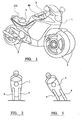
- the motorcycle-type vehicle shown in Figs. 1 and 2 is of generally conventional design insofar as it includes a frame supporting a fairing 1 within which is housed an engine and gearbox (not shown in detail), handlebars 2 for steering the vehicle, a seat 3 for the rider and an additional seat 4 for a pillion passenger.
- the vehicle differs, however, from conventional design in that it has a pair of front wheels 4 and a pair of rear wheels 5.
- the spacing between the pair of front wheels 4 and also the spacing between the rear wheels 5 is sufficiently small to allow them to lie within the overall envelope of the vehicle as can be seen in Fig. 2 .
- each wheel 4, 5 is mounted on the end of a respective swing arm.
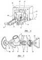
- Fig. 4 shows diagrammatically the arrangement for the rear swing arms 6 which are each independently pivotally mounted at their forward ends on the frame F for pivotal movement about the same transverse axis 7 which is horizontal when the vehicle is upright. At its trailing end, each swing arm 6 carries an axle 8 in which the respective rear wheel 5 is mounted.
- each swing arm 6 (here shown as being of tubular form) is secured to a cylindrical boss 9 formed with an internal bore 10 by means of which it is pivotally mounted on a shaft 11 which in turn is pivotally mounted in lugs 12 secured to the frame F.
- the boss 9 At its outer end (relative to the vehicle) the boss 9 is formed with a pair of dogs 13 interposed (with substantial angular clearance) between a pair of dogs 14 carried by a disc 15 secured to the shaft 11.
- the dogs 13 and 14 thus provide a lost-motion connection between the swing arm 6 and the shaft 11.
- Cushioning elements 16, for example, of rubber, may be interposed between the dogs 13 and 14. These are retained by a cylindrical sleeve portion 17 of the disc 15.
- the inner end of the shaft 11 carries a disc sector 21 which forms part of the disc brake assembly including a brake caliper 22 ( Fig. 4 ) which can be engaged to arrest the disc 21 and shaft 11 and thereby limit the swinging movement of the swing arm 6 to the small range permitted by the clearance between the dogs 13 and 14 as further limited by the cushioning elements 16.
- each of the rear swing arm 6 is articulated to the lower end of a conventional suspension strut 25 at a point near but spaced from the axis 7.
- the upper ends of the two suspension struts 25 are articulated to the opposite ends of a beam 26 which is pivoted at its mid point on a shaft 27 carried by the frame F.
- Each suspension strut 25 is of the conventional kind having an internal spring and damping arrangement.
- the brake 22 is disengaged so that the swing arms 6 are free to swing up and down under the control of the two suspension struts 2.5 and the beam 26.
- the suspension can accommodate a bump 28 encountered by one wheel as shown in Fig. 5 .
- the rider can lean at an appropriate angle when rounding a bend. If, however, the wheels lose their grip on the ground, the brake caliper 22 can be quickly energised to arrest the two brake discs 21, for example, the position shown in Fig. 6 so that the vehicle is then prevented from tipping over further, apart from the small movement allowed by the lost motion connection 13, 14, 16.
- Figs. 8a-c show the response of the suspension shown in Figs. 1-7 to three different road surface situations.
- Fig. 8a shows a smooth road surface with the two spring units 25 equally compressed.
- Fig. 8b only the right-hand wheel has encountered a bump in the road surface (hereinafter referred to as a b situation) resulting in the beam 26 turning through a sufficient angle to cause approximately equal compression in the two spring units 25 which are thus acting in series.
- both wheels meet a bump of corresponding height as shown in Fig. c (hereinafter referred to as a c situation)
- both wheels are raised simultaneously thereby compressing both suspension units 25 equally without turning the beam 26 about its pivot 27.
- the two spring units act in parallel giving an effective spring rate approximately four times greater than that in the case of Fig. 8b .
- Fig. 9 may be used.
- the swing arms 6 are connected to the respective ends of the balance beam 26 by links 31 of constant length having a ball joint 32, 33 at each end.
- the pivot 27 or the balance beam 26 is movable along a rectilinear guide way 34 secured to the vehicle frame.
- a single suspension unit 35 acts between the movable pivot 27 and the frame of the vehicle.
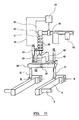
- a hydraulic ram 41 is interposed between the spring unit 35 and the vehicle frame.
- the pivot 27 of the balance beam 26 is carried by a cross-head 42 which is slidable on one or a pair of guide rods 43 secured to the vehicle.
- the ram 41 is supplied with hydraulic fluid by a pump 42 and a valve 43 which is under the control of a processor 44, a sensor 45 measures the extension of the ram 41 and supplies a corresponding signal to the processor 44 along the line 46.
- a further linear sensor 47 determines the position of the cross-head 42 and thus of the pivot 27 and delivers a corresponding signal to the processor 44 along a line 48.
- the processor 44 determines the acceleration of the pivot point 27 by analysis of the output signal from the sensor 47 and thus can cause the ram 41 to be extended in the event of detention of a b type situation.
- the inventor acknowledges the help given by Dr. Y. H. Au and Dr. S. Sivaloganathan of Brunel University in verifying the feasibility of this arrangement.
- the incorporation of the hydraulic ram 41 has other advantages. It can be used to ensure a constant ride height of the vehicle despite variations in the load being carried. By the provision of a suitable rider-operated control, the rider can raise the ride height when traversing rough terrain. The rider may reduce the ride height when travelling in slippery conditions. The ride height may be automatically reduced when the suspension locking brake is engaged. This could be modified in accordance with the angle of lean of the vehicle as determined by appropriate sensors such as a rotary sensor measuring the angle between the two suspension arms 6 or between the beam 26 and the cross-head 42.
- the processor could be programmed to lower the vehicle's ride height automatically to increase low speed stability and also for parking.
- the stabilising brake as well as one or more road wheel brakes would be engaged by a handbrake.
- a manual command could quickly lower the vehicle sufficiently to bring a large friction pad on the underside of the vehicle into contact with the ground to give a greater area of frictional contact than that provided by the tyres and thereby help to decelerate the vehicle.
- the vehicle could also rest on the pad when parked.
- the pad may be pivotally connected to the vehicle about a longitudinal axis, with centring springs.
- the rams of the front and rear suspensions could be coordinated to help keep the vehicle level over uneven ground thus, where the front linear sensor 47 detects an upward movement of its associated pivot point 27, the rear ram could be instructed to extend correspondingly.
- the resilient and damped suspension units 25 in Fig. 4 and 8 and 35 in Figs. 9-11 may be of any appropriate type whether resilience is supplied either by a spring or a compressed gas.
- suspension units have been shown acting at right angles to the swing arm 6 and thus vertical in the drawings. However, by connecting them to integral lugs or projections on the swing arms, they may be placed substantially horizontally (or an any other desired angle) with corresponding space saving and lowering of the centre of gravity of the vehicle.
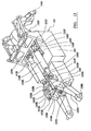
- Figs. 12 and 13 are perspective views from the front and rear respectively of the chassis and suspensions of a four-wheel motorcycle-type vehicle, incorporating suspensions of the kind shown in Figs. 10 and 11 , for the front and rear wheels. Parts corresponding to those shown in Figs. 10 and 11 are indicated by the same preference numerals increased by 100 and with the suffix F for the front suspension and R for the rear suspension.
- the chassis shown in Figs. 12 and 13 has a mainframe 100 defining a location 101 for a prime move such as an internal combustion engine and a housing 102 for a transmission which may include a mechanical gearbox or a generator.
- the rear, trailing suspension arms 106R are each independently pivoted at their front ends to the rear of the frame 100.
- the suspension arms 106F at the front of the vehicle are of an inverted U or J shape and are each independently pivoted to the front of the frame 100 again about a common transverse axis as leading suspension arms.
- Suspension locking brakes 121F and 121R enable the suspension arms 106F and 106R to be locked to each other and/or to the frame in an emergency.
- Each of the front swing arms 106F has a short lateral extension connected by the ball joint 132F to the connecting link 131F which is connected at its other end by the ball joint 133F to an arm of the beam 126F which is pivotally mounted on the cross-head 142F.
- the cross-head 142F is slidable along parallel guide rods 143F which have their ends secured in brackets 150F secured to the frame 100 at each end.
- One end of the front resilient suspension unit 135F is secured to the cross-head 142F while its other, rear end is connected by the ram 141F and a device to an upstanding lug 152F to a portion of the frame 100.
- Each of the rear swing arms 106R carries an upstanding lug 153R which are connected by the ball joints 132R, constant length links 131R and ball joints 133R to the opposite ends of the rear suspension beam 126R which is pivoted again about a vertical axis on the rear cross-head 142R.
- the guide rods 143R for the cross-hcad 142R are fixed at each end in brackets 150R.
- the rear end of the rear suspension unit 135R is secured to the cross-head 142R while the rear ram 141R interconnects the front of the rear unit 135R with an upstanding lug 152R on the frame 100.
- the two suspension units 135F and 135R are side by side and offset from the centre line of the vehicle to produce a compact arrangement with a low centre of gravity.
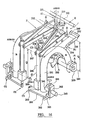
- the frame has an upstanding bridge portion extending over the front connecting links 131F to form a support for the steering linkage which is shown on an enlarged scale in Figs. 14 and 15 .
- an Ackermann-type linkage is located above an upper wishbone member 171 and a stub axle assembly 172 is formed integrally with a vertical strut 173.
- the swing arm 106F carries a bracket 160 on which the lower end of the stub axle assembly 172 is articulated by means of a ball joint 164.
- the centre of the ball joint 164 lies in the central plane of the tyre (not seen), thereby providing wheel centre steering.
- the strut 173 is offset at 174.
- the strut 173 carries an arm 175.
- the arm 175 is articulated to the leading end of the wishbone member 171 by means of a ball joint 176.
- a drag link 177 is articulated to the upper end of the strut 173 by means of a ball joint 178. At its rear end, the drag link 177 is articulated by a ball joint 179 to one arm of a bell-crank lever 180 which is pivotally mounted on the bridge at 180 and has its other arm 182 articulated at 183 to the outer end of a track rod 184. The inner end of each track rod 184 pivots at 185 to an arm 186 on the stem 187 of the handle bars 2 ( Fig. 1 ), (or a steering wheel) thereby forming an Ackermann steering linkage.
- the distance X 1 between the pivotal axis 149 of the front swing arms 106F and that of the ball joint 164 is equal to the distance between the axis 162 and the ball joint 176. Further, the distance X 2 between the ball joint 176 and the ball joint 164 is equal to the distance between the axis 162 and the axis 149. Accordingly, the axes represented by 162, 149, 164 and 176 form a first parallelogram. A second parallelogram (X 1 , X 4 ) is effectively formed by the axes of 176, 178, 179 and 162.
- the Ackermann-type steering developed by the members 184 and 182 is transmitted to the front road wheels by these two parallelogram linkages which also provide constant trail for the suspension irrespective of up and down movements of the wheel and without deflecting the handlebars.
- the arrangement is also suitable for a single front wheel vehicle.
- the inverted U or J shape of the front swing arms 106 permits the rear portions of the front wheels to turn without obstruction under the underside of the rear limb 107 of the swing arm.
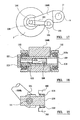
- each rear, trailing suspension arm 106R which may be an aluminium alloy forging, has a bore 108 in which a steel sleeve 109 is fixedly secured.
- the two ends of the sleeve 109 are supported in lugs 112 carried by the vehicle body by means of appropriate bearings 112a, which may for example be double row roller or ball bearings.
- bearings 112a which may for example be double row roller or ball bearings.
- Within the sleeve 109 is a shaft 111 supported in end caps 115 fixed in the internal bore of the sleeve 109 by screw threads.
- the shaft 111 projects from one of the end caps 115 to carry one element 121 such as the brake sector, of the suspension stabilising brake.
- the shaft 111 has projections 113 interposed with clearance between internal projections 114 on the interior of the bore.
- resilient buffer elements for example of rubber, are inserted in the spaces between the projections 113 and 114.
- the projections 113 and 114 are made sufficiently large to avoid any clearance and may in fact be replaced by a splined connection between the shaft 111 and the sleeve 109.
- Fig. 18 may be used between the balance beam and the cross-head. This situation may occur where a differential unit is required in the position shown for the brake 121R in Fig. 13 . Where zero suspension movement for b type situations and residual suspension movement for c type situations is required, an electrically-stiffened suspension damper would be used which is automatically activated when the suspension brake is engaged.
- the front suspension has a swing arm 231 for each front wheel.
- Each swing arm 231 is of inverted J shape having its shorter limb pivotally mounted on the frame F by the arrangement shown in Fig. 7 and connected, by the lost motion arrangement shown in Fig. 7 to a further brake sector 232.
- Approximately horizontal suspension struts 233 are articulated to the swing arms 231 at 234 at one end and to a beam 235 at the other end.
- the beam 235 is pivotally mounted on the frame in the manner of the beam 26 of the rear suspension but in this case the pivotal axis is approximately vertical.
- the brake discs 232 can be arrested by a brake caliper 237 secured to the frame.
- each swing arm 231 At the lower front end of each swing arm 231 is pivotally mounted a cross shaft 241 carrying at one end, a stub axle assembly 242 with an axle 243 for the front wheel (not shown).
- the stub axle assembly 242 can turn on the shaft 241 by means of a king pin 244.
- the shaft 241 extends inwardly of the vehicle beyond the inner face of the swing arm 231 and is secured in a block 245 at the lower end of a tubular strut 246. Near its upper end, the strut 246 is pivoted about a transverse axis 247 to the front end of a wishbone member 248, the rear end of which is pivotally mounted on a shaft 249 carried in lugs 250 secured to the frame F.
- the handlebars 202 are carried on an upwardly extending shaft 251 which is supported in a bearing assembly 252 secured to the frame F.
- a shaft 251 carries short lever arms 253.
- Upper steering rods 254 are articulated at one end 255 to the lever 253 and at their forward ends at 256 to crank levers 257 which are of the same effective length as the levers 253.
- crank levers 257 are mounted on the upper ends of steering shafts 258 extending downwards through the struts 246 to terminate in lower crank arms 259 to which are articulated at 260 lower steering rods 261 articulated at their other ends 262 to steering lever 263 secured to the stub axle assemblies 242.
- the distance between the axis of each shaft 241 and the pivotal axis 264 of the swing arm 231 is equal to the distance between the axis 247 and the axis of the shaft 249. Further, the distance between the axis of the shaft 249 and pivotal axis 264 of the swing arm is equal to the distance between the axis 247 and the axis of the shaft 241, thereby resulting in a parallelogram linkage maintaining the strut 46 parallel to a particular axis of the frame.
- Locating the suspension brakes on the pivotal axes of the swing arms reduces the unsprung weight and keeps the centre of gravity of the vehicle low.
- the links connecting the swing arms may be arranged to be in tension rather than compression, for example, by mounting the lugs 153 on the underside of their swing arms.
- Fig. 17 shows an arrangement for driving one of the rear wheels.
- the front portion of the rear trailing suspension arm 106 forms a mounting for a hydraulic or electric motor 192 which drives a toothed pulley 193.
- a further toothed pulley 194 mounted on the axle 108 at the rear end of the suspension arm 106 is secured to the rear wheel.
- a toothed belt 195 extends around the pulleys 193 and 194 so that the motor 192 drives the rear wheel.
- the pulleys 193 and 194 and belt 195 could of course be replaced by a convention chain and sprocket drive.
- the two motors 192 are mounted near the axis 7 and so do not greatly increase the unsprung mass of the rear suspension.
- the motors 192 if hydraulic are supplied by a common swash-plate pump, or if electric by a generator, driven by an internal combustion engine.
- the drive is shared between the two motors in such a manner that they form a differential drive.
- the effective gear ratio between the engine and the rear wheels can be varied by varying the angle of the pump swash-plate or generator output. This may be controlled automatically in response to the torque encountered by each wheel and the road speed. As a result of using this transmission or other automatic transmission, the need for a hand operated clutch control on the left-hand handle bar is avoided.
- This control may be replaced by a manual control for the stabilising brakes.
- This control may be similar to the brake lever 88 ( fig. 1 ) for controlling the front road wheel brakes.
- the rear wheels each incorporate an electric motor which is supplied by a common generator driven by the prime mover.
- the front wheels may instead, or additionally, incorporate electric motors supplied by the generator.
- a hydraulic suspension unit 301 is connected by a respective link 302 to the suspension swing arm 306 for the respective wheel.
- the hydraulic chambers of the two hydraulic suspension units 301 are connected together by a line 307 which is also connected to the hydraulic oil chamber of an oleo pneumatic accumulator 308 in which a body of compressed gas 309 pressurises a body of oil 310 and thereby the oil in the two suspension units 301.
- additional oil can be fed into the system through a line 311 supplied either directly from a system of the kind shown in Fig. 11 or by the use of a ram 312 to displace oil from a chamber 313.
- the vehicle's components are mounted as low as practically possible to give the vehicle a low centre of gravity, perhaps with the fuel tank between the back wheels, a useful space is created on top of the main components either side of the seat post. These spaces could have racks on them for tying down transported items or for permanent or removable containers. If removable, the containers could have their own wheels and extendable handle for easy transportation to and from the vehicle as shown in the following diagram.
- the seat post could be mounted to one side or from the front or back of the vehicle to give an interrupted load space.
- Figs. 21 and 22 are side views of a vehicle of the kind shown in Figs. 12 to 14 .
- the vehicle has a fuel tank 320 mounted between the rear, trailing suspensions arms 106R which, as shown here can be of curved shape.
- An upstanding post 321 extends upwards from the body structure 100 between the suspension units 135F and 135R ( Figs. 12 and 13 ) to carry a suitable seat or saddle 322.
- a low centre of gravity is achieved. This enables containers for goods such as those shown at 323 to be carried one between the post 321 and the handlebars 2 and the other behind the post 321 as shown in Fig. 21 .
- the containers 323 have a pair of small wheels 324 and a retractable handle 325.
- the stabilising brake arrangement shown in Fig. 7 may be used for each of the suspension arms.
- the stabilising brakes When the stabilising brakes are engaged, limited residual suspension movement remains available in response to both b and c type situations. If no residual resilient suspension is required in response to b type situations when the stabilising brakes are applied, the stabilising brakes would be arranged to act directly on the suspension arms without the interposition of any resilient elements. If residual resilience is required in such a case in response to c type situations, the brakes could be resiliently mounted to the vehicle.
- the vehicle described above can be ridden under normal conditions like a conventional motor bicycle as shown in figs. 2 and 3 .
- the maximum angle of tilt, however, allowed by the suspension need only be about 30° to accommodate cornering forces which would require a conventional two-wheel motorcycle to lean at an angle of 45°.
- the rider can engage the stabilising brakes to prevent further tilting of the vehicle (other than the relatively small residual angular movement where allowed by the lost-motion device such as shown in fig. 7 ).
- This control arrangement may be augmented by sensing means (for example an accelerometer arranged to detect abnormal lateral acceleration) for detecting incipient instability and reacting more quickly than the rider to apply the stabilising brakes. The rider then assumes manual control of the stabilising brakes and releases them when the dangerous condition has passed.
Landscapes
- Engineering & Computer Science (AREA)
- Mechanical Engineering (AREA)
- Chemical & Material Sciences (AREA)
- Combustion & Propulsion (AREA)
- Transportation (AREA)
- Axle Suspensions And Sidecars For Cycles (AREA)
- Vehicle Body Suspensions (AREA)
Applications Claiming Priority (2)
| Application Number | Priority Date | Filing Date | Title |
|---|---|---|---|
| GB0029136A GB0029136D0 (en) | 2000-11-29 | 2000-11-29 | Motorcycle-type vehicle |
| EP01998472A EP1339599B1 (fr) | 2000-11-29 | 2001-11-29 | Vehicule de type motocycle |
Related Parent Applications (1)
| Application Number | Title | Priority Date | Filing Date |
|---|---|---|---|
| EP01998472.3 Division | 2001-11-29 |
Publications (3)
| Publication Number | Publication Date |
|---|---|
| EP2196386A2 true EP2196386A2 (fr) | 2010-06-16 |
| EP2196386A3 EP2196386A3 (fr) | 2011-05-25 |
| EP2196386B1 EP2196386B1 (fr) | 2012-11-28 |
Family
ID=9904131
Family Applications (2)
| Application Number | Title | Priority Date | Filing Date |
|---|---|---|---|
| EP10003570A Expired - Lifetime EP2196386B1 (fr) | 2000-11-29 | 2001-11-29 | Véhicule de type motocyclette |
| EP01998472A Expired - Lifetime EP1339599B1 (fr) | 2000-11-29 | 2001-11-29 | Vehicule de type motocycle |
Family Applications After (1)
| Application Number | Title | Priority Date | Filing Date |
|---|---|---|---|
| EP01998472A Expired - Lifetime EP1339599B1 (fr) | 2000-11-29 | 2001-11-29 | Vehicule de type motocycle |
Country Status (5)
| Country | Link |
|---|---|
| EP (2) | EP2196386B1 (fr) |
| AU (1) | AU2002216195A1 (fr) |
| ES (2) | ES2397602T3 (fr) |
| GB (1) | GB0029136D0 (fr) |
| WO (1) | WO2002044008A2 (fr) |
Cited By (2)
| Publication number | Priority date | Publication date | Assignee | Title |
|---|---|---|---|---|
| EP2889210A1 (fr) * | 2013-12-27 | 2015-07-01 | Honda Motor Co., Ltd. | Système de commande de basculement d'un véhicule à bascule |
| WO2020012801A1 (fr) * | 2018-07-12 | 2020-01-16 | ソニー株式会社 | Véhicule |
Families Citing this family (39)
| Publication number | Priority date | Publication date | Assignee | Title |
|---|---|---|---|---|
| EP1362779B1 (fr) | 2002-05-17 | 2011-04-20 | The Four Wheeled Motorcycle Company Limited | Véhicule de type motocycle |
| DE60319307T2 (de) * | 2002-07-05 | 2008-06-12 | Honda Giken Kogyo K.K. | Dreirad mit Motor und Neigungsmechanismus |
| WO2004056645A1 (fr) | 2002-12-20 | 2004-07-08 | Pedersen Roald H | Vehicule presentant un chassis inclinable |
| ITMI20031108A1 (it) * | 2003-06-03 | 2004-12-04 | Piaggio & C Spa | Veicolo rollante a tre ruote con due ruote anteriori sterzanti |
| ITMI20040172A1 (it) | 2004-02-04 | 2004-05-04 | Piaggio & C Spa | Dispositivo di arresto corsa delle sospensioni di un veicolo |
| DE602006009391D1 (de) | 2006-07-26 | 2009-11-05 | Yamaha Motor Europ | Motorrad |
| EP2046589B1 (fr) | 2006-07-28 | 2010-04-28 | Marabese Design S.r.l. | Système pour ajuster l'assiette de motocycles comportant trois ou quatre roues |
| ITMI20062084A1 (it) * | 2006-10-30 | 2008-04-30 | Piaggio & C Spa | Veicolo rollante a tre ruote con due ruote anteriori sterzanti ed una ruota posteriore motrice |
| EP2099624A1 (fr) * | 2006-12-01 | 2009-09-16 | The Four Wheeled Motorcycle Company Limited | Système de suspension |
| GB2461844B (en) * | 2008-06-20 | 2011-04-06 | Gibbs Tech Ltd | A two wheeled amphibian with retractable wheels |
| ITMI20081453A1 (it) * | 2008-08-04 | 2010-02-04 | Marabese Design S R L | Sistema di pendolamento delle ruote ad ingombro trasversale ridotto per veicoli a tre o più ruote |
| JP5237783B2 (ja) * | 2008-12-19 | 2013-07-17 | ヤマハ発動機株式会社 | 鞍乗型車両 |
| GB0903753D0 (en) * | 2009-03-04 | 2009-04-15 | Four Wheeled Motorcycle Company | Engine configuration for mounting suspension arms |
| EP2628672B1 (fr) * | 2009-09-08 | 2017-04-19 | Ino8 Pty Ltd | Commande d'inclination pour véhicules inclinables |
| DE102009042662A1 (de) * | 2009-09-23 | 2011-03-24 | Bayerische Motoren Werke Aktiengesellschaft | Achsmodul für Pendelachse eines Kraftfahrzeugs |
| GB2475309A (en) * | 2009-11-16 | 2011-05-18 | Agco Sa | Vehicle axle mounting arrangement |
| BR112012011903A2 (pt) * | 2009-11-18 | 2019-09-24 | Actua S R L | veículo inclinável e seu sistema de controle |
| US9216763B2 (en) * | 2010-09-01 | 2015-12-22 | Timothy Huntzinger | Personal mobility device |
| ES2384347B1 (es) * | 2010-12-07 | 2013-05-16 | Stilz Automotive Galicia, S.L. | Sistema de suspension trasera para vehiculos de tres ruedas |
| GB201108598D0 (en) * | 2011-05-20 | 2011-07-06 | Shotter Nicholas R | Front suspension system |
| FR2995869B1 (fr) * | 2012-09-27 | 2015-07-31 | Venturi Automobiles | Véhicule inclinable. |
| FR2995868B1 (fr) * | 2012-09-27 | 2015-07-31 | Venturi Automobiles | Vehicule inclinable |
| CA2952358A1 (fr) | 2014-06-20 | 2015-12-23 | Quadro Vehicles Sa | Systeme de commande ameliore de l'assiette de vehicules ayant plus de deux roues |
| CA2953068A1 (fr) | 2014-07-04 | 2016-01-07 | Riccardo Marabese | Dispositif de freinage electronique du systeme d'inclinaison d'un vehicule avec trois roues a inclinaison ou davantage |
| CA3005807A1 (fr) | 2015-11-20 | 2017-05-26 | Yamaha Hatsudoki Kabushiki Kaisha | Vehicule a inclinaison |
| CA3005823A1 (fr) | 2015-11-20 | 2017-05-26 | Yamaha Hatsudoki Kabushiki Kaisha | Vehicule a inclinaison |
| CA3005803A1 (fr) | 2015-11-20 | 2017-05-26 | Yamaha Hatsudoki Kabushiki Kaisha | Vehicule inclinable |
| EP3363723B1 (fr) | 2015-11-20 | 2020-04-01 | Yamaha Hatsudoki Kabushiki Kaisha | Véhicule |
| WO2017090666A1 (fr) * | 2015-11-24 | 2017-06-01 | ヤマハ発動機株式会社 | Véhicule inclinable |
| IT201600071538A1 (it) | 2016-07-08 | 2018-01-08 | G P Di Ghezzi Giuseppe | Veicolo a tre o piu' ruote basculanti, con sospensione a vincolo reattivo. |
| JP6541273B2 (ja) | 2017-02-10 | 2019-07-10 | 本田技研工業株式会社 | 前二輪懸架装置 |
| FR3072330B1 (fr) * | 2017-10-13 | 2019-10-25 | Eccity Motocycles | Vehicule a train roulant ameliore |
| PT110397A (pt) * | 2017-11-07 | 2019-05-07 | Lilia Raquel Da Silva Conceicao | Dispositivo de roda dupla frontal para bicicleta e semelhante. |
| FR3074099B1 (fr) * | 2017-11-24 | 2019-10-18 | Psa Automobiles Sa | Dispositif de suspension hydropneumatique pour un vehicule automobile inclinable, a blocage du roulis a l’arret |
| NL2020889B1 (en) * | 2018-05-08 | 2019-05-22 | Royalty Bugaboo Gmbh | Improved tilting suspension for a vehicle |
| JP7182701B2 (ja) * | 2018-09-28 | 2022-12-02 | ピアッジオ エ チ.ソシエタ ペル アチオニ | 二重操舵棒を備えた二つの前輪を有する車両用の前輪部及び前記前輪部を備えた車両 |
| IT201800010942A1 (it) * | 2018-12-10 | 2020-06-10 | Piaggio & C Spa | Avantreno per veicolo a due ruote anteriori sterzanti e motoveicolo comprendente detto avantreno |
| IL278369B (en) * | 2020-10-28 | 2021-03-25 | Trollypack Ltd | A scooter with automatic tilting of the steering rod |
| CN115848548B (zh) * | 2022-11-17 | 2024-04-05 | 昆明理工大学 | 一种二分之一车的isd多层悬架支撑装置 |
Family Cites Families (9)
| Publication number | Priority date | Publication date | Assignee | Title |
|---|---|---|---|---|
| US4020914A (en) * | 1976-02-23 | 1977-05-03 | Wolfgang Trautwein | Stabilized three-wheeled vehicle |
| JPS60139583A (ja) * | 1983-12-26 | 1985-07-24 | 本田技研工業株式会社 | 自動二輪車のフロントリ−デイングア−ム構造 |
| US4828069A (en) * | 1986-02-18 | 1989-05-09 | Honda Giken Kogyo Kabushiki Kaisha | Motorcycle |
| US4756379A (en) | 1986-06-04 | 1988-07-12 | Honda Giken Kogyo Kabushiki Kaisha | Motorcycle |
| FR2609442B1 (fr) * | 1987-01-12 | 1990-12-21 | Elf France | Perfectionnements aux roues directrices de vehicules terrestres |
| DE29510091U1 (de) * | 1995-06-22 | 1995-10-12 | CARBIKE Leichtfahrzeuge GmbH & Co KG, 88131 Lindau | Lenkung für Muskelkraft-Elektro-Hybridfahrzeuge |
| US6263994B1 (en) * | 1997-10-03 | 2001-07-24 | Frederick G. Eitel | Advanced motorcycle chassis steering and suspension system |
| DE19823002A1 (de) | 1998-05-22 | 1999-11-25 | Jan Klindworth | Achsschenkellenkung für Krafträder |
| AT411166B (de) * | 2001-08-30 | 2003-10-27 | Hans Leeb Zweirad Handel Gmbh | Motorfahrzeug mit einem angetriebenen hinterrad und zwei gelenkten vorderrädern |
-
2000
- 2000-11-29 GB GB0029136A patent/GB0029136D0/en not_active Ceased
-
2001
- 2001-11-29 ES ES10003570T patent/ES2397602T3/es not_active Expired - Lifetime
- 2001-11-29 EP EP10003570A patent/EP2196386B1/fr not_active Expired - Lifetime
- 2001-11-29 EP EP01998472A patent/EP1339599B1/fr not_active Expired - Lifetime
- 2001-11-29 WO PCT/GB2001/005294 patent/WO2002044008A2/fr not_active Ceased
- 2001-11-29 AU AU2002216195A patent/AU2002216195A1/en not_active Abandoned
- 2001-11-29 ES ES01998472T patent/ES2388059T3/es not_active Expired - Lifetime
Non-Patent Citations (1)
| Title |
|---|
| None |
Cited By (3)
| Publication number | Priority date | Publication date | Assignee | Title |
|---|---|---|---|---|
| EP2889210A1 (fr) * | 2013-12-27 | 2015-07-01 | Honda Motor Co., Ltd. | Système de commande de basculement d'un véhicule à bascule |
| WO2020012801A1 (fr) * | 2018-07-12 | 2020-01-16 | ソニー株式会社 | Véhicule |
| US11970238B2 (en) | 2018-07-12 | 2024-04-30 | Sony Corporation | Vehicle |
Also Published As
| Publication number | Publication date |
|---|---|
| WO2002044008A2 (fr) | 2002-06-06 |
| ES2388059T3 (es) | 2012-10-08 |
| ES2397602T3 (es) | 2013-03-08 |
| EP2196386B1 (fr) | 2012-11-28 |
| EP1339599B1 (fr) | 2012-05-30 |
| EP1339599A2 (fr) | 2003-09-03 |
| WO2002044008A3 (fr) | 2002-09-12 |
| GB0029136D0 (en) | 2001-01-10 |
| EP2196386A3 (fr) | 2011-05-25 |
| AU2002216195A1 (en) | 2002-06-11 |
Similar Documents
| Publication | Publication Date | Title |
|---|---|---|
| EP2196386B1 (fr) | Véhicule de type motocyclette | |
| JP6538571B2 (ja) | 傾斜車両 | |
| US7669864B2 (en) | Laterally-leaning four wheeled vehicle | |
| US5957473A (en) | Rear suspension bicycle | |
| US9994277B2 (en) | Three-wheeled tilting vehicle | |
| US7850180B2 (en) | Hub assembly for a tilting vehicle suspension | |
| US5485893A (en) | Vehicle | |
| EP2199195A1 (fr) | Motocyclette | |
| EP1362779B1 (fr) | Véhicule de type motocycle | |
| JPH04500647A (ja) | 車輌用サスペンション装置 | |
| CN110997360B (zh) | 车辆的悬架组件 | |
| US4453616A (en) | Rear suspension system for a motor-tricycle | |
| US4984650A (en) | Motorcycle | |
| US4592441A (en) | Three-wheeled motor vehicle with pivotable frame | |
| US11772738B2 (en) | Rear wheel linkage system for a chain-wheeled vehicle | |
| EP3981679B1 (fr) | Système de ressort | |
| JPH0129194Y2 (fr) | ||
| EP1206360B1 (fr) | Vehicule avec dispositif de stabilisation destine au deplacement de composants structuraux | |
| WO2025016829A1 (fr) | Système de suspension inclinable et orientable à entraînement soutenu, en particulier pour un véhicule à trois ou à plusieurs roues | |
| EP4098531A1 (fr) | Véhicule | |
| WO2023238020A1 (fr) | Véhicule | |
| CN2133505Y (zh) | 三轮车的单转向轮的控制装置 | |
| GB2595506A (en) | Vehicle | |
| GB2624322A (en) | Vehicle |
Legal Events
| Date | Code | Title | Description |
|---|---|---|---|
| PUAI | Public reference made under article 153(3) epc to a published international application that has entered the european phase |
Free format text: ORIGINAL CODE: 0009012 |
|
| AC | Divisional application: reference to earlier application |
Ref document number: 1339599 Country of ref document: EP Kind code of ref document: P |
|
| AK | Designated contracting states |
Kind code of ref document: A2 Designated state(s): AT BE CH CY DE DK ES FI FR GB GR IE IT LI LU MC NL PT SE TR |
|
| PUAL | Search report despatched |
Free format text: ORIGINAL CODE: 0009013 |
|
| AK | Designated contracting states |
Kind code of ref document: A3 Designated state(s): AT BE CH CY DE DK ES FI FR GB GR IE IT LI LU MC NL PT SE TR |
|
| RIC1 | Information provided on ipc code assigned before grant |
Ipc: B60G 3/20 20060101ALI20110421BHEP Ipc: B62K 5/08 20060101ALI20110421BHEP Ipc: B62K 5/02 20060101ALI20110421BHEP Ipc: B62K 25/00 20060101ALI20110421BHEP Ipc: B62K 25/24 20060101AFI20100504BHEP |
|
| 17P | Request for examination filed |
Effective date: 20111102 |
|
| GRAP | Despatch of communication of intention to grant a patent |
Free format text: ORIGINAL CODE: EPIDOSNIGR1 |
|
| GRAS | Grant fee paid |
Free format text: ORIGINAL CODE: EPIDOSNIGR3 |
|
| GRAA | (expected) grant |
Free format text: ORIGINAL CODE: 0009210 |
|
| AC | Divisional application: reference to earlier application |
Ref document number: 1339599 Country of ref document: EP Kind code of ref document: P |
|
| AK | Designated contracting states |
Kind code of ref document: B1 Designated state(s): AT BE CH CY DE DK ES FI FR GB GR IE IT LI LU MC NL PT SE TR |
|
| REG | Reference to a national code |
Ref country code: GB Ref legal event code: FG4D |
|
| REG | Reference to a national code |
Ref country code: CH Ref legal event code: EP |
|
| REG | Reference to a national code |
Ref country code: AT Ref legal event code: REF Ref document number: 586011 Country of ref document: AT Kind code of ref document: T Effective date: 20121215 |
|
| REG | Reference to a national code |
Ref country code: IE Ref legal event code: FG4D |
|
| REG | Reference to a national code |
Ref country code: DE Ref legal event code: R096 Ref document number: 60147447 Country of ref document: DE Effective date: 20130117 |
|
| REG | Reference to a national code |
Ref country code: ES Ref legal event code: FG2A Ref document number: 2397602 Country of ref document: ES Kind code of ref document: T3 Effective date: 20130308 |
|
| REG | Reference to a national code |
Ref country code: AT Ref legal event code: MK05 Ref document number: 586011 Country of ref document: AT Kind code of ref document: T Effective date: 20121128 |
|
| REG | Reference to a national code |
Ref country code: NL Ref legal event code: VDEP Effective date: 20121128 |
|
| PG25 | Lapsed in a contracting state [announced via postgrant information from national office to epo] |
Ref country code: SE Free format text: LAPSE BECAUSE OF FAILURE TO SUBMIT A TRANSLATION OF THE DESCRIPTION OR TO PAY THE FEE WITHIN THE PRESCRIBED TIME-LIMIT Effective date: 20121128 Ref country code: FI Free format text: LAPSE BECAUSE OF FAILURE TO SUBMIT A TRANSLATION OF THE DESCRIPTION OR TO PAY THE FEE WITHIN THE PRESCRIBED TIME-LIMIT Effective date: 20121128 |
|
| PG25 | Lapsed in a contracting state [announced via postgrant information from national office to epo] |
Ref country code: PT Free format text: LAPSE BECAUSE OF FAILURE TO SUBMIT A TRANSLATION OF THE DESCRIPTION OR TO PAY THE FEE WITHIN THE PRESCRIBED TIME-LIMIT Effective date: 20130328 Ref country code: GR Free format text: LAPSE BECAUSE OF FAILURE TO SUBMIT A TRANSLATION OF THE DESCRIPTION OR TO PAY THE FEE WITHIN THE PRESCRIBED TIME-LIMIT Effective date: 20130301 Ref country code: BE Free format text: LAPSE BECAUSE OF FAILURE TO SUBMIT A TRANSLATION OF THE DESCRIPTION OR TO PAY THE FEE WITHIN THE PRESCRIBED TIME-LIMIT Effective date: 20121128 |
|
| PG25 | Lapsed in a contracting state [announced via postgrant information from national office to epo] |
Ref country code: AT Free format text: LAPSE BECAUSE OF FAILURE TO SUBMIT A TRANSLATION OF THE DESCRIPTION OR TO PAY THE FEE WITHIN THE PRESCRIBED TIME-LIMIT Effective date: 20121128 |
|
| REG | Reference to a national code |
Ref country code: CH Ref legal event code: PL |
|
| PG25 | Lapsed in a contracting state [announced via postgrant information from national office to epo] |
Ref country code: DK Free format text: LAPSE BECAUSE OF FAILURE TO SUBMIT A TRANSLATION OF THE DESCRIPTION OR TO PAY THE FEE WITHIN THE PRESCRIBED TIME-LIMIT Effective date: 20121128 Ref country code: CH Free format text: LAPSE BECAUSE OF NON-PAYMENT OF DUE FEES Effective date: 20121130 Ref country code: LI Free format text: LAPSE BECAUSE OF NON-PAYMENT OF DUE FEES Effective date: 20121130 |
|
| REG | Reference to a national code |
Ref country code: IE Ref legal event code: MM4A |
|
| PG25 | Lapsed in a contracting state [announced via postgrant information from national office to epo] |
Ref country code: NL Free format text: LAPSE BECAUSE OF FAILURE TO SUBMIT A TRANSLATION OF THE DESCRIPTION OR TO PAY THE FEE WITHIN THE PRESCRIBED TIME-LIMIT Effective date: 20121128 |
|
| PLBE | No opposition filed within time limit |
Free format text: ORIGINAL CODE: 0009261 |
|
| STAA | Information on the status of an ep patent application or granted ep patent |
Free format text: STATUS: NO OPPOSITION FILED WITHIN TIME LIMIT |
|
| PG25 | Lapsed in a contracting state [announced via postgrant information from national office to epo] |
Ref country code: IE Free format text: LAPSE BECAUSE OF NON-PAYMENT OF DUE FEES Effective date: 20121129 |
|
| 26N | No opposition filed |
Effective date: 20130829 |
|
| PG25 | Lapsed in a contracting state [announced via postgrant information from national office to epo] |
Ref country code: CY Free format text: LAPSE BECAUSE OF FAILURE TO SUBMIT A TRANSLATION OF THE DESCRIPTION OR TO PAY THE FEE WITHIN THE PRESCRIBED TIME-LIMIT Effective date: 20121128 |
|
| REG | Reference to a national code |
Ref country code: DE Ref legal event code: R097 Ref document number: 60147447 Country of ref document: DE Effective date: 20130829 |
|
| PG25 | Lapsed in a contracting state [announced via postgrant information from national office to epo] |
Ref country code: TR Free format text: LAPSE BECAUSE OF FAILURE TO SUBMIT A TRANSLATION OF THE DESCRIPTION OR TO PAY THE FEE WITHIN THE PRESCRIBED TIME-LIMIT Effective date: 20121128 Ref country code: MC Free format text: LAPSE BECAUSE OF NON-PAYMENT OF DUE FEES Effective date: 20121130 |
|
| PG25 | Lapsed in a contracting state [announced via postgrant information from national office to epo] |
Ref country code: LU Free format text: LAPSE BECAUSE OF NON-PAYMENT OF DUE FEES Effective date: 20121129 |
|
| PGFP | Annual fee paid to national office [announced via postgrant information from national office to epo] |
Ref country code: FR Payment date: 20141119 Year of fee payment: 14 Ref country code: ES Payment date: 20141119 Year of fee payment: 14 Ref country code: GB Payment date: 20141119 Year of fee payment: 14 Ref country code: DE Payment date: 20141119 Year of fee payment: 14 |
|
| PGFP | Annual fee paid to national office [announced via postgrant information from national office to epo] |
Ref country code: IT Payment date: 20141126 Year of fee payment: 14 |
|
| REG | Reference to a national code |
Ref country code: DE Ref legal event code: R119 Ref document number: 60147447 Country of ref document: DE |
|
| GBPC | Gb: european patent ceased through non-payment of renewal fee |
Effective date: 20151129 |
|
| PG25 | Lapsed in a contracting state [announced via postgrant information from national office to epo] |
Ref country code: IT Free format text: LAPSE BECAUSE OF NON-PAYMENT OF DUE FEES Effective date: 20151129 |
|
| REG | Reference to a national code |
Ref country code: FR Ref legal event code: ST Effective date: 20160729 |
|
| PG25 | Lapsed in a contracting state [announced via postgrant information from national office to epo] |
Ref country code: GB Free format text: LAPSE BECAUSE OF NON-PAYMENT OF DUE FEES Effective date: 20151129 Ref country code: DE Free format text: LAPSE BECAUSE OF NON-PAYMENT OF DUE FEES Effective date: 20160601 |
|
| PG25 | Lapsed in a contracting state [announced via postgrant information from national office to epo] |
Ref country code: FR Free format text: LAPSE BECAUSE OF NON-PAYMENT OF DUE FEES Effective date: 20151130 |
|
| PG25 | Lapsed in a contracting state [announced via postgrant information from national office to epo] |
Ref country code: ES Free format text: LAPSE BECAUSE OF NON-PAYMENT OF DUE FEES Effective date: 20151130 |
|
| REG | Reference to a national code |
Ref country code: ES Ref legal event code: FD2A Effective date: 20180710 |