EP2196649B1 - Kühlvorrichtung für fahrzeug - Google Patents
Kühlvorrichtung für fahrzeug Download PDFInfo
- Publication number
- EP2196649B1 EP2196649B1 EP08792783A EP08792783A EP2196649B1 EP 2196649 B1 EP2196649 B1 EP 2196649B1 EP 08792783 A EP08792783 A EP 08792783A EP 08792783 A EP08792783 A EP 08792783A EP 2196649 B1 EP2196649 B1 EP 2196649B1
- Authority
- EP
- European Patent Office
- Prior art keywords
- passage
- cooling medium
- thermostat
- temperature
- circulation
- Prior art date
- Legal status (The legal status is an assumption and is not a legal conclusion. Google has not performed a legal analysis and makes no representation as to the accuracy of the status listed.)
- Not-in-force
Links
- 238000001816 cooling Methods 0.000 title claims description 35
- 239000002826 coolant Substances 0.000 claims description 173
- 230000007423 decrease Effects 0.000 claims description 6
- 230000003247 decreasing effect Effects 0.000 claims description 4
- 230000004044 response Effects 0.000 claims description 4
- XLYOFNOQVPJJNP-UHFFFAOYSA-N water Substances O XLYOFNOQVPJJNP-UHFFFAOYSA-N 0.000 description 152
- 238000010438 heat treatment Methods 0.000 description 4
- 230000004048 modification Effects 0.000 description 4
- 238000012986 modification Methods 0.000 description 4
- 238000010792 warming Methods 0.000 description 4
- 238000010586 diagram Methods 0.000 description 3
- 239000003795 chemical substances by application Substances 0.000 description 2
- 239000007787 solid Substances 0.000 description 2
- 230000015572 biosynthetic process Effects 0.000 description 1
- 238000007664 blowing Methods 0.000 description 1
- 238000002485 combustion reaction Methods 0.000 description 1
- 230000008602 contraction Effects 0.000 description 1
- 238000005260 corrosion Methods 0.000 description 1
- 230000000881 depressing effect Effects 0.000 description 1
- 239000012530 fluid Substances 0.000 description 1
- 238000007710 freezing Methods 0.000 description 1
- 238000004519 manufacturing process Methods 0.000 description 1
- 239000000463 material Substances 0.000 description 1
- 239000000155 melt Substances 0.000 description 1
- 238000002844 melting Methods 0.000 description 1
- 230000008018 melting Effects 0.000 description 1
- 238000013021 overheating Methods 0.000 description 1
- 239000008188 pellet Substances 0.000 description 1
- 230000004043 responsiveness Effects 0.000 description 1
- 239000000126 substance Substances 0.000 description 1
Images




Classifications
-
- F—MECHANICAL ENGINEERING; LIGHTING; HEATING; WEAPONS; BLASTING
- F01—MACHINES OR ENGINES IN GENERAL; ENGINE PLANTS IN GENERAL; STEAM ENGINES
- F01P—COOLING OF MACHINES OR ENGINES IN GENERAL; COOLING OF INTERNAL-COMBUSTION ENGINES
- F01P3/00—Liquid cooling
- F01P3/20—Cooling circuits not specific to a single part of engine or machine
-
- F—MECHANICAL ENGINEERING; LIGHTING; HEATING; WEAPONS; BLASTING
- F01—MACHINES OR ENGINES IN GENERAL; ENGINE PLANTS IN GENERAL; STEAM ENGINES
- F01P—COOLING OF MACHINES OR ENGINES IN GENERAL; COOLING OF INTERNAL-COMBUSTION ENGINES
- F01P2060/00—Cooling circuits using auxiliaries
- F01P2060/08—Cabin heater
Definitions
- the present invention relates to a cooling device for a vehicle that maintains the temperature of the engine of the vehicle at an appropriate level by circulating cooling medium.
- Vehicles have a cooling device that suppresses overheating and overcooling of the engine so as to maintain the temperature of the engine at an appropriate level.
- a water cooling type cooling device which cools the engine by circulating coolant water in the interior of the engine, has a water jacket, that is, a coolant water passage extending in a cylinder block and a cylinder head of the engine.
- the coolant water is circulated through the water jacket by means of a water pump so as to absorb the heat of the engine.
- the coolant water which has been heated to a high temperature by the heat of the engine, is then sent to a radiator, which is a heat exchanger. The coolant water is thus cooled by the air blowing through the radiator and returned to the water jacket.
- the cooling device for a vehicle has a bypass passage that allows the coolant water to bypass the radiator when circulating. Accordingly, when the engine warms up, the cooling device quickly raises the temperature of the coolant water to the appropriate level by circulating the coolant water via the bypass passage.
- thermostat which is a temperature sensitive valve that operates in response to the temperature of the coolant water flowing into the valve.
- various types of thermostats have been proposed and used as described in, for example, Japanese Laid-Open Patent Publications No. 02-146219 , No. 08-319828 , No. 10-019160 and No. 2006-37889 .
- Typical conventional thermostats have the basic configuration described below. Specifically, a thermostat includes a valve body that is moved by thermal expansion and thermal contraction of a substance sealed in a thermo-element, which is a temperature sensitive portion.
- a wax pellet type thermostat for example, employs a bullet-like container in which wax is sealed as its temperature sensitive portion.
- the wax which is a solid under low temperatures, melts and expands under high temperatures, thus moving the valve body of the thermostat. This selectively opens and closes the valve in such a manner that the coolant water is circulated via the bypass passage when the temperature of the coolant water is low but through the radiator when the temperature of the coolant water is sufficiently high.
- the coolant water that has been heated by the engine is used by a heater that raises the temperature in the passenger compartment.
- the coolant water is sent also to a heater core, which is a heat exchanger, and used by the heater core to warm the air that is blown into the passenger compartment.
- a cooling device for a vehicle employing the water cooling which has been described above, has a plurality of passages in which the coolant water circulates. Since the coolant water passages have complicated structures, a large number of components and steps are necessary for formation of the passages. Accordingly, it has been demanded that the configuration of passages for the coolant water be simplified to save the manufacturing costs.
- An internal combustion engine including a cooling circuit is furthermore known from DE 19*9 56 893 A1 which is closest prior art for the subject invention.
- an outlet of the engine connects to a thermostatic valve inlet via an engine drainpipe.
- a first outlet for this thermostatic valve connects to a main heat exchanger inlet via a cooler feed pipe.
- a cooling device for a vehicle includes a first passage through which a cooling medium is circulated between the interior of an engine and a radiator, a second passage through which the cooling medium is circulated between the interior of the engine and a heater core, and a thermostat that operates in response to the temperature of the cooling medium.
- the thermostat permits circulation of the cooling medium in the first passage when the temperature of the cooling medium is high, and stops the circulation of the cooling medium in the first passage when the temperature of the cooling medium is low.
- the second passage functions as a bypass passage through which the cooling medium circulates bypassing the radiator when the temperature of the cooling medium is low.
- a cooling device for a vehicle uses, as cooling medium, water in which an anti-freezing agent and an anti-corrosion agent are mixed, or coolant water.
- the cooling device circulates the coolant water so as to maintain the temperature of the engine at an appropriate level.
- Fig. 1 schematically shows the configuration of coolant water passages formed in the cooling device for a vehicle according to the present embodiment.
- the cooling device mainly includes a first passage for circulating the coolant water between the interior of the engine and a radiator 13, and a second passage for circulating the coolant water between the interior of the engine and a heater core 15.
- An outlet port of a water pump 10, which is interlocked to the crankshaft of the engine, is connected to a water jacket formed in a cylinder block 11 of the engine.
- the water jacket in the cylinder block 11 is connected to a water jacket formed in a cylinder head 12 of the engine.
- the water jacket in the cylinder head 12 is branched, at a downstream position, into a radiator inlet passage 14 extending to the radiator 13 and a heater inlet passage 16 extending to the heater core 15.
- the coolant water flowing in the radiator inlet passage 14 passes through the radiator 13, which functions as a heat exchanger that cools the coolant water by air flows produced by the vehicle when the vehicle runs or those generated by a fan.
- the coolant water is then sent to a thermostat 18 via a radiator return passage 17.
- the coolant water flowing in the heater inlet passage 16 passes through the heater core 15, which functions as a heat exchanger that heats the air blown into the passenger compartment using the coolant water that has been heated by the engine.
- the coolant water then passes through a heater return passage 19 and flows into the thermostat 18.
- the thermostat 18 is a temperature sensitive operation type valve, which operates in response to the temperature of the coolant water that has entered the valve. After having been sent to the thermostat 18, the coolant water is returned to the water pump 10 via an inlet line 20.
- the cooling device has a main passage, through which the coolant water is circulated sequentially through the water pump 10, the cylinder block 11, the cylinder head 12, the radiator inlet passage 14, the radiator 13, the radiator return passage 17, the thermostat 18, the inlet line 20, and then back to the water pump 10.
- the cooling device has a heater/bypass passage, through which the coolant water is circulated sequentially through the water pump 10, the cylinder block 11, the cylinder head 12, the heater inlet passage 16, the heater core 15, the heater return passage 19, the thermostat 18, the inlet line 20, and then back to the water pump 10.
- the thermostat 18 operates in correspondence with the temperature of the coolant water flowing into the thermostat 18. Specifically, when the temperature of the coolant water is low, such as when the engine is warming up, the thermostat 18 stops circulation of the coolant water through the main passage. When the temperature of the coolant water is high, such as after the engine warm-up has been completed, the thermostat 18 permits the circulation of the coolant water through the main passage. On the other hand, the thermostat 18 constantly permits circulation of the coolant water through the heater/bypass passage regardless of the temperature of the coolant water.
- the thermostat 18 limits the circulation of the coolant water through the heater/bypass passage, that is, increases the flow resistance to the coolant water circulating through the heater/bypass passage, compared to when the temperature of the coolant water is low.
- Such configuration of the thermostat 18 will be described below.
- Fig. 2A illustrates the circulation of the coolant water when the engine is warming up, which is when the temperature of the coolant water is low.
- Fig. 2B illustrates the circulation of the coolant water after the engine warm-up has been completed, that is, when the temperature of the coolant water is high.
- the thermostat 18 stops the circulation of the coolant water through the main passage passing through the radiator 13 when the temperature of the coolant water is low. Accordingly, as illustrated in Fig. 2A , all the coolant water is circulated through the heater/bypass passage.
- the thermostat 18 permits the circulation of the coolant water through the main passage passing through the radiator 13.
- the circulation of the coolant water through the heater/bypass passage passing through the heater core 15 is constantly permitted regardless of the temperature of the coolant water. Accordingly, in this state, the coolant water flows through both of the main passage and the heater/bypass passage as illustrated in Fig. 2B .
- the thermostat 18 limits the circulation of the coolant water through the heater/bypass passage, that is, increases the flow resistance to the coolant water circulating through the heater/bypass passage, compared to when the temperature of the coolant water is low.
- the thermostat 18 is configured in such a manner as to prevent the amount of the coolant water circulated through the heater/bypass passage from becoming less than the amount necessary for ensuring passenger compartment heating performance (heating performance required for the heater core 15).
- Fig. 3A shows a lateral cross-sectional configuration of the thermostat 18 at the time when the thermostat 18 is in a valve closed state, which is when the thermostat 18 stops the circulation of the coolant water through the main passage.
- Fig. 13B shows the lateral cross-sectional configuration of the thermostat 18 at the time when the thermostat 18 is in a valve open state, which is when the thermostat 18 permits the circulation of the coolant water through the main passage.
- the thermostat 18 is mounted in a thermostat housing 21 formed in a portion at which the radiator return passage 17, the heater return passage 19, and the inlet line 20 converge.
- the thermostat housing 21 has a cylindrical shape having an opening formed in a top surface.
- a dome-like joint portion 17a, which joins the radiator return passage 17 with the thermostat housing 21, is attached to an upper portion of the thermostat housing 21 in such a manner as to cover the opening of the thermostat housing 21.
- An opening communicating with the heater return passage 19 is formed in an inner bottom surface of the thermostat housing 21.
- An opening communicating with the inlet line 20 is formed in a side surface of the thermostat housing 21.
- the thermostat 18 also has a body frame 22, which is fixedly arranged between the thermostat housing 21 and the joint portion 17a.
- the body frame 22 has a water port 23, which is formed in a side surface of an upper portion of the body frame 22.
- An annular valve seat 24, which has an opening at the center, is integrally fixed to the body frame 22.
- a valve shaft 27 is fixed to an upper portion of the body frame 22.
- the valve shaft 27 supports a temperature sensitive portion of the thermostat 18, which is a thermo-element 28, in a manner movable in an up-and-down direction along the valve shaft 27.
- the thermo-element 28 includes a sleeve and a bullet-like casing both formed of flexible material, which are engaged with the valve shaft 27.
- a sealed space is formed between the sleeve and the casing and filled with wax.
- a valve body 32 which can be seated on the valve seat 24 to close the opening of the valve seat 24, is integrally fixed to an upper portion of the thermo-element 28.
- a spring 33 is arranged between the valve body 32 and the spring seat 26 in a compressed state. The spring 33 urges the thermo-element 28 and the valve body 32 upward, that is, in the direction in which the valve body 32 is moved to be seated on the valve seat 24.
- a guide member 34 which is substantially shaped as a circular tube, is fixed to a lower portion of the thermostat housing 21 and arranged around the circumference of the thermo-element 28.
- a spring 36 which is a spring other than the spring 33, is arranged, in a compressed state between a flange 35, which is formed at the lower end of the guide member 34, and the spring seat 26. The spring 36 presses the guide member 34 against the inner bottom surface of the thermostat housing 21 at the circumference of the opening communicating with the heater return passage 19. The coolant water that flows into the thermostat housing 21 via the heater return passage 19 is entirely sent through the interior of the guide member 34 and reaches the space around the thermo-element 28.
- the guide member 34 has a stepped portion 37, which is formed at the inner circumference of the guide member 34.
- the inner diameter of the portion of the guide member 34 below the stepped portion 37 is smaller than the inner diameter of the portion of the guide member 34 above the stepped portion 37.
- the wax sealed in the thermo-element 28 is maintained in a solid state.
- the valve body 32 is urged by the spring 33 to be seated on the valve seat 24, as illustrated in Fig. 3A . This causes the valve body 32 to close the opening of the valve seat 24, thus stopping the flow of the coolant water from the radiator return passage 17 to the inlet line 20 and consequently the circulation of the coolant water through the main passage passing through the radiator 13.
- thermo-element 28 is located above the stepped portion 37 of the guide member 34.
- the clearance between the outer circumference of the thermo-element 28 and the inner circumference of the guide member 34 forms a variable passage.
- thermo-element 28 When the temperature of the coolant water flowing from the heater return passage 19 is high, the heat of the coolant water heats the wax in the thermo-element 28, thus melting and expanding the wax. As illustrated in Fig. 3B , the expanded wax causes the sleeve of the thermo-element 28 to press the valve shaft 27 upward, thus depressing the thermo-element 28 together with the valve body 32. This separates the valve body 32 from the valve seat 24 and permits the flow of the coolant water from the radiator return passage 17 to the inlet line 20 via the opening of the valve seat 24 and consequently the circulation of the coolant water through the main passage passing through the radiator 13. At this time, a portion of the thermo-element 28 is moved to a position below the stepped portion 37 of the guide member 34.
- Fig. 4A shows the cross-sectional configuration taken along line 4A-4A of Fig. 3A , which is the cross-sectional configuration of the portion corresponding to the minimum cross-sectional area of the variable passage, which is formed in the clearance between the thermo-element 28 and the guide member 34, at the time when the thermostat 18 is in the valve closed state.
- the thermo-element 28 is located in the portion of the guide member 34 above the stepped portion 37, that is, the portion of the guide member 34 with the greater inner diameter. Accordingly, the minimum cross-sectional area of the variable passage is relatively great.
- Fig. 4B shows the cross-sectional configuration taken along line 4B-4B of Fig.
- thermo-element 28 is located in the portion of the guide member 34 below the stepped portion 37, that is, the portion of the guide member 34 with a smaller inner diameter. Accordingly, the minimum cross-sectional area of the variable passage is small, compared to when the thermostat 18 is in the valve closed state.
- the minimum cross-sectional area of the variable passage which is formed in the clearance between the thermo-element 28 and the guide member 34, is smaller when the thermostat 18 is in the valve open state than when the thermostat 18 is in the valve closed state. Accordingly, when the temperature of the coolant water is high, the thermostat 18 functions to limit the circulation of the coolant water through the heater/bypass passage, that is, to increase the flow resistance to the coolant water circulating through the heater/bypass passage, compared to when the temperature of the coolant water is low.
- the portion of the guide member 34 below the stepped portion 37 functions as a restricting portion.
- the restricting portion decreases the minimum cross-sectional area of the variable passage when the valve body 32 permits the circulation of the coolant water through the main passage through the radiator 13, compared to when the valve body 32 stops the circulation of the coolant water through the main passage.
- the thermostat 18 is configured in such a manner that, even when the valve body 32 permits the circulation of the coolant water through the main passage, the minimum cross-sectional area of the variable passage becomes greater than or equal to the cross-sectional area that allows the heater/bypass passage to ensure the flow amount necessary for the passenger compartment heating performance (the heating performance required for the heater core 15).
- the stepped portion 37 formed in the inner circumferential surface of the guide member 34 decreases the minimum cross-sectional area of the variable passage, which is formed between the guide member 34 and the thermo-element 28, when the thermostat 18 is in the valve closed state, compared to when the thermostat 18 is in the valve open state.
- the inner circumference of the guide member 34 may be configured in manners different from the manner employed in the embodiment, as long as the minimum cross-sectional area of the variable passage is decreased when the thermostat 18 is in the valve closed state compared to when the thermostat 18 is in the valve open state.
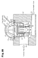
- a plurality of projections 41 which extend in an up-and-down direction of the guide member 40, are formed in a lower portion of a guide member 40.
- the thermo-element 28 is arranged in the lower portion of the guide member 40 only when the thermostat 18 is in the valve closed state. Also in this case, the circulation of the coolant water through the heater/bypass passage is limited when the thermostat 18 is in the valve open state compared to when the thermostat 18 is in the valve closed state.
- the portion from which the projections 41 are projected corresponds to the aforementioned restricting portion.
- the minimum cross-sectional area of the variable passage may be decreased by a projection projected from the outer circumference of the thermo-element 28.
- a guide member 42 has a uniform inner diameter from the upper end to the lower end of the guide member 42.
- a stepped portion 44 is formed in the outer circumferential surface of a thermo-element 43.
- the outer diameter of the portion of the thermo-element 43 above the stepped portion 44 is greater than the outer diameter of the portion of the thermo-element 43 below the stepped portion 44.
- the portion of the thermo-element 43 above the stepped portion 44 is located inside the guide member 42 only when the thermostat is in a valve open state.
- the minimum cross-sectional area of the variable passage is decreased when the thermostat is in the valve open state.
- the portion of the thermo-element 43 above the stepped portion 44 corresponds to the aforementioned restricting portion.
- the above-described embodiment employs the thermostat having the guide member that is arranged around the outer circumference of the thermo-element and guides the coolant water that has been sent from the heater return passage 19 to the space around the thermo-element.
- the present invention may be carried out using a thermostat without the aforementioned guide member.
- a thermostat configured to limit the circulation of the coolant water through the heater/bypass passage when the temperature of the coolant water is high compared to when the temperature of the coolant water is low.
- the thermostat is configured to stop the circulation of the coolant water through the heater/bypass passage after completion of engine warm-up, the heater is maintained operable as long as the circulation of the coolant water through the heater/bypass passage can be resumed when necessary.
- a thermostat operating without limiting the circulation of the coolant water may be employed.
- the configuration of the coolant water passages of the cooling device according to the above-described embodiment may be modified as needed. As long as a heater passage through which coolant water is circulated between the interior of the engine and the heater core functions also as a bypass passage that allows the coolant water to bypass the radiator while circulating, it is unnecessary to provide an additional bypass passage. This simplifies the configuration of the coolant water passages.
- the present invention is used in the cooling device that maintains the temperature of the engine at an appropriate level by circulating the coolant water.
- the invention may also be employed in a cooling device using fluid other than the coolant water as circulating cooling medium.
Landscapes
- Engineering & Computer Science (AREA)
- Chemical & Material Sciences (AREA)
- Combustion & Propulsion (AREA)
- Mechanical Engineering (AREA)
- General Engineering & Computer Science (AREA)
- Temperature-Responsive Valves (AREA)
- Heat-Exchange Devices With Radiators And Conduit Assemblies (AREA)
Claims (2)
- Kühlvorrichtung für ein Fahrzeug, aufweisend:eine erste Leitung (10, 11, 12, 13, 14, 17, 18, 20), durch die ein Kühlmedium zwischen dem Inneren eines Motors (11, 12) und einem Kühler (13) zirkuliert wird;eine zweite Leitung (10, 11, 12, 15, 16, 18, 19, 20), durch die das Kühlmedium zwischen dem Inneren des Motors (11, 12) und einem Heizungskern (15) zirkuliert wird; undeinen Thermostat (18), der in Reaktion auf die Temperatur des Kühlmedium arbeitet, wobei der Thermostat (18) eine Zirkulation des Kühlmediums in der ersten Leitung (10, 11, 12, 13, 14, 17, 18, 20) zulässt, wenn die Temperatur des Kühlmediums hoch ist, und die Zirkulation des Kühlmediums in der ersten Leitung (10, 11, 12, 13, 14, 17, 18, 20) stoppt, wenn die Temperatur des Kühlmediums niedrig ist,wobeidie zweite Leitung (10, 11, 12, 15, 16, 18, 19, 20) als eine Umgehungsleitung funktioniert, durch die das Kühlmedium den Kühler (13) umgehend zirkuliert, wenn die Temperatur des Kühlmediums niedrig ist;der Thermostat (18) so konfiguriert ist, dass er eine Zirkulation des Kühlmediums durch die zweite Leitung (10, 11, 12, 15, 16, 18, 19, 20) ungeachtet der Temperatur des Kühlmediums stets zulässt; und dassder Thermostat (18) ferner so konfiguriert ist, dass er die Zirkulation des Kühlmediums durch die zweite Leitung (10, 11, 12, 15, 16, 18, 19, 20) begrenzt, indem der Strömungswiderstand auf das durch die zweite Leitung (10, 11, 12, 15, 16, 18, 19, 20) zirkulierende Kühlmedium erhöht wird, wenn die Temperatur des Kühlmediums hoch ist, im Vergleich dazu, wenn die Temperatur des Kühlmediums niedrig ist,wobei der Themostat (18) aufweist:einen temperaturempfindlichen Bereich (28);einen Ventilkörper (32), der entsprechend der Temperatur des Kühlmediums, das den temperaturempfindlichen Bereich (28) umströmt, derart bewegt wird, dass die Zirkulation des Kühlmediums durch die erste Leitung (10, 11, 12, 13, 14, 17, 18, 20) selektiv zugelassen und gestoppt wird; undein rohrförmiges Führungselement (34, 40), das den äußeren Umfang des temperaturempfindlichen Bereichs (28) bedeckt und das Kühlmedium führt, das in den Thermostat (18) über die zweite Leitung (10, 11, 12, 15, 16, 18, 19, 20) zu einem Raum um den temperaturempfindlichen Bereich (28) geströmt ist;wobei ein Zwischenraum zwischen dem temperaturempfindlichen Bereich (28) und dem Führungselement eine variable Leitung ausbildet;wobei der Thermostat (18) so konfiguriert ist, dass er durch einen Begrenzungsbereich, der die minimale Querschnittsfläche der variablen Leitung verringert, wenn der Ventilkörper (32) die Zirkulation des Kühlmediums durch die erste Leitung (10, 11, 12, 13, 14, 17, 18, 20) zulässt, im Vergleich zu der minimalen Querschnittsfläche der variablen Leitung zu dem Zeitpunkt, wenn der Ventilkörper (32) die Zirkulation des Kühlmediums durch die erste Leitung (10, 11, 12, 13, 14, 17, 18, 20) stoppt, eine minimale Querschnittsfläche der variablen Leitung verringert, wenn der Ventilkörper (32) die Zirkulation des Kühlmediums durch die erste Leitung (10, 11, 12, 13, 14, 17, 18, 20) zulässt, im Vergleich zu der minimalen Querschnittsfläche der variablen Leitung zu dem Zeitpunkt, wenn der Ventilkörper (32) die Zirkulation des Kühlmediums durch die erste Leitung (10, 11, 12, 13, 14, 17, 18, 20) stoppt,dadurch gekennzeichnet, dass das rohrförmige Führungselement (34, 40) eine Mehrzahl von Vorsprüngen (41) aufweist, die sich in einer Aufwärts-AbwärtsRichtung des Führungselements (34, 40) erstrecken und die in einem Bereich des Führungselements (34, 40) ausgebildet sind, wo der temperaturempfindliche Bereich (28) angeordnet ist, wenn der Ventilkörper die Zirkulation des Kühlmediums durch die erste Leitung (10, 11, 12, 13, 14, 17, 18, 20) stoppt, wobei die Vorsprünge (41) als der Begrenzungsbereich des Thermostats (18) zum Verringern der minimalen Querschnittsfläche der variablen Leitung dienen, wenn der Ventilkörper (32) die Zirkulation des Kühlmediums zulässt.
- Kühlvorrichtung nach Anspruch 1, wobei,
wenn die Temperatur des Kühlmediums niedrig ist, das Kühlmedium durch die zweite Leitung (10, 11, 12, 15, 16, 18, 19, 20) in einer Menge zirkuliert wird, die der Gesamtmenge des Kühlmedium entspricht, das durch die erste und die zweite Leitung (10, 11, 12, 15, 16, 18, 19, 20) zu dem Zeitpunkt zirkuliert wird, wenn die Temperatur des Kühlmediums hoch ist.
Applications Claiming Priority (2)
| Application Number | Priority Date | Filing Date | Title |
|---|---|---|---|
| JP2007221510A JP4412368B2 (ja) | 2007-08-28 | 2007-08-28 | 車両の冷却装置 |
| PCT/JP2008/065273 WO2009028539A1 (ja) | 2007-08-28 | 2008-08-27 | 車両の冷却装置 |
Publications (3)
| Publication Number | Publication Date |
|---|---|
| EP2196649A1 EP2196649A1 (de) | 2010-06-16 |
| EP2196649A4 EP2196649A4 (de) | 2010-11-03 |
| EP2196649B1 true EP2196649B1 (de) | 2012-10-31 |
Family
ID=40387257
Family Applications (1)
| Application Number | Title | Priority Date | Filing Date |
|---|---|---|---|
| EP08792783A Not-in-force EP2196649B1 (de) | 2007-08-28 | 2008-08-27 | Kühlvorrichtung für fahrzeug |
Country Status (5)
| Country | Link |
|---|---|
| US (1) | US8534569B2 (de) |
| EP (1) | EP2196649B1 (de) |
| JP (1) | JP4412368B2 (de) |
| KR (1) | KR101018538B1 (de) |
| WO (1) | WO2009028539A1 (de) |
Families Citing this family (11)
| Publication number | Priority date | Publication date | Assignee | Title |
|---|---|---|---|---|
| DE102009020186B4 (de) * | 2009-05-06 | 2011-07-14 | Audi Ag, 85057 | Ausfallsicherer Drehsteller für einen Kühlmittelkreislauf |
| JP5201418B2 (ja) * | 2009-11-10 | 2013-06-05 | アイシン精機株式会社 | 内燃機関冷却システム及び内燃機関冷却システムにおける故障判定方法 |
| JP4649535B1 (ja) * | 2010-03-29 | 2011-03-09 | 富士精工株式会社 | サーモスタット装置 |
| JP5316819B2 (ja) * | 2010-12-13 | 2013-10-16 | 三菱自動車工業株式会社 | 車両用暖房装置 |
| JP6036022B2 (ja) * | 2012-08-31 | 2016-11-30 | いすゞ自動車株式会社 | サーモスタット |
| JP2015086974A (ja) * | 2013-10-31 | 2015-05-07 | ヤマハ発動機株式会社 | サーモスタット、水冷装置、水冷エンジンおよび船外機 |
| JP6287625B2 (ja) * | 2014-06-25 | 2018-03-07 | アイシン精機株式会社 | 内燃機関の冷却システム |
| USD743096S1 (en) | 2015-07-22 | 2015-11-10 | Luminara Worldwide, Llc | Electric, taper candle |
| JP6572879B2 (ja) * | 2016-12-26 | 2019-09-11 | トヨタ自動車株式会社 | 内燃機関の冷却装置 |
| US11378340B2 (en) * | 2018-06-21 | 2022-07-05 | The Boeing Company | Heat transfer devices and methods of cooling heat sources |
| JP7332643B2 (ja) * | 2021-02-17 | 2023-08-23 | 日本サーモスタット株式会社 | サーモスタット装置 |
Family Cites Families (13)
| Publication number | Priority date | Publication date | Assignee | Title |
|---|---|---|---|---|
| JPS61175534A (ja) | 1985-01-31 | 1986-08-07 | Yokogawa Electric Corp | 放射率測定装置 |
| JPS61175534U (de) * | 1985-04-22 | 1986-11-01 | ||
| US4883225A (en) | 1988-03-18 | 1989-11-28 | S.T.C., Inc. | Fail-safe thermostat for vehicular cooling systems |
| JPH0343529U (de) | 1989-09-08 | 1991-04-24 | ||
| US5184773A (en) | 1992-06-24 | 1993-02-09 | Siemens Automotive Limited | Pressure regulating heater control valve |
| JP3208283B2 (ja) | 1995-05-24 | 2001-09-10 | ダイハツ工業株式会社 | シリンダヘッドの冷却水通路構造 |
| JP2786172B2 (ja) | 1996-07-03 | 1998-08-13 | 富士トムソン株式会社 | 自動車エンジン冷媒循環回路制御用熱応動弁 |
| FR2796987B1 (fr) | 1999-07-30 | 2002-09-20 | Valeo Thermique Moteur Sa | Dispositif de regulation du refroidissement d'un moteur thermique de vehicule automobile |
| DE19956893A1 (de) * | 1999-11-26 | 2001-05-31 | Daimler Chrysler Ag | Kühlkreis für einen Verbrennungsmotor |
| US6460492B1 (en) * | 2001-05-24 | 2002-10-08 | Daimlerchrysler Corporation | Cooling system for an internal combustion engine |
| JP4400909B2 (ja) | 2003-04-04 | 2010-01-20 | 日本サーモスタット株式会社 | サーモスタット装置 |
| JP2006037889A (ja) | 2004-07-29 | 2006-02-09 | Nissan Motor Co Ltd | 内燃機関の冷却水経路の合流構造 |
| KR100755264B1 (ko) * | 2006-03-17 | 2007-09-04 | 고려전자주식회사 | 서머스탯장치 |
-
2007
- 2007-08-28 JP JP2007221510A patent/JP4412368B2/ja not_active Expired - Fee Related
-
2008
- 2008-08-27 WO PCT/JP2008/065273 patent/WO2009028539A1/ja not_active Ceased
- 2008-08-27 KR KR1020107006079A patent/KR101018538B1/ko not_active Expired - Fee Related
- 2008-08-27 US US12/674,025 patent/US8534569B2/en not_active Expired - Fee Related
- 2008-08-27 EP EP08792783A patent/EP2196649B1/de not_active Not-in-force
Also Published As
| Publication number | Publication date |
|---|---|
| US20110297365A1 (en) | 2011-12-08 |
| WO2009028539A1 (ja) | 2009-03-05 |
| EP2196649A4 (de) | 2010-11-03 |
| EP2196649A1 (de) | 2010-06-16 |
| KR101018538B1 (ko) | 2011-03-03 |
| US8534569B2 (en) | 2013-09-17 |
| JP4412368B2 (ja) | 2010-02-10 |
| KR20100043107A (ko) | 2010-04-27 |
| JP2009052506A (ja) | 2009-03-12 |
Similar Documents
| Publication | Publication Date | Title |
|---|---|---|
| EP2196649B1 (de) | Kühlvorrichtung für fahrzeug | |
| JP2001317355A (ja) | サーモスタット装置 | |
| JP4498636B2 (ja) | サーモスタット装置 | |
| JP2008138673A (ja) | エンジン冷却システム用のサーモスタット組立体 | |
| US5970927A (en) | Apparatus for circulating cooling water for internal combustion engine | |
| CN108361100A (zh) | 用于内燃机的冷却系统和恒温器装置 | |
| JP2009097352A (ja) | エンジンの冷却装置 | |
| US6929189B2 (en) | Thermostat device and temperature control method and system for engine coolant | |
| JP2012117485A (ja) | 内燃機関の冷却装置 | |
| US6460492B1 (en) | Cooling system for an internal combustion engine | |
| EP1537307B1 (de) | Motorkühlsysteme | |
| JP2010121455A (ja) | 熱応動弁装置 | |
| JP5517814B2 (ja) | エンジン冷却系システム | |
| JP2011069260A (ja) | サーモスタット及び同サーモスタットを備えるエンジンの冷却装置 | |
| JP2016138513A (ja) | エンジン | |
| JP4853450B2 (ja) | エンジンの冷却装置 | |
| JP2012197730A (ja) | エンジン | |
| CN209687589U (zh) | 一种用于车辆的发动机冷却系统及车辆 | |
| JP2012197729A (ja) | エンジン | |
| JP2007085457A (ja) | トランスミッションのオイル温度調整装置 | |
| JP2017008753A (ja) | 車両用内燃機関の冷却水制御装置及びこれに使用するサーモ弁装置 | |
| JP2012184672A (ja) | 内燃機関の冷却装置 | |
| JP4417644B2 (ja) | 車両冷却装置 | |
| JP2005214075A (ja) | 内燃機関の冷却装置 | |
| JP5935476B2 (ja) | エンジンの冷却装置 |
Legal Events
| Date | Code | Title | Description |
|---|---|---|---|
| PUAI | Public reference made under article 153(3) epc to a published international application that has entered the european phase |
Free format text: ORIGINAL CODE: 0009012 |
|
| 17P | Request for examination filed |
Effective date: 20100329 |
|
| AK | Designated contracting states |
Kind code of ref document: A1 Designated state(s): AT BE BG CH CY CZ DE DK EE ES FI FR GB GR HR HU IE IS IT LI LT LU LV MC MT NL NO PL PT RO SE SI SK TR |
|
| AX | Request for extension of the european patent |
Extension state: AL BA MK RS |
|
| A4 | Supplementary search report drawn up and despatched |
Effective date: 20101006 |
|
| DAX | Request for extension of the european patent (deleted) | ||
| 17Q | First examination report despatched |
Effective date: 20110512 |
|
| GRAP | Despatch of communication of intention to grant a patent |
Free format text: ORIGINAL CODE: EPIDOSNIGR1 |
|
| GRAS | Grant fee paid |
Free format text: ORIGINAL CODE: EPIDOSNIGR3 |
|
| GRAA | (expected) grant |
Free format text: ORIGINAL CODE: 0009210 |
|
| AK | Designated contracting states |
Kind code of ref document: B1 Designated state(s): AT BE BG CH CY CZ DE DK EE ES FI FR GB GR HR HU IE IS IT LI LT LU LV MC MT NL NO PL PT RO SE SI SK TR |
|
| REG | Reference to a national code |
Ref country code: GB Ref legal event code: FG4D Ref country code: CH Ref legal event code: EP |
|
| REG | Reference to a national code |
Ref country code: AT Ref legal event code: REF Ref document number: 582143 Country of ref document: AT Kind code of ref document: T Effective date: 20121115 |
|
| REG | Reference to a national code |
Ref country code: IE Ref legal event code: FG4D |
|
| REG | Reference to a national code |
Ref country code: DE Ref legal event code: R096 Ref document number: 602008019837 Country of ref document: DE Effective date: 20121227 |
|
| RAP2 | Party data changed (patent owner data changed or rights of a patent transferred) |
Owner name: TOYOTA JIDOSHA KABUSHIKI KAISHA |
|
| REG | Reference to a national code |
Ref country code: AT Ref legal event code: MK05 Ref document number: 582143 Country of ref document: AT Kind code of ref document: T Effective date: 20121031 |
|
| REG | Reference to a national code |
Ref country code: LT Ref legal event code: MG4D |
|
| REG | Reference to a national code |
Ref country code: NL Ref legal event code: VDEP Effective date: 20121031 |
|
| PG25 | Lapsed in a contracting state [announced via postgrant information from national office to epo] |
Ref country code: HR Free format text: LAPSE BECAUSE OF FAILURE TO SUBMIT A TRANSLATION OF THE DESCRIPTION OR TO PAY THE FEE WITHIN THE PRESCRIBED TIME-LIMIT Effective date: 20121031 Ref country code: ES Free format text: LAPSE BECAUSE OF FAILURE TO SUBMIT A TRANSLATION OF THE DESCRIPTION OR TO PAY THE FEE WITHIN THE PRESCRIBED TIME-LIMIT Effective date: 20130211 Ref country code: NL Free format text: LAPSE BECAUSE OF FAILURE TO SUBMIT A TRANSLATION OF THE DESCRIPTION OR TO PAY THE FEE WITHIN THE PRESCRIBED TIME-LIMIT Effective date: 20121031 Ref country code: IS Free format text: LAPSE BECAUSE OF FAILURE TO SUBMIT A TRANSLATION OF THE DESCRIPTION OR TO PAY THE FEE WITHIN THE PRESCRIBED TIME-LIMIT Effective date: 20130228 Ref country code: NO Free format text: LAPSE BECAUSE OF FAILURE TO SUBMIT A TRANSLATION OF THE DESCRIPTION OR TO PAY THE FEE WITHIN THE PRESCRIBED TIME-LIMIT Effective date: 20130131 Ref country code: FI Free format text: LAPSE BECAUSE OF FAILURE TO SUBMIT A TRANSLATION OF THE DESCRIPTION OR TO PAY THE FEE WITHIN THE PRESCRIBED TIME-LIMIT Effective date: 20121031 Ref country code: SE Free format text: LAPSE BECAUSE OF FAILURE TO SUBMIT A TRANSLATION OF THE DESCRIPTION OR TO PAY THE FEE WITHIN THE PRESCRIBED TIME-LIMIT Effective date: 20121031 Ref country code: LT Free format text: LAPSE BECAUSE OF FAILURE TO SUBMIT A TRANSLATION OF THE DESCRIPTION OR TO PAY THE FEE WITHIN THE PRESCRIBED TIME-LIMIT Effective date: 20121031 |
|
| PG25 | Lapsed in a contracting state [announced via postgrant information from national office to epo] |
Ref country code: SI Free format text: LAPSE BECAUSE OF FAILURE TO SUBMIT A TRANSLATION OF THE DESCRIPTION OR TO PAY THE FEE WITHIN THE PRESCRIBED TIME-LIMIT Effective date: 20121031 Ref country code: PT Free format text: LAPSE BECAUSE OF FAILURE TO SUBMIT A TRANSLATION OF THE DESCRIPTION OR TO PAY THE FEE WITHIN THE PRESCRIBED TIME-LIMIT Effective date: 20130228 Ref country code: PL Free format text: LAPSE BECAUSE OF FAILURE TO SUBMIT A TRANSLATION OF THE DESCRIPTION OR TO PAY THE FEE WITHIN THE PRESCRIBED TIME-LIMIT Effective date: 20121031 Ref country code: LV Free format text: LAPSE BECAUSE OF FAILURE TO SUBMIT A TRANSLATION OF THE DESCRIPTION OR TO PAY THE FEE WITHIN THE PRESCRIBED TIME-LIMIT Effective date: 20121031 Ref country code: BE Free format text: LAPSE BECAUSE OF FAILURE TO SUBMIT A TRANSLATION OF THE DESCRIPTION OR TO PAY THE FEE WITHIN THE PRESCRIBED TIME-LIMIT Effective date: 20121031 Ref country code: GR Free format text: LAPSE BECAUSE OF FAILURE TO SUBMIT A TRANSLATION OF THE DESCRIPTION OR TO PAY THE FEE WITHIN THE PRESCRIBED TIME-LIMIT Effective date: 20130201 |
|
| PG25 | Lapsed in a contracting state [announced via postgrant information from national office to epo] |
Ref country code: AT Free format text: LAPSE BECAUSE OF FAILURE TO SUBMIT A TRANSLATION OF THE DESCRIPTION OR TO PAY THE FEE WITHIN THE PRESCRIBED TIME-LIMIT Effective date: 20121031 |
|
| PG25 | Lapsed in a contracting state [announced via postgrant information from national office to epo] |
Ref country code: EE Free format text: LAPSE BECAUSE OF FAILURE TO SUBMIT A TRANSLATION OF THE DESCRIPTION OR TO PAY THE FEE WITHIN THE PRESCRIBED TIME-LIMIT Effective date: 20121031 Ref country code: DK Free format text: LAPSE BECAUSE OF FAILURE TO SUBMIT A TRANSLATION OF THE DESCRIPTION OR TO PAY THE FEE WITHIN THE PRESCRIBED TIME-LIMIT Effective date: 20121031 Ref country code: BG Free format text: LAPSE BECAUSE OF FAILURE TO SUBMIT A TRANSLATION OF THE DESCRIPTION OR TO PAY THE FEE WITHIN THE PRESCRIBED TIME-LIMIT Effective date: 20130131 Ref country code: SK Free format text: LAPSE BECAUSE OF FAILURE TO SUBMIT A TRANSLATION OF THE DESCRIPTION OR TO PAY THE FEE WITHIN THE PRESCRIBED TIME-LIMIT Effective date: 20121031 Ref country code: CZ Free format text: LAPSE BECAUSE OF FAILURE TO SUBMIT A TRANSLATION OF THE DESCRIPTION OR TO PAY THE FEE WITHIN THE PRESCRIBED TIME-LIMIT Effective date: 20121031 |
|
| PG25 | Lapsed in a contracting state [announced via postgrant information from national office to epo] |
Ref country code: IT Free format text: LAPSE BECAUSE OF FAILURE TO SUBMIT A TRANSLATION OF THE DESCRIPTION OR TO PAY THE FEE WITHIN THE PRESCRIBED TIME-LIMIT Effective date: 20121031 Ref country code: RO Free format text: LAPSE BECAUSE OF FAILURE TO SUBMIT A TRANSLATION OF THE DESCRIPTION OR TO PAY THE FEE WITHIN THE PRESCRIBED TIME-LIMIT Effective date: 20121031 |
|
| PLBE | No opposition filed within time limit |
Free format text: ORIGINAL CODE: 0009261 |
|
| STAA | Information on the status of an ep patent application or granted ep patent |
Free format text: STATUS: NO OPPOSITION FILED WITHIN TIME LIMIT |
|
| 26N | No opposition filed |
Effective date: 20130801 |
|
| REG | Reference to a national code |
Ref country code: DE Ref legal event code: R097 Ref document number: 602008019837 Country of ref document: DE Effective date: 20130801 |
|
| PG25 | Lapsed in a contracting state [announced via postgrant information from national office to epo] |
Ref country code: CY Free format text: LAPSE BECAUSE OF FAILURE TO SUBMIT A TRANSLATION OF THE DESCRIPTION OR TO PAY THE FEE WITHIN THE PRESCRIBED TIME-LIMIT Effective date: 20121031 |
|
| REG | Reference to a national code |
Ref country code: CH Ref legal event code: PL |
|
| GBPC | Gb: european patent ceased through non-payment of renewal fee |
Effective date: 20130827 |
|
| PG25 | Lapsed in a contracting state [announced via postgrant information from national office to epo] |
Ref country code: LI Free format text: LAPSE BECAUSE OF NON-PAYMENT OF DUE FEES Effective date: 20130831 Ref country code: MC Free format text: LAPSE BECAUSE OF FAILURE TO SUBMIT A TRANSLATION OF THE DESCRIPTION OR TO PAY THE FEE WITHIN THE PRESCRIBED TIME-LIMIT Effective date: 20121031 Ref country code: CH Free format text: LAPSE BECAUSE OF NON-PAYMENT OF DUE FEES Effective date: 20130831 |
|
| REG | Reference to a national code |
Ref country code: IE Ref legal event code: MM4A |
|
| REG | Reference to a national code |
Ref country code: FR Ref legal event code: ST Effective date: 20140430 |
|
| PG25 | Lapsed in a contracting state [announced via postgrant information from national office to epo] |
Ref country code: GB Free format text: LAPSE BECAUSE OF NON-PAYMENT OF DUE FEES Effective date: 20130827 Ref country code: IE Free format text: LAPSE BECAUSE OF NON-PAYMENT OF DUE FEES Effective date: 20130827 |
|
| PG25 | Lapsed in a contracting state [announced via postgrant information from national office to epo] |
Ref country code: FR Free format text: LAPSE BECAUSE OF NON-PAYMENT OF DUE FEES Effective date: 20130902 |
|
| REG | Reference to a national code |
Ref country code: DE Ref legal event code: R084 Ref document number: 602008019837 Country of ref document: DE |
|
| PG25 | Lapsed in a contracting state [announced via postgrant information from national office to epo] |
Ref country code: TR Free format text: LAPSE BECAUSE OF FAILURE TO SUBMIT A TRANSLATION OF THE DESCRIPTION OR TO PAY THE FEE WITHIN THE PRESCRIBED TIME-LIMIT Effective date: 20121031 Ref country code: MT Free format text: LAPSE BECAUSE OF FAILURE TO SUBMIT A TRANSLATION OF THE DESCRIPTION OR TO PAY THE FEE WITHIN THE PRESCRIBED TIME-LIMIT Effective date: 20121031 |
|
| PG25 | Lapsed in a contracting state [announced via postgrant information from national office to epo] |
Ref country code: LU Free format text: LAPSE BECAUSE OF NON-PAYMENT OF DUE FEES Effective date: 20130827 Ref country code: HU Free format text: LAPSE BECAUSE OF FAILURE TO SUBMIT A TRANSLATION OF THE DESCRIPTION OR TO PAY THE FEE WITHIN THE PRESCRIBED TIME-LIMIT; INVALID AB INITIO Effective date: 20080827 |
|
| PGFP | Annual fee paid to national office [announced via postgrant information from national office to epo] |
Ref country code: DE Payment date: 20180814 Year of fee payment: 11 |
|
| REG | Reference to a national code |
Ref country code: DE Ref legal event code: R119 Ref document number: 602008019837 Country of ref document: DE |
|
| PG25 | Lapsed in a contracting state [announced via postgrant information from national office to epo] |
Ref country code: DE Free format text: LAPSE BECAUSE OF NON-PAYMENT OF DUE FEES Effective date: 20200303 |