EP2196765A1 - Messen der Außenmaße eines Objektes - Google Patents
Messen der Außenmaße eines Objektes Download PDFInfo
- Publication number
- EP2196765A1 EP2196765A1 EP09466016A EP09466016A EP2196765A1 EP 2196765 A1 EP2196765 A1 EP 2196765A1 EP 09466016 A EP09466016 A EP 09466016A EP 09466016 A EP09466016 A EP 09466016A EP 2196765 A1 EP2196765 A1 EP 2196765A1
- Authority
- EP
- European Patent Office
- Prior art keywords
- measurement
- camera
- colour
- tested
- tested product
- Prior art date
- Legal status (The legal status is an assumption and is not a legal conclusion. Google has not performed a legal analysis and makes no representation as to the accuracy of the status listed.)
- Withdrawn
Links
- 238000001228 spectrum Methods 0.000 claims abstract description 33
- 238000005259 measurement Methods 0.000 claims abstract description 31
- 230000003287 optical effect Effects 0.000 claims abstract description 25
- 238000000034 method Methods 0.000 claims abstract description 13
- 230000003068 static effect Effects 0.000 claims 1
- 238000012360 testing method Methods 0.000 description 12
- 238000004519 manufacturing process Methods 0.000 description 3
- 239000003086 colorant Substances 0.000 description 2
- 239000002131 composite material Substances 0.000 description 2
- 230000007547 defect Effects 0.000 description 2
- 230000002950 deficient Effects 0.000 description 2
- 230000000694 effects Effects 0.000 description 2
- 238000005299 abrasion Methods 0.000 description 1
- 230000032683 aging Effects 0.000 description 1
- 238000005452 bending Methods 0.000 description 1
- 238000000354 decomposition reaction Methods 0.000 description 1
- 238000007689 inspection Methods 0.000 description 1
- 230000010354 integration Effects 0.000 description 1
- 239000000203 mixture Substances 0.000 description 1
- 239000013049 sediment Substances 0.000 description 1
- 230000003746 surface roughness Effects 0.000 description 1
Images



Classifications
-
- G—PHYSICS
- G01—MEASURING; TESTING
- G01B—MEASURING LENGTH, THICKNESS OR SIMILAR LINEAR DIMENSIONS; MEASURING ANGLES; MEASURING AREAS; MEASURING IRREGULARITIES OF SURFACES OR CONTOURS
- G01B11/00—Measuring arrangements characterised by the use of optical techniques
- G01B11/24—Measuring arrangements characterised by the use of optical techniques for measuring contours or curvatures
- G01B11/25—Measuring arrangements characterised by the use of optical techniques for measuring contours or curvatures by projecting a pattern, e.g. one or more lines, moiré fringes on the object
- G01B11/2509—Color coding
-
- G—PHYSICS
- G01—MEASURING; TESTING
- G01B—MEASURING LENGTH, THICKNESS OR SIMILAR LINEAR DIMENSIONS; MEASURING ANGLES; MEASURING AREAS; MEASURING IRREGULARITIES OF SURFACES OR CONTOURS
- G01B11/00—Measuring arrangements characterised by the use of optical techniques
- G01B11/02—Measuring arrangements characterised by the use of optical techniques for measuring length, width or thickness
- G01B11/06—Measuring arrangements characterised by the use of optical techniques for measuring length, width or thickness for measuring thickness ; e.g. of sheet material
- G01B11/0608—Height gauges
-
- G—PHYSICS
- G01—MEASURING; TESTING
- G01B—MEASURING LENGTH, THICKNESS OR SIMILAR LINEAR DIMENSIONS; MEASURING ANGLES; MEASURING AREAS; MEASURING IRREGULARITIES OF SURFACES OR CONTOURS
- G01B2210/00—Aspects not specifically covered by any group under G01B, e.g. of wheel alignment, caliper-like sensors
- G01B2210/50—Using chromatic effects to achieve wavelength-dependent depth resolution
Definitions
- the invention concerns in general, any measurement or checks where it is necessary to optically measure the distance between the sensor and the tested part.
- it can be used in the area of electronics for the measurement and testing of the position of the parts on printed circuit boards or checking the position of the connectors for parts, in the production of boards and other items where there is a demand for measurement of the flatness for the specification of their quality.
- This invention can also be used for testing the forms of various items when recording an image without the necessity of scanning from more positions, which is particularly recommended for high-production production processes, in the area where it is necessary to test surface roughness and defects, etc.
- this measurement is performed most frequently with the use of a line laser and a high-speed camera.
- the line laser is directed from the up to measured surface and the camera which is directed under the stated angle records the profile of the measured part in one coordinate (in one place) so that the laser lights it up.
- the individual images are recorded with the frequency corresponding to the width of the laser beam and all images are then composed.
- Another method is the use of several cameras which are aimed on the tested area from various angles and from the known trigonometry of the camera inside the tester a 3D model can be composed.
- a further method is the use of the Moaré effect, by which, under certain circumstances, it is possible to make the relief of the tested part visible. Images are produced through two line grids, always with inverse brightness. After the composition of both images, when using the interference effect, the relief of the surface is reflected.
- Equipment for measurement of the tested product by creation of an optical 3D model consists of the following parts:
- the method of measurement of the tested product consists of the following steps:
- the software directly returns the values of the height (e.g. upper area of the condenser).
- the main advantages of the invention are based on the simplicity, resistance and integration of the solution.
- the recording of the image, together with the scanning of the item for geometric testing is carried out in one step. If it is not necessary to perform test of the area for colour, it is possible to implement a 3D test directly into the normal reading of the image which does not prolong the testing time. It is not necessary to recalculate the 3D model or to model it (as in the case of other systems), the height of the item is colour-recorded in the image and can be directly read.
- the invention After incorporating into the existing systems no further actions requiring the time are necessary, the invention has only minimum demands for SW and it can be used as an additional module into already existing equipment.
- the high variability and usability result from the easily adjustable scope of measurement by which it is possible to achieve the required precision of measurement.
- the scope of measurement is set by the distance or by turning the optical prism when the width (and also the height) of the colour spectrum is changed by which tested surface is lit. Therefore, it is possible to achieve the precision of measurement for small items and their parts (the measuring range is in tens of mm - e.g. electro technical parts) in several micrometers.
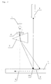
- the equipment for measurement of the tested product by creation of an optical 3D model consists of a white light source (1) with a continuous spectrum, an optical prism (2), a line-scanning camera (3) and an optical unit (4) for rectifying the white light into the beam.
- the light is rectified by the optical unit (4) into a parallel, narrow beam which then passes through the optical prism (2) which mediates the disintegration of the light into the spectrum. ( Fig. 5 ).
- the light which enters into the prism (2) contains all colour elements.
- the white light disintegrates into individual colours as per the law of light fraction.
- the individual parts are monochromatic and are reflected as a spectrum.
- the width (6) of this spectrum directly influences the resolution in the Z-axis.
- the line camera (3) (single row) gradually scans the tested surface line by line by which it is moved.
- the geometric position of the camera (3) and the light is the same during the whole period of scanning.
- the camera (3) and the light are adjusted to zero height (ground) so that the camera (3) displays the starting (7) of the spectrum, i.e. the red colour. All non-zero heights are displayed in another colour as they are in the colour spectrum.
- the manner of measurement of the tested product consists of several steps.
- the first step is the calibration of the colour spectrum for [mm] of the height. This is performed by scanning the declination of the area where the angle of the declination is known in advance with high precision.
- a further step is testing consisting of the scanning of the surface.
- the image produced by the camera composites from individual images, displays all parts on the surface. Dimensions in the axes x and y correspond to the actual dimensions of the recorded item.
- the colour reflection of the item corresponds to its height above the surface.
- the software calculates (according to the function acquired during the calibration) the ascertained values of the colour part [R,G,B] of the individual pixels for the actual height (z-axis). In the actual tested area the software directly returns the values of the height (e.g. the upper area of the condenser).
- the technical solution for the invention can be particularly used for approximate or target inspection of the geometry and measurement of the distance of individual products or their parts, particularly where there is the necessity to optically measure the distance between the sensor and the tested part, i.e. in the direction in which the change is not reflected on the image in the normal status.
Landscapes
- Physics & Mathematics (AREA)
- General Physics & Mathematics (AREA)
- Engineering & Computer Science (AREA)
- Computer Vision & Pattern Recognition (AREA)
- Length Measuring Devices By Optical Means (AREA)
Priority Applications (10)
| Application Number | Priority Date | Filing Date | Title |
|---|---|---|---|
| PCT/IB2010/000944 WO2010100571A1 (en) | 2009-03-03 | 2010-03-02 | Method and device for optically measuring the surface of a product |
| AT10721199T ATE557260T1 (de) | 2009-03-03 | 2010-03-02 | Verfahren und vorrichtung zur optischen messung der oberfläche eines produkts |
| US13/201,808 US20120033066A1 (en) | 2009-03-03 | 2010-03-02 | Method and device for optically measuring the surface of a product |
| PT10721199T PT2307852E (pt) | 2009-03-03 | 2010-03-02 | Método e dispositivo para medição óptica da superfície de um produto |
| MX2011009114A MX2011009114A (es) | 2009-03-03 | 2010-03-02 | Procedimiento y dispositivo para medir opticamente la superficie de un producto. |
| BRPI1009508A BRPI1009508A2 (pt) | 2009-03-03 | 2010-03-02 | método e dispositivo para medição óptica da superfície de um produto |
| RU2011139987/28A RU2500984C2 (ru) | 2009-03-03 | 2010-03-02 | Способ и устройство для оптического измерения поверхности изделия |
| ES10721199T ES2390487T3 (es) | 2009-03-03 | 2010-03-02 | Procedimiento y dispositivo para medir ópticamente la superficie de un producto |
| CN201080002245.8A CN102282440B (zh) | 2009-03-03 | 2010-03-02 | 用于光学地测量产品表面的方法和设备 |
| EP10721199A EP2307852B1 (de) | 2009-03-03 | 2010-03-02 | Verfahren und vorrichtung zur optischen messung der oberfläche eines produkts |
Applications Claiming Priority (2)
| Application Number | Priority Date | Filing Date | Title |
|---|---|---|---|
| CZ20080793A CZ2008793A3 (cs) | 2008-12-09 | 2008-12-09 | Zarízení a zpusob kontroly geometrie plochy rovinného a zakriveného plastového nebo skleneného výrobku pomocí svetelné bodové síte nebo vzoru využívající rozptyl svetla na povrchu nebo rozhraní dvou materiálu a jeho použití |
| CZ20090133A CZ2009133A3 (cs) | 2009-03-03 | 2009-03-03 | Zarízení, zpusob merení vnejších rozmeru testovaného výrobku a použití tohoto zarízení |
Publications (1)
| Publication Number | Publication Date |
|---|---|
| EP2196765A1 true EP2196765A1 (de) | 2010-06-16 |
Family
ID=41282722
Family Applications (1)
| Application Number | Title | Priority Date | Filing Date |
|---|---|---|---|
| EP09466016A Withdrawn EP2196765A1 (de) | 2008-12-09 | 2009-08-27 | Messen der Außenmaße eines Objektes |
Country Status (1)
| Country | Link |
|---|---|
| EP (1) | EP2196765A1 (de) |
Cited By (2)
| Publication number | Priority date | Publication date | Assignee | Title |
|---|---|---|---|---|
| WO2014158483A1 (en) * | 2013-03-12 | 2014-10-02 | Illinois Tool Works Inc. | Color-based linear three dimensional acquisition system and method |
| CN112985277A (zh) * | 2019-12-13 | 2021-06-18 | 株式会社三丰 | 用于测量测试表面的高度图的方法 |
Citations (2)
| Publication number | Priority date | Publication date | Assignee | Title |
|---|---|---|---|---|
| JPS6175210A (ja) * | 1984-09-20 | 1986-04-17 | Nec Corp | レンジフアインダ |
| WO2002082009A1 (en) * | 2001-04-06 | 2002-10-17 | Intek Plus Co., Ltd. | Method and apparatus for measuring the three-dimensional surface shape of an object using color informations of light reflected by the object |
-
2009
- 2009-08-27 EP EP09466016A patent/EP2196765A1/de not_active Withdrawn
Patent Citations (2)
| Publication number | Priority date | Publication date | Assignee | Title |
|---|---|---|---|---|
| JPS6175210A (ja) * | 1984-09-20 | 1986-04-17 | Nec Corp | レンジフアインダ |
| WO2002082009A1 (en) * | 2001-04-06 | 2002-10-17 | Intek Plus Co., Ltd. | Method and apparatus for measuring the three-dimensional surface shape of an object using color informations of light reflected by the object |
Cited By (3)
| Publication number | Priority date | Publication date | Assignee | Title |
|---|---|---|---|---|
| WO2014158483A1 (en) * | 2013-03-12 | 2014-10-02 | Illinois Tool Works Inc. | Color-based linear three dimensional acquisition system and method |
| US8939074B2 (en) | 2013-03-12 | 2015-01-27 | Illinois Tool Works Inc. | Color-based linear three dimensional acquisition system and method |
| CN112985277A (zh) * | 2019-12-13 | 2021-06-18 | 株式会社三丰 | 用于测量测试表面的高度图的方法 |
Similar Documents
| Publication | Publication Date | Title |
|---|---|---|
| EP2307852B1 (de) | Verfahren und vorrichtung zur optischen messung der oberfläche eines produkts | |
| US9903710B2 (en) | Shape inspection apparatus for metallic body and shape inspection method for metallic body | |
| US11199395B2 (en) | Profile inspection system for threaded and axial components | |
| CN108332708B (zh) | 激光水平仪自动检测系统及检测方法 | |
| TWI396824B (zh) | 用於光學測量產品表面之方法及器件 | |
| CN102305588B (zh) | 一种双激光复合式影像测量系统 | |
| CN101479596A (zh) | 玻璃窗检验方法 | |
| US11092432B2 (en) | Reference plate and method for calibrating and/or checking a deflectometry sensor system | |
| CN107084927B (zh) | 基板色度检测方法及装置 | |
| US8553082B2 (en) | Distortion inspecting apparatus and distortion inspecting method | |
| CN113251939A (zh) | 一种非接触式铁路继电器接点间隙的测量方法 | |
| CN211452221U (zh) | 一种通用零件尺寸测试仪 | |
| CN113281343A (zh) | 一种对多层透明材料进行缺陷检测的系统及方法 | |
| CN107884049A (zh) | 一种产品称重及三维尺寸测量装置 | |
| JP2004004073A (ja) | 3次元測定システムにおけるセンサ位置合わせ方法 | |
| CN204346405U (zh) | 钩舌曲面检测装置和检测仪 | |
| EP2196765A1 (de) | Messen der Außenmaße eines Objektes | |
| CN110470250B (zh) | 一种零件表面平面度的检测装置及检测方法 | |
| Harding | Industrial metrology: Engineering precision. | |
| CN209858420U (zh) | 一种镀膜玻璃颜色检测机构 | |
| CN208187381U (zh) | 激光水平仪自动检测系统 | |
| CN107014323B (zh) | 一种点激光共面度测试装置及其方法 | |
| Hemming et al. | Calibration of dial indicators using machine vision | |
| CN114858273A (zh) | 一种显示模组空间位置的光学色差测量方法 | |
| CN118463826B (zh) | 半导体载片台的精度测量系统、方法以及存储介质 |
Legal Events
| Date | Code | Title | Description |
|---|---|---|---|
| PUAI | Public reference made under article 153(3) epc to a published international application that has entered the european phase |
Free format text: ORIGINAL CODE: 0009012 |
|
| STAA | Information on the status of an ep patent application or granted ep patent |
Free format text: STATUS: THE APPLICATION HAS BEEN WITHDRAWN |
|
| AK | Designated contracting states |
Kind code of ref document: A1 Designated state(s): AT BE BG CH CY CZ DE DK EE ES FI FR GB GR HR HU IE IS IT LI LT LU LV MC MK MT NL NO PL PT RO SE SI SK SM TR |
|
| AX | Request for extension of the european patent |
Extension state: AL BA RS |
|
| 18W | Application withdrawn |
Effective date: 20100528 |