EP2197513B1 - Blutkreislaufanordnung für eine Dialyseeinheit - Google Patents
Blutkreislaufanordnung für eine Dialyseeinheit Download PDFInfo
- Publication number
- EP2197513B1 EP2197513B1 EP08838971.3A EP08838971A EP2197513B1 EP 2197513 B1 EP2197513 B1 EP 2197513B1 EP 08838971 A EP08838971 A EP 08838971A EP 2197513 B1 EP2197513 B1 EP 2197513B1
- Authority
- EP
- European Patent Office
- Prior art keywords
- blood
- pump
- circuit assembly
- blood circuit
- dialysis unit
- Prior art date
- Legal status (The legal status is an assumption and is not a legal conclusion. Google has not performed a legal analysis and makes no representation as to the accuracy of the status listed.)
- Active
Links
Images














Classifications
-
- A—HUMAN NECESSITIES
- A61—MEDICAL OR VETERINARY SCIENCE; HYGIENE
- A61M—DEVICES FOR INTRODUCING MEDIA INTO, OR ONTO, THE BODY; DEVICES FOR TRANSDUCING BODY MEDIA OR FOR TAKING MEDIA FROM THE BODY; DEVICES FOR PRODUCING OR ENDING SLEEP OR STUPOR
- A61M1/00—Suction or pumping devices for medical purposes; Devices for carrying-off, for treatment of, or for carrying-over, body-liquids; Drainage systems
- A61M1/14—Dialysis systems; Artificial kidneys; Blood oxygenators ; Reciprocating systems for treatment of body fluids, e.g. single needle systems for hemofiltration or pheresis
- A61M1/16—Dialysis systems; Artificial kidneys; Blood oxygenators ; Reciprocating systems for treatment of body fluids, e.g. single needle systems for hemofiltration or pheresis with membranes
- A61M1/1654—Dialysates therefor
- A61M1/1656—Apparatus for preparing dialysates
-
- A—HUMAN NECESSITIES
- A61—MEDICAL OR VETERINARY SCIENCE; HYGIENE
- A61M—DEVICES FOR INTRODUCING MEDIA INTO, OR ONTO, THE BODY; DEVICES FOR TRANSDUCING BODY MEDIA OR FOR TAKING MEDIA FROM THE BODY; DEVICES FOR PRODUCING OR ENDING SLEEP OR STUPOR
- A61M1/00—Suction or pumping devices for medical purposes; Devices for carrying-off, for treatment of, or for carrying-over, body-liquids; Drainage systems
- A61M1/14—Dialysis systems; Artificial kidneys; Blood oxygenators ; Reciprocating systems for treatment of body fluids, e.g. single needle systems for hemofiltration or pheresis
- A61M1/15—Dialysis systems; Artificial kidneys; Blood oxygenators ; Reciprocating systems for treatment of body fluids, e.g. single needle systems for hemofiltration or pheresis with a cassette forming partially or totally the flow circuit for the treating fluid, e.g. the dialysate fluid circuit or the treating gas circuit
- A61M1/155—Dialysis systems; Artificial kidneys; Blood oxygenators ; Reciprocating systems for treatment of body fluids, e.g. single needle systems for hemofiltration or pheresis with a cassette forming partially or totally the flow circuit for the treating fluid, e.g. the dialysate fluid circuit or the treating gas circuit with treatment-fluid pumping means or components thereof
-
- A—HUMAN NECESSITIES
- A61—MEDICAL OR VETERINARY SCIENCE; HYGIENE
- A61M—DEVICES FOR INTRODUCING MEDIA INTO, OR ONTO, THE BODY; DEVICES FOR TRANSDUCING BODY MEDIA OR FOR TAKING MEDIA FROM THE BODY; DEVICES FOR PRODUCING OR ENDING SLEEP OR STUPOR
- A61M1/00—Suction or pumping devices for medical purposes; Devices for carrying-off, for treatment of, or for carrying-over, body-liquids; Drainage systems
- A61M1/14—Dialysis systems; Artificial kidneys; Blood oxygenators ; Reciprocating systems for treatment of body fluids, e.g. single needle systems for hemofiltration or pheresis
- A61M1/15—Dialysis systems; Artificial kidneys; Blood oxygenators ; Reciprocating systems for treatment of body fluids, e.g. single needle systems for hemofiltration or pheresis with a cassette forming partially or totally the flow circuit for the treating fluid, e.g. the dialysate fluid circuit or the treating gas circuit
- A61M1/156—Constructional details of the cassette, e.g. specific details on material or shape
- A61M1/1565—Details of valves
-
- A—HUMAN NECESSITIES
- A61—MEDICAL OR VETERINARY SCIENCE; HYGIENE
- A61M—DEVICES FOR INTRODUCING MEDIA INTO, OR ONTO, THE BODY; DEVICES FOR TRANSDUCING BODY MEDIA OR FOR TAKING MEDIA FROM THE BODY; DEVICES FOR PRODUCING OR ENDING SLEEP OR STUPOR
- A61M1/00—Suction or pumping devices for medical purposes; Devices for carrying-off, for treatment of, or for carrying-over, body-liquids; Drainage systems
- A61M1/14—Dialysis systems; Artificial kidneys; Blood oxygenators ; Reciprocating systems for treatment of body fluids, e.g. single needle systems for hemofiltration or pheresis
- A61M1/16—Dialysis systems; Artificial kidneys; Blood oxygenators ; Reciprocating systems for treatment of body fluids, e.g. single needle systems for hemofiltration or pheresis with membranes
-
- A—HUMAN NECESSITIES
- A61—MEDICAL OR VETERINARY SCIENCE; HYGIENE
- A61M—DEVICES FOR INTRODUCING MEDIA INTO, OR ONTO, THE BODY; DEVICES FOR TRANSDUCING BODY MEDIA OR FOR TAKING MEDIA FROM THE BODY; DEVICES FOR PRODUCING OR ENDING SLEEP OR STUPOR
- A61M1/00—Suction or pumping devices for medical purposes; Devices for carrying-off, for treatment of, or for carrying-over, body-liquids; Drainage systems
- A61M1/14—Dialysis systems; Artificial kidneys; Blood oxygenators ; Reciprocating systems for treatment of body fluids, e.g. single needle systems for hemofiltration or pheresis
- A61M1/16—Dialysis systems; Artificial kidneys; Blood oxygenators ; Reciprocating systems for treatment of body fluids, e.g. single needle systems for hemofiltration or pheresis with membranes
- A61M1/1601—Control or regulation
- A61M1/1603—Regulation parameters
- A61M1/1605—Physical characteristics of the dialysate fluid
-
- A—HUMAN NECESSITIES
- A61—MEDICAL OR VETERINARY SCIENCE; HYGIENE
- A61M—DEVICES FOR INTRODUCING MEDIA INTO, OR ONTO, THE BODY; DEVICES FOR TRANSDUCING BODY MEDIA OR FOR TAKING MEDIA FROM THE BODY; DEVICES FOR PRODUCING OR ENDING SLEEP OR STUPOR
- A61M1/00—Suction or pumping devices for medical purposes; Devices for carrying-off, for treatment of, or for carrying-over, body-liquids; Drainage systems
- A61M1/14—Dialysis systems; Artificial kidneys; Blood oxygenators ; Reciprocating systems for treatment of body fluids, e.g. single needle systems for hemofiltration or pheresis
- A61M1/16—Dialysis systems; Artificial kidneys; Blood oxygenators ; Reciprocating systems for treatment of body fluids, e.g. single needle systems for hemofiltration or pheresis with membranes
- A61M1/1621—Constructional aspects thereof
- A61M1/1633—Constructional aspects thereof with more than one dialyser unit
-
- A—HUMAN NECESSITIES
- A61—MEDICAL OR VETERINARY SCIENCE; HYGIENE
- A61M—DEVICES FOR INTRODUCING MEDIA INTO, OR ONTO, THE BODY; DEVICES FOR TRANSDUCING BODY MEDIA OR FOR TAKING MEDIA FROM THE BODY; DEVICES FOR PRODUCING OR ENDING SLEEP OR STUPOR
- A61M1/00—Suction or pumping devices for medical purposes; Devices for carrying-off, for treatment of, or for carrying-over, body-liquids; Drainage systems
- A61M1/14—Dialysis systems; Artificial kidneys; Blood oxygenators ; Reciprocating systems for treatment of body fluids, e.g. single needle systems for hemofiltration or pheresis
- A61M1/16—Dialysis systems; Artificial kidneys; Blood oxygenators ; Reciprocating systems for treatment of body fluids, e.g. single needle systems for hemofiltration or pheresis with membranes
- A61M1/1621—Constructional aspects thereof
- A61M1/1635—Constructional aspects thereof with volume chamber balancing devices between used and fresh dialysis fluid
- A61M1/1639—Constructional aspects thereof with volume chamber balancing devices between used and fresh dialysis fluid linked by membranes
-
- A—HUMAN NECESSITIES
- A61—MEDICAL OR VETERINARY SCIENCE; HYGIENE
- A61M—DEVICES FOR INTRODUCING MEDIA INTO, OR ONTO, THE BODY; DEVICES FOR TRANSDUCING BODY MEDIA OR FOR TAKING MEDIA FROM THE BODY; DEVICES FOR PRODUCING OR ENDING SLEEP OR STUPOR
- A61M1/00—Suction or pumping devices for medical purposes; Devices for carrying-off, for treatment of, or for carrying-over, body-liquids; Drainage systems
- A61M1/14—Dialysis systems; Artificial kidneys; Blood oxygenators ; Reciprocating systems for treatment of body fluids, e.g. single needle systems for hemofiltration or pheresis
- A61M1/16—Dialysis systems; Artificial kidneys; Blood oxygenators ; Reciprocating systems for treatment of body fluids, e.g. single needle systems for hemofiltration or pheresis with membranes
- A61M1/1654—Dialysates therefor
- A61M1/1656—Apparatus for preparing dialysates
- A61M1/166—Heating
- A61M1/1662—Heating with heat exchange between fresh and used dialysate
-
- A—HUMAN NECESSITIES
- A61—MEDICAL OR VETERINARY SCIENCE; HYGIENE
- A61M—DEVICES FOR INTRODUCING MEDIA INTO, OR ONTO, THE BODY; DEVICES FOR TRANSDUCING BODY MEDIA OR FOR TAKING MEDIA FROM THE BODY; DEVICES FOR PRODUCING OR ENDING SLEEP OR STUPOR
- A61M1/00—Suction or pumping devices for medical purposes; Devices for carrying-off, for treatment of, or for carrying-over, body-liquids; Drainage systems
- A61M1/14—Dialysis systems; Artificial kidneys; Blood oxygenators ; Reciprocating systems for treatment of body fluids, e.g. single needle systems for hemofiltration or pheresis
- A61M1/16—Dialysis systems; Artificial kidneys; Blood oxygenators ; Reciprocating systems for treatment of body fluids, e.g. single needle systems for hemofiltration or pheresis with membranes
- A61M1/1654—Dialysates therefor
- A61M1/1656—Apparatus for preparing dialysates
- A61M1/166—Heating
- A61M1/1664—Heating with temperature control
-
- A—HUMAN NECESSITIES
- A61—MEDICAL OR VETERINARY SCIENCE; HYGIENE
- A61M—DEVICES FOR INTRODUCING MEDIA INTO, OR ONTO, THE BODY; DEVICES FOR TRANSDUCING BODY MEDIA OR FOR TAKING MEDIA FROM THE BODY; DEVICES FOR PRODUCING OR ENDING SLEEP OR STUPOR
- A61M1/00—Suction or pumping devices for medical purposes; Devices for carrying-off, for treatment of, or for carrying-over, body-liquids; Drainage systems
- A61M1/14—Dialysis systems; Artificial kidneys; Blood oxygenators ; Reciprocating systems for treatment of body fluids, e.g. single needle systems for hemofiltration or pheresis
- A61M1/16—Dialysis systems; Artificial kidneys; Blood oxygenators ; Reciprocating systems for treatment of body fluids, e.g. single needle systems for hemofiltration or pheresis with membranes
- A61M1/1654—Dialysates therefor
- A61M1/1656—Apparatus for preparing dialysates
- A61M1/1666—Apparatus for preparing dialysates by dissolving solids
-
- A—HUMAN NECESSITIES
- A61—MEDICAL OR VETERINARY SCIENCE; HYGIENE
- A61M—DEVICES FOR INTRODUCING MEDIA INTO, OR ONTO, THE BODY; DEVICES FOR TRANSDUCING BODY MEDIA OR FOR TAKING MEDIA FROM THE BODY; DEVICES FOR PRODUCING OR ENDING SLEEP OR STUPOR
- A61M1/00—Suction or pumping devices for medical purposes; Devices for carrying-off, for treatment of, or for carrying-over, body-liquids; Drainage systems
- A61M1/14—Dialysis systems; Artificial kidneys; Blood oxygenators ; Reciprocating systems for treatment of body fluids, e.g. single needle systems for hemofiltration or pheresis
- A61M1/16—Dialysis systems; Artificial kidneys; Blood oxygenators ; Reciprocating systems for treatment of body fluids, e.g. single needle systems for hemofiltration or pheresis with membranes
- A61M1/1654—Dialysates therefor
- A61M1/1656—Apparatus for preparing dialysates
- A61M1/1672—Apparatus for preparing dialysates using membrane filters, e.g. for sterilising the dialysate
-
- A—HUMAN NECESSITIES
- A61—MEDICAL OR VETERINARY SCIENCE; HYGIENE
- A61M—DEVICES FOR INTRODUCING MEDIA INTO, OR ONTO, THE BODY; DEVICES FOR TRANSDUCING BODY MEDIA OR FOR TAKING MEDIA FROM THE BODY; DEVICES FOR PRODUCING OR ENDING SLEEP OR STUPOR
- A61M1/00—Suction or pumping devices for medical purposes; Devices for carrying-off, for treatment of, or for carrying-over, body-liquids; Drainage systems
- A61M1/14—Dialysis systems; Artificial kidneys; Blood oxygenators ; Reciprocating systems for treatment of body fluids, e.g. single needle systems for hemofiltration or pheresis
- A61M1/16—Dialysis systems; Artificial kidneys; Blood oxygenators ; Reciprocating systems for treatment of body fluids, e.g. single needle systems for hemofiltration or pheresis with membranes
- A61M1/168—Sterilisation or cleaning before or after use
- A61M1/1682—Sterilisation or cleaning before or after use both machine and membrane module, i.e. also the module blood side
-
- A—HUMAN NECESSITIES
- A61—MEDICAL OR VETERINARY SCIENCE; HYGIENE
- A61M—DEVICES FOR INTRODUCING MEDIA INTO, OR ONTO, THE BODY; DEVICES FOR TRANSDUCING BODY MEDIA OR FOR TAKING MEDIA FROM THE BODY; DEVICES FOR PRODUCING OR ENDING SLEEP OR STUPOR
- A61M1/00—Suction or pumping devices for medical purposes; Devices for carrying-off, for treatment of, or for carrying-over, body-liquids; Drainage systems
- A61M1/14—Dialysis systems; Artificial kidneys; Blood oxygenators ; Reciprocating systems for treatment of body fluids, e.g. single needle systems for hemofiltration or pheresis
- A61M1/16—Dialysis systems; Artificial kidneys; Blood oxygenators ; Reciprocating systems for treatment of body fluids, e.g. single needle systems for hemofiltration or pheresis with membranes
- A61M1/168—Sterilisation or cleaning before or after use
- A61M1/1686—Sterilisation or cleaning before or after use by heat
-
- A—HUMAN NECESSITIES
- A61—MEDICAL OR VETERINARY SCIENCE; HYGIENE
- A61M—DEVICES FOR INTRODUCING MEDIA INTO, OR ONTO, THE BODY; DEVICES FOR TRANSDUCING BODY MEDIA OR FOR TAKING MEDIA FROM THE BODY; DEVICES FOR PRODUCING OR ENDING SLEEP OR STUPOR
- A61M1/00—Suction or pumping devices for medical purposes; Devices for carrying-off, for treatment of, or for carrying-over, body-liquids; Drainage systems
- A61M1/34—Filtering material out of the blood by passing it through a membrane, i.e. hemofiltration or diafiltration
-
- A—HUMAN NECESSITIES
- A61—MEDICAL OR VETERINARY SCIENCE; HYGIENE
- A61M—DEVICES FOR INTRODUCING MEDIA INTO, OR ONTO, THE BODY; DEVICES FOR TRANSDUCING BODY MEDIA OR FOR TAKING MEDIA FROM THE BODY; DEVICES FOR PRODUCING OR ENDING SLEEP OR STUPOR
- A61M1/00—Suction or pumping devices for medical purposes; Devices for carrying-off, for treatment of, or for carrying-over, body-liquids; Drainage systems
- A61M1/36—Other treatment of blood in a by-pass of the natural circulatory system, e.g. temperature adaptation, irradiation ; Extra-corporeal blood circuits
- A61M1/3621—Extra-corporeal blood circuits
-
- A—HUMAN NECESSITIES
- A61—MEDICAL OR VETERINARY SCIENCE; HYGIENE
- A61M—DEVICES FOR INTRODUCING MEDIA INTO, OR ONTO, THE BODY; DEVICES FOR TRANSDUCING BODY MEDIA OR FOR TAKING MEDIA FROM THE BODY; DEVICES FOR PRODUCING OR ENDING SLEEP OR STUPOR
- A61M1/00—Suction or pumping devices for medical purposes; Devices for carrying-off, for treatment of, or for carrying-over, body-liquids; Drainage systems
- A61M1/36—Other treatment of blood in a by-pass of the natural circulatory system, e.g. temperature adaptation, irradiation ; Extra-corporeal blood circuits
- A61M1/3621—Extra-corporeal blood circuits
- A61M1/3622—Extra-corporeal blood circuits with a cassette forming partially or totally the blood circuit
- A61M1/36225—Extra-corporeal blood circuits with a cassette forming partially or totally the blood circuit with blood pumping means or components thereof
-
- A—HUMAN NECESSITIES
- A61—MEDICAL OR VETERINARY SCIENCE; HYGIENE
- A61M—DEVICES FOR INTRODUCING MEDIA INTO, OR ONTO, THE BODY; DEVICES FOR TRANSDUCING BODY MEDIA OR FOR TAKING MEDIA FROM THE BODY; DEVICES FOR PRODUCING OR ENDING SLEEP OR STUPOR
- A61M1/00—Suction or pumping devices for medical purposes; Devices for carrying-off, for treatment of, or for carrying-over, body-liquids; Drainage systems
- A61M1/36—Other treatment of blood in a by-pass of the natural circulatory system, e.g. temperature adaptation, irradiation ; Extra-corporeal blood circuits
- A61M1/3621—Extra-corporeal blood circuits
- A61M1/3622—Extra-corporeal blood circuits with a cassette forming partially or totally the blood circuit
- A61M1/36226—Constructional details of cassettes, e.g. specific details on material or shape
- A61M1/362262—Details of incorporated reservoirs
-
- A—HUMAN NECESSITIES
- A61—MEDICAL OR VETERINARY SCIENCE; HYGIENE
- A61M—DEVICES FOR INTRODUCING MEDIA INTO, OR ONTO, THE BODY; DEVICES FOR TRANSDUCING BODY MEDIA OR FOR TAKING MEDIA FROM THE BODY; DEVICES FOR PRODUCING OR ENDING SLEEP OR STUPOR
- A61M1/00—Suction or pumping devices for medical purposes; Devices for carrying-off, for treatment of, or for carrying-over, body-liquids; Drainage systems
- A61M1/36—Other treatment of blood in a by-pass of the natural circulatory system, e.g. temperature adaptation, irradiation ; Extra-corporeal blood circuits
- A61M1/3621—Extra-corporeal blood circuits
- A61M1/3622—Extra-corporeal blood circuits with a cassette forming partially or totally the blood circuit
- A61M1/36226—Constructional details of cassettes, e.g. specific details on material or shape
- A61M1/362263—Details of incorporated filters
-
- A—HUMAN NECESSITIES
- A61—MEDICAL OR VETERINARY SCIENCE; HYGIENE
- A61M—DEVICES FOR INTRODUCING MEDIA INTO, OR ONTO, THE BODY; DEVICES FOR TRANSDUCING BODY MEDIA OR FOR TAKING MEDIA FROM THE BODY; DEVICES FOR PRODUCING OR ENDING SLEEP OR STUPOR
- A61M1/00—Suction or pumping devices for medical purposes; Devices for carrying-off, for treatment of, or for carrying-over, body-liquids; Drainage systems
- A61M1/36—Other treatment of blood in a by-pass of the natural circulatory system, e.g. temperature adaptation, irradiation ; Extra-corporeal blood circuits
- A61M1/3621—Extra-corporeal blood circuits
- A61M1/3622—Extra-corporeal blood circuits with a cassette forming partially or totally the blood circuit
- A61M1/36226—Constructional details of cassettes, e.g. specific details on material or shape
- A61M1/362265—Details of valves
-
- A—HUMAN NECESSITIES
- A61—MEDICAL OR VETERINARY SCIENCE; HYGIENE
- A61M—DEVICES FOR INTRODUCING MEDIA INTO, OR ONTO, THE BODY; DEVICES FOR TRANSDUCING BODY MEDIA OR FOR TAKING MEDIA FROM THE BODY; DEVICES FOR PRODUCING OR ENDING SLEEP OR STUPOR
- A61M1/00—Suction or pumping devices for medical purposes; Devices for carrying-off, for treatment of, or for carrying-over, body-liquids; Drainage systems
- A61M1/36—Other treatment of blood in a by-pass of the natural circulatory system, e.g. temperature adaptation, irradiation ; Extra-corporeal blood circuits
- A61M1/3621—Extra-corporeal blood circuits
- A61M1/3622—Extra-corporeal blood circuits with a cassette forming partially or totally the blood circuit
- A61M1/36226—Constructional details of cassettes, e.g. specific details on material or shape
- A61M1/362266—Means for adding solutions or substances to the blood
-
- A—HUMAN NECESSITIES
- A61—MEDICAL OR VETERINARY SCIENCE; HYGIENE
- A61M—DEVICES FOR INTRODUCING MEDIA INTO, OR ONTO, THE BODY; DEVICES FOR TRANSDUCING BODY MEDIA OR FOR TAKING MEDIA FROM THE BODY; DEVICES FOR PRODUCING OR ENDING SLEEP OR STUPOR
- A61M1/00—Suction or pumping devices for medical purposes; Devices for carrying-off, for treatment of, or for carrying-over, body-liquids; Drainage systems
- A61M1/84—Drainage tubes; Aspiration tips
- A61M1/842—Drainage tubes; Aspiration tips rotating
-
- A—HUMAN NECESSITIES
- A61—MEDICAL OR VETERINARY SCIENCE; HYGIENE
- A61M—DEVICES FOR INTRODUCING MEDIA INTO, OR ONTO, THE BODY; DEVICES FOR TRANSDUCING BODY MEDIA OR FOR TAKING MEDIA FROM THE BODY; DEVICES FOR PRODUCING OR ENDING SLEEP OR STUPOR
- A61M1/00—Suction or pumping devices for medical purposes; Devices for carrying-off, for treatment of, or for carrying-over, body-liquids; Drainage systems
- A61M1/84—Drainage tubes; Aspiration tips
- A61M1/85—Drainage tubes; Aspiration tips with gas or fluid supply means, e.g. for supplying rinsing fluids or anticoagulants
-
- A—HUMAN NECESSITIES
- A61—MEDICAL OR VETERINARY SCIENCE; HYGIENE
- A61M—DEVICES FOR INTRODUCING MEDIA INTO, OR ONTO, THE BODY; DEVICES FOR TRANSDUCING BODY MEDIA OR FOR TAKING MEDIA FROM THE BODY; DEVICES FOR PRODUCING OR ENDING SLEEP OR STUPOR
- A61M39/00—Tubes, tube connectors, tube couplings, valves, access sites or the like, specially adapted for medical use
- A61M39/10—Tube connectors; Tube couplings
- A61M39/1011—Locking means for securing connection; Additional tamper safeties
-
- A—HUMAN NECESSITIES
- A61—MEDICAL OR VETERINARY SCIENCE; HYGIENE
- A61M—DEVICES FOR INTRODUCING MEDIA INTO, OR ONTO, THE BODY; DEVICES FOR TRANSDUCING BODY MEDIA OR FOR TAKING MEDIA FROM THE BODY; DEVICES FOR PRODUCING OR ENDING SLEEP OR STUPOR
- A61M60/00—Blood pumps; Devices for mechanical circulatory actuation; Balloon pumps for circulatory assistance
- A61M60/10—Location thereof with respect to the patient's body
- A61M60/104—Extracorporeal pumps, i.e. the blood being pumped outside the patient's body
- A61M60/109—Extracorporeal pumps, i.e. the blood being pumped outside the patient's body incorporated within extracorporeal blood circuits or systems
- A61M60/113—Extracorporeal pumps, i.e. the blood being pumped outside the patient's body incorporated within extracorporeal blood circuits or systems in other functional devices, e.g. dialysers or heart-lung machines
-
- A—HUMAN NECESSITIES
- A61—MEDICAL OR VETERINARY SCIENCE; HYGIENE
- A61M—DEVICES FOR INTRODUCING MEDIA INTO, OR ONTO, THE BODY; DEVICES FOR TRANSDUCING BODY MEDIA OR FOR TAKING MEDIA FROM THE BODY; DEVICES FOR PRODUCING OR ENDING SLEEP OR STUPOR
- A61M60/00—Blood pumps; Devices for mechanical circulatory actuation; Balloon pumps for circulatory assistance
- A61M60/30—Medical purposes thereof other than the enhancement of the cardiac output
- A61M60/36—Medical purposes thereof other than the enhancement of the cardiac output for specific blood treatment; for specific therapy
- A61M60/37—Haemodialysis, haemofiltration or diafiltration
-
- A—HUMAN NECESSITIES
- A61—MEDICAL OR VETERINARY SCIENCE; HYGIENE
- A61M—DEVICES FOR INTRODUCING MEDIA INTO, OR ONTO, THE BODY; DEVICES FOR TRANSDUCING BODY MEDIA OR FOR TAKING MEDIA FROM THE BODY; DEVICES FOR PRODUCING OR ENDING SLEEP OR STUPOR
- A61M60/00—Blood pumps; Devices for mechanical circulatory actuation; Balloon pumps for circulatory assistance
- A61M60/40—Details relating to driving
- A61M60/424—Details relating to driving for positive displacement blood pumps
- A61M60/427—Details relating to driving for positive displacement blood pumps the force acting on the blood contacting member being hydraulic or pneumatic
- A61M60/43—Details relating to driving for positive displacement blood pumps the force acting on the blood contacting member being hydraulic or pneumatic using vacuum at the blood pump, e.g. to accelerate filling
-
- A—HUMAN NECESSITIES
- A61—MEDICAL OR VETERINARY SCIENCE; HYGIENE
- A61M—DEVICES FOR INTRODUCING MEDIA INTO, OR ONTO, THE BODY; DEVICES FOR TRANSDUCING BODY MEDIA OR FOR TAKING MEDIA FROM THE BODY; DEVICES FOR PRODUCING OR ENDING SLEEP OR STUPOR
- A61M60/00—Blood pumps; Devices for mechanical circulatory actuation; Balloon pumps for circulatory assistance
- A61M60/50—Details relating to control
- A61M60/508—Electronic control means, e.g. for feedback regulation
-
- A—HUMAN NECESSITIES
- A61—MEDICAL OR VETERINARY SCIENCE; HYGIENE
- A61M—DEVICES FOR INTRODUCING MEDIA INTO, OR ONTO, THE BODY; DEVICES FOR TRANSDUCING BODY MEDIA OR FOR TAKING MEDIA FROM THE BODY; DEVICES FOR PRODUCING OR ENDING SLEEP OR STUPOR
- A61M60/00—Blood pumps; Devices for mechanical circulatory actuation; Balloon pumps for circulatory assistance
- A61M60/80—Constructional details other than related to driving
- A61M60/839—Constructional details other than related to driving of devices for mechanical circulatory actuation
-
- A—HUMAN NECESSITIES
- A61—MEDICAL OR VETERINARY SCIENCE; HYGIENE
- A61M—DEVICES FOR INTRODUCING MEDIA INTO, OR ONTO, THE BODY; DEVICES FOR TRANSDUCING BODY MEDIA OR FOR TAKING MEDIA FROM THE BODY; DEVICES FOR PRODUCING OR ENDING SLEEP OR STUPOR
- A61M60/00—Blood pumps; Devices for mechanical circulatory actuation; Balloon pumps for circulatory assistance
- A61M60/80—Constructional details other than related to driving
- A61M60/845—Constructional details other than related to driving of extracorporeal blood pumps
- A61M60/847—Constructional details other than related to driving of extracorporeal blood pumps arranged in a cassette
-
- A—HUMAN NECESSITIES
- A61—MEDICAL OR VETERINARY SCIENCE; HYGIENE
- A61M—DEVICES FOR INTRODUCING MEDIA INTO, OR ONTO, THE BODY; DEVICES FOR TRANSDUCING BODY MEDIA OR FOR TAKING MEDIA FROM THE BODY; DEVICES FOR PRODUCING OR ENDING SLEEP OR STUPOR
- A61M60/00—Blood pumps; Devices for mechanical circulatory actuation; Balloon pumps for circulatory assistance
- A61M60/80—Constructional details other than related to driving
- A61M60/845—Constructional details other than related to driving of extracorporeal blood pumps
- A61M60/849—Disposable parts
-
- A—HUMAN NECESSITIES
- A61—MEDICAL OR VETERINARY SCIENCE; HYGIENE
- A61M—DEVICES FOR INTRODUCING MEDIA INTO, OR ONTO, THE BODY; DEVICES FOR TRANSDUCING BODY MEDIA OR FOR TAKING MEDIA FROM THE BODY; DEVICES FOR PRODUCING OR ENDING SLEEP OR STUPOR
- A61M60/00—Blood pumps; Devices for mechanical circulatory actuation; Balloon pumps for circulatory assistance
- A61M60/80—Constructional details other than related to driving
- A61M60/845—Constructional details other than related to driving of extracorporeal blood pumps
- A61M60/851—Valves
-
- B—PERFORMING OPERATIONS; TRANSPORTING
- B01—PHYSICAL OR CHEMICAL PROCESSES OR APPARATUS IN GENERAL
- B01D—SEPARATION
- B01D61/00—Processes of separation using semi-permeable membranes, e.g. dialysis, osmosis or ultrafiltration; Apparatus, accessories or auxiliary operations specially adapted therefor
- B01D61/24—Dialysis ; Membrane extraction
- B01D61/30—Accessories; Auxiliary operation
-
- B—PERFORMING OPERATIONS; TRANSPORTING
- B01—PHYSICAL OR CHEMICAL PROCESSES OR APPARATUS IN GENERAL
- B01D—SEPARATION
- B01D61/00—Processes of separation using semi-permeable membranes, e.g. dialysis, osmosis or ultrafiltration; Apparatus, accessories or auxiliary operations specially adapted therefor
- B01D61/24—Dialysis ; Membrane extraction
- B01D61/32—Controlling or regulating
-
- F—MECHANICAL ENGINEERING; LIGHTING; HEATING; WEAPONS; BLASTING
- F04—POSITIVE - DISPLACEMENT MACHINES FOR LIQUIDS; PUMPS FOR LIQUIDS OR ELASTIC FLUIDS
- F04C—ROTARY-PISTON, OR OSCILLATING-PISTON, POSITIVE-DISPLACEMENT MACHINES FOR LIQUIDS; ROTARY-PISTON, OR OSCILLATING-PISTON, POSITIVE-DISPLACEMENT PUMPS
- F04C5/00—Rotary-piston machines or pumps with the working-chamber walls at least partly resiliently deformable
-
- A—HUMAN NECESSITIES
- A61—MEDICAL OR VETERINARY SCIENCE; HYGIENE
- A61M—DEVICES FOR INTRODUCING MEDIA INTO, OR ONTO, THE BODY; DEVICES FOR TRANSDUCING BODY MEDIA OR FOR TAKING MEDIA FROM THE BODY; DEVICES FOR PRODUCING OR ENDING SLEEP OR STUPOR
- A61M1/00—Suction or pumping devices for medical purposes; Devices for carrying-off, for treatment of, or for carrying-over, body-liquids; Drainage systems
- A61M1/14—Dialysis systems; Artificial kidneys; Blood oxygenators ; Reciprocating systems for treatment of body fluids, e.g. single needle systems for hemofiltration or pheresis
- A61M1/15—Dialysis systems; Artificial kidneys; Blood oxygenators ; Reciprocating systems for treatment of body fluids, e.g. single needle systems for hemofiltration or pheresis with a cassette forming partially or totally the flow circuit for the treating fluid, e.g. the dialysate fluid circuit or the treating gas circuit
- A61M1/156—Constructional details of the cassette, e.g. specific details on material or shape
- A61M1/1563—Details of incorporated filters
-
- A—HUMAN NECESSITIES
- A61—MEDICAL OR VETERINARY SCIENCE; HYGIENE
- A61M—DEVICES FOR INTRODUCING MEDIA INTO, OR ONTO, THE BODY; DEVICES FOR TRANSDUCING BODY MEDIA OR FOR TAKING MEDIA FROM THE BODY; DEVICES FOR PRODUCING OR ENDING SLEEP OR STUPOR
- A61M1/00—Suction or pumping devices for medical purposes; Devices for carrying-off, for treatment of, or for carrying-over, body-liquids; Drainage systems
- A61M1/14—Dialysis systems; Artificial kidneys; Blood oxygenators ; Reciprocating systems for treatment of body fluids, e.g. single needle systems for hemofiltration or pheresis
- A61M1/16—Dialysis systems; Artificial kidneys; Blood oxygenators ; Reciprocating systems for treatment of body fluids, e.g. single needle systems for hemofiltration or pheresis with membranes
- A61M1/1694—Dialysis systems; Artificial kidneys; Blood oxygenators ; Reciprocating systems for treatment of body fluids, e.g. single needle systems for hemofiltration or pheresis with membranes with recirculating dialysing liquid
- A61M1/1696—Dialysis systems; Artificial kidneys; Blood oxygenators ; Reciprocating systems for treatment of body fluids, e.g. single needle systems for hemofiltration or pheresis with membranes with recirculating dialysing liquid with dialysate regeneration
-
- A—HUMAN NECESSITIES
- A61—MEDICAL OR VETERINARY SCIENCE; HYGIENE
- A61M—DEVICES FOR INTRODUCING MEDIA INTO, OR ONTO, THE BODY; DEVICES FOR TRANSDUCING BODY MEDIA OR FOR TAKING MEDIA FROM THE BODY; DEVICES FOR PRODUCING OR ENDING SLEEP OR STUPOR
- A61M1/00—Suction or pumping devices for medical purposes; Devices for carrying-off, for treatment of, or for carrying-over, body-liquids; Drainage systems
- A61M1/36—Other treatment of blood in a by-pass of the natural circulatory system, e.g. temperature adaptation, irradiation ; Extra-corporeal blood circuits
- A61M1/3621—Extra-corporeal blood circuits
- A61M1/3627—Degassing devices; Buffer reservoirs; Drip chambers; Blood filters
-
- A—HUMAN NECESSITIES
- A61—MEDICAL OR VETERINARY SCIENCE; HYGIENE
- A61M—DEVICES FOR INTRODUCING MEDIA INTO, OR ONTO, THE BODY; DEVICES FOR TRANSDUCING BODY MEDIA OR FOR TAKING MEDIA FROM THE BODY; DEVICES FOR PRODUCING OR ENDING SLEEP OR STUPOR
- A61M39/00—Tubes, tube connectors, tube couplings, valves, access sites or the like, specially adapted for medical use
- A61M39/10—Tube connectors; Tube couplings
- A61M2039/1016—Unlocking means providing a secure or comfortable disconnection
-
- A—HUMAN NECESSITIES
- A61—MEDICAL OR VETERINARY SCIENCE; HYGIENE
- A61M—DEVICES FOR INTRODUCING MEDIA INTO, OR ONTO, THE BODY; DEVICES FOR TRANSDUCING BODY MEDIA OR FOR TAKING MEDIA FROM THE BODY; DEVICES FOR PRODUCING OR ENDING SLEEP OR STUPOR
- A61M39/00—Tubes, tube connectors, tube couplings, valves, access sites or the like, specially adapted for medical use
- A61M39/10—Tube connectors; Tube couplings
- A61M2039/1033—Swivel nut connectors, e.g. threaded connectors, bayonet-connectors
-
- A—HUMAN NECESSITIES
- A61—MEDICAL OR VETERINARY SCIENCE; HYGIENE
- A61M—DEVICES FOR INTRODUCING MEDIA INTO, OR ONTO, THE BODY; DEVICES FOR TRANSDUCING BODY MEDIA OR FOR TAKING MEDIA FROM THE BODY; DEVICES FOR PRODUCING OR ENDING SLEEP OR STUPOR
- A61M2205/00—General characteristics of the apparatus
- A61M2205/12—General characteristics of the apparatus with interchangeable cassettes forming partially or totally the fluid circuit
-
- A—HUMAN NECESSITIES
- A61—MEDICAL OR VETERINARY SCIENCE; HYGIENE
- A61M—DEVICES FOR INTRODUCING MEDIA INTO, OR ONTO, THE BODY; DEVICES FOR TRANSDUCING BODY MEDIA OR FOR TAKING MEDIA FROM THE BODY; DEVICES FOR PRODUCING OR ENDING SLEEP OR STUPOR
- A61M2205/00—General characteristics of the apparatus
- A61M2205/33—Controlling, regulating or measuring
- A61M2205/3317—Electromagnetic, inductive or dielectric measuring means
-
- A—HUMAN NECESSITIES
- A61—MEDICAL OR VETERINARY SCIENCE; HYGIENE
- A61M—DEVICES FOR INTRODUCING MEDIA INTO, OR ONTO, THE BODY; DEVICES FOR TRANSDUCING BODY MEDIA OR FOR TAKING MEDIA FROM THE BODY; DEVICES FOR PRODUCING OR ENDING SLEEP OR STUPOR
- A61M2205/00—General characteristics of the apparatus
- A61M2205/33—Controlling, regulating or measuring
- A61M2205/3324—PH measuring means
-
- A—HUMAN NECESSITIES
- A61—MEDICAL OR VETERINARY SCIENCE; HYGIENE
- A61M—DEVICES FOR INTRODUCING MEDIA INTO, OR ONTO, THE BODY; DEVICES FOR TRANSDUCING BODY MEDIA OR FOR TAKING MEDIA FROM THE BODY; DEVICES FOR PRODUCING OR ENDING SLEEP OR STUPOR
- A61M2205/00—General characteristics of the apparatus
- A61M2205/33—Controlling, regulating or measuring
- A61M2205/3331—Pressure; Flow
-
- A—HUMAN NECESSITIES
- A61—MEDICAL OR VETERINARY SCIENCE; HYGIENE
- A61M—DEVICES FOR INTRODUCING MEDIA INTO, OR ONTO, THE BODY; DEVICES FOR TRANSDUCING BODY MEDIA OR FOR TAKING MEDIA FROM THE BODY; DEVICES FOR PRODUCING OR ENDING SLEEP OR STUPOR
- A61M2205/00—General characteristics of the apparatus
- A61M2205/50—General characteristics of the apparatus with microprocessors or computers
-
- A—HUMAN NECESSITIES
- A61—MEDICAL OR VETERINARY SCIENCE; HYGIENE
- A61M—DEVICES FOR INTRODUCING MEDIA INTO, OR ONTO, THE BODY; DEVICES FOR TRANSDUCING BODY MEDIA OR FOR TAKING MEDIA FROM THE BODY; DEVICES FOR PRODUCING OR ENDING SLEEP OR STUPOR
- A61M2205/00—General characteristics of the apparatus
- A61M2205/50—General characteristics of the apparatus with microprocessors or computers
- A61M2205/502—User interfaces, e.g. screens or keyboards
- A61M2205/505—Touch-screens; Virtual keyboard or keypads; Virtual buttons; Soft keys; Mouse touches
-
- A—HUMAN NECESSITIES
- A61—MEDICAL OR VETERINARY SCIENCE; HYGIENE
- A61M—DEVICES FOR INTRODUCING MEDIA INTO, OR ONTO, THE BODY; DEVICES FOR TRANSDUCING BODY MEDIA OR FOR TAKING MEDIA FROM THE BODY; DEVICES FOR PRODUCING OR ENDING SLEEP OR STUPOR
- A61M2205/00—General characteristics of the apparatus
- A61M2205/58—Means for facilitating use, e.g. by people with impaired vision
-
- A—HUMAN NECESSITIES
- A61—MEDICAL OR VETERINARY SCIENCE; HYGIENE
- A61M—DEVICES FOR INTRODUCING MEDIA INTO, OR ONTO, THE BODY; DEVICES FOR TRANSDUCING BODY MEDIA OR FOR TAKING MEDIA FROM THE BODY; DEVICES FOR PRODUCING OR ENDING SLEEP OR STUPOR
- A61M2205/00—General characteristics of the apparatus
- A61M2205/82—Internal energy supply devices
- A61M2205/8218—Gas operated
-
- A—HUMAN NECESSITIES
- A61—MEDICAL OR VETERINARY SCIENCE; HYGIENE
- A61M—DEVICES FOR INTRODUCING MEDIA INTO, OR ONTO, THE BODY; DEVICES FOR TRANSDUCING BODY MEDIA OR FOR TAKING MEDIA FROM THE BODY; DEVICES FOR PRODUCING OR ENDING SLEEP OR STUPOR
- A61M2205/00—General characteristics of the apparatus
- A61M2205/82—Internal energy supply devices
- A61M2205/8218—Gas operated
- A61M2205/8225—Gas operated using incorporated gas cartridges for the driving gas
-
- A—HUMAN NECESSITIES
- A61—MEDICAL OR VETERINARY SCIENCE; HYGIENE
- A61M—DEVICES FOR INTRODUCING MEDIA INTO, OR ONTO, THE BODY; DEVICES FOR TRANSDUCING BODY MEDIA OR FOR TAKING MEDIA FROM THE BODY; DEVICES FOR PRODUCING OR ENDING SLEEP OR STUPOR
- A61M2205/00—General characteristics of the apparatus
- A61M2205/82—Internal energy supply devices
- A61M2205/8262—Internal energy supply devices connectable to external power source, e.g. connecting to automobile battery through the cigarette lighter
-
- A—HUMAN NECESSITIES
- A61—MEDICAL OR VETERINARY SCIENCE; HYGIENE
- A61M—DEVICES FOR INTRODUCING MEDIA INTO, OR ONTO, THE BODY; DEVICES FOR TRANSDUCING BODY MEDIA OR FOR TAKING MEDIA FROM THE BODY; DEVICES FOR PRODUCING OR ENDING SLEEP OR STUPOR
- A61M2209/00—Ancillary equipment
- A61M2209/08—Supports for equipment
-
- A—HUMAN NECESSITIES
- A61—MEDICAL OR VETERINARY SCIENCE; HYGIENE
- A61M—DEVICES FOR INTRODUCING MEDIA INTO, OR ONTO, THE BODY; DEVICES FOR TRANSDUCING BODY MEDIA OR FOR TAKING MEDIA FROM THE BODY; DEVICES FOR PRODUCING OR ENDING SLEEP OR STUPOR
- A61M2209/00—Ancillary equipment
- A61M2209/08—Supports for equipment
- A61M2209/082—Mounting brackets, arm supports for equipment
-
- A—HUMAN NECESSITIES
- A61—MEDICAL OR VETERINARY SCIENCE; HYGIENE
- A61M—DEVICES FOR INTRODUCING MEDIA INTO, OR ONTO, THE BODY; DEVICES FOR TRANSDUCING BODY MEDIA OR FOR TAKING MEDIA FROM THE BODY; DEVICES FOR PRODUCING OR ENDING SLEEP OR STUPOR
- A61M2209/00—Ancillary equipment
- A61M2209/08—Supports for equipment
- A61M2209/084—Supporting bases, stands for equipment
- A61M2209/086—Docking stations
-
- A—HUMAN NECESSITIES
- A61—MEDICAL OR VETERINARY SCIENCE; HYGIENE
- A61M—DEVICES FOR INTRODUCING MEDIA INTO, OR ONTO, THE BODY; DEVICES FOR TRANSDUCING BODY MEDIA OR FOR TAKING MEDIA FROM THE BODY; DEVICES FOR PRODUCING OR ENDING SLEEP OR STUPOR
- A61M39/00—Tubes, tube connectors, tube couplings, valves, access sites or the like, specially adapted for medical use
- A61M39/10—Tube connectors; Tube couplings
- A61M39/105—Multi-channel connectors or couplings, e.g. for connecting multi-lumen tubes
-
- A—HUMAN NECESSITIES
- A61—MEDICAL OR VETERINARY SCIENCE; HYGIENE
- A61M—DEVICES FOR INTRODUCING MEDIA INTO, OR ONTO, THE BODY; DEVICES FOR TRANSDUCING BODY MEDIA OR FOR TAKING MEDIA FROM THE BODY; DEVICES FOR PRODUCING OR ENDING SLEEP OR STUPOR
- A61M60/00—Blood pumps; Devices for mechanical circulatory actuation; Balloon pumps for circulatory assistance
- A61M60/80—Constructional details other than related to driving
- A61M60/855—Constructional details other than related to driving of implantable pumps or pumping devices
- A61M60/89—Valves
- A61M60/892—Active valves, i.e. actuated by an external force
-
- A—HUMAN NECESSITIES
- A61—MEDICAL OR VETERINARY SCIENCE; HYGIENE
- A61M—DEVICES FOR INTRODUCING MEDIA INTO, OR ONTO, THE BODY; DEVICES FOR TRANSDUCING BODY MEDIA OR FOR TAKING MEDIA FROM THE BODY; DEVICES FOR PRODUCING OR ENDING SLEEP OR STUPOR
- A61M60/00—Blood pumps; Devices for mechanical circulatory actuation; Balloon pumps for circulatory assistance
- A61M60/80—Constructional details other than related to driving
- A61M60/855—Constructional details other than related to driving of implantable pumps or pumping devices
- A61M60/89—Valves
- A61M60/894—Passive valves, i.e. valves actuated by the blood
Definitions
- US 2007/0253463 A1 discloses thermal and conductivity sensing systems, devices and methods, for example in relation to a heat exchanger. This document does not disclose a blood circuit assembly for a dialysis unit, nor an organising tray having a pair of handles arranged for gripping by a user for mounting or dismounting the blood circuit assembly on a front panel of the dialysis unit, nor a pair of dialyzer connections arranged to connect to the inlet and outlet of a dialyzer.
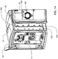
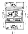
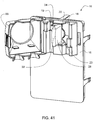
- a blood circuit assembly for a dialysis unit comprising: an organizing tray having a pair of handles arranged for gripping by a user for installing the blood circuit assembly on a dialysis unit; a pair of pneumatic pumps mounted to the organizing tray for circulating blood received from a patient through a circuit including a dialyzer unit and returned to the patient; an air trap mounted to the organizing tray arranged to remove air from blood circulating in the circuit; a pair of dialyzer connections arranged to connect to the inlet and outlet of a dialyzer unit, and a pair of blood line connectors, one inlet blood line connector for receiving blood from the patient and providing blood to the pneumatic pumps and the other outlet blood line connector for returning blood to the patient.
- the inlet blood line connector is connected to an inlet for the pump cassette, an outlet for the pump cassette is connected to a dialyzer inlet connector, a dialyzer outlet connector is connected to an inlet of the air trap, and an outlet of the air trap is connected to the outlet blood line connector.
- the inlet of the air trap may be located above the outlet of the air trap when the blood circuit assembly is mounted to a dialysis unit, e.g., to aid in trapping of air circulating in the circuit during treatment.
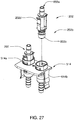
- the blood line connectors may be arranged for a threaded luer-type connection to a patient access, as well as be arranged for a press-in type connection to the dialysis unit.
- Such an arrangement may make it easier for an operator to connect the blood line connectors to the dialysis unit after treatment (e.g., for later disinfection and/or priming of the blood circuit) while allowing the connectors to engage with standard luer-type connectors at a patient blood access.
- the organizing tray may include circuit tube engagement members having a hole or slot through which a respective circuit tube passes.
- the engagement members may engage with the respective circuit tube to allow the circuit tube to be pulled and stretched for engagement with an occluder of the dialysis unit.
- the circuit tubes of the blood circuit assembly may include silicone tubing that has to be stretched (and thereby reduced in diameter) to engage with an occluder.
- the circuit tube engagement members may resist the pull of an operator on the tubes, allowing the tubes to be stretched and placed in engagement with the occluder.
- a method for replacing a blood circuit assembly including grasping the pair of handles on the organizing tray that is mounted to a dialysis unit, disengaging locking tabs of the dialysis unit from the blood circuit assembly to free the blood circuit assembly from the dialysis unit, and pulling on the handles on the organizing tray of the blood circuit assembly to remove the blood circuit assembly from the dialysis unit.
- Disengagement of the locking tabs may be performed by flexing the locking tabs away from each other such that each locking tab is moved toward a nearest one of the handles.
- a replacement blood circuit assembly After removal of the blood circuit assembly, a replacement blood circuit assembly may be provided, openings in the organizing tray of the replacement blood circuit assembly may be aligned with the locking tabs so that each locking tab is received into a respective opening, and the organizing tray may be pushed relative to the dialysis unit such that the locking tabs engage with the replacement blood circuit assembly to mount the replacement blood circuit assembly to the dialysis unit. Mounting the replacement blood circuit assembly may also involve connecting control ports on the dialysis unit to mating ports on the assembly so that fluid control signals may be provided for pumps and valves of the blood circuit assembly. Other blood circuit connections may be made, such as inlet and outlet connections for the dialyzer, and the blood line connectors may be connected to receive dialysate into the blood circuit
- Embodiments described herein generally relate to hemodialysis and similar dialysis systems. Illustrative embodiments described herein involve, in some cases, interrelated products, alternative solutions to a particular problem, and/or a plurality of different uses of one or more systems and/or articles. Although the various systems and methods described herein are described in relation to hemodialysis, it should be understood that the various systems and method described herein are applicable to other dialysis systems and/or in any extracorporeal system able to treat blood or other bodily fluids, such as hemofiltration, hemodiafiltration, etc.
- Embodiments described herein are generally directed to new systems for hemodialysis and the like, such as hemofiltration systems, hemodiafiltration systems, plasmapheresis systems, etc. Accordingly, although the various systems and methods described herein are described in relation to hemodialysis, it should be understood that the various systems and method described herein are applicable to other dialysis systems and/or in any extracorporeal system able to treat blood or other bodily fluids, such as plasma.
- a hemodialysis system typically includes a blood flow path and a dialysate flow path. It should be noted that within such flow paths, the flow of fluid is not necessarily linear, and there may be any number of "branches" within the flow path that a fluid can flow from an inlet of the flow path to an outlet of the flow path. Examples of such branching are discussed in detail below.
- blood flow path blood is drawn from a patient, and is passed through a dialyzer, before being returned to the patient.
- the blood is treated by the dialyzer, and waste molecules (e.g., urea, creatinine, etc.) and water are passed from the blood, through a semi-permeable membrane in the dialyzer, into a dialysate solution that passes through the dialyzer by the dialysate flow path.
- waste molecules e.g., urea, creatinine, etc.
- water are passed from the blood, through a semi-permeable membrane in the dialyzer, into a dialysate solution that passes through the dialyzer by the dialysate flow path.
- blood may be drawn from the patient from two lines (e.g., an arterial line and a venous line, i.e., "dual needle” flow), or in some cases, blood may be drawn from the patient and returned through the same or catheter needle (e.g., the two lines or lumens may both be present within the same needle, i.e., a form of "dual lumen" flow).
- a "Y" site or “T” site is used, where blood is drawn from the patient and returned to the patient through one patient connection having two branches (one being the fluid path for the drawn blood, the second the fluid path for the return blood, i.e., a form of "single needle” flow).
- the patient may be any subject in need of hemodialysis or similar treatments, including non-human subjects, such as dogs, cats, monkeys, and the like, as well as humans.
- the dialysate in some cases may be re- circulated in a "multi-pass" arrangement, which may be beneficial in capturing larger molecules having low mobility across the dialyzer.
- the dialysate is heated prior to treatment of the blood within the dialyzer using an appropriate heater, such as an electrical resistive heater.
- the dialysate may also be filtered to remove contaminants, infectious organisms, debris, and the like, for instance, using an ultrafilter.
- the ultrafilter may have a pore size chosen to prevent species such as these from passing therethrough. For instance, the pore size may be less than about 0.3 micrometers, less than about 0.2 micrometers, less than about 0.1 micrometers, or less than about 0.05 micrometers, etc.
- the dialysate is used to draw waste molecules (e.g., urea, creatinine, ions such as potassium, phosphate, etc.) and water from the blood into the dialysate through osmosis or convective transport, and dialysate solutions are well-known to those of ordinary skill in the art.
- waste molecules e.g., urea, creatinine, ions such as potassium, phosphate, etc.
- ions such as potassium, phosphate, etc.
- the dialysate need not be prepared at the same rate that the dialysate is used to treat the blood.
- the dialysate can be made concurrently or prior to dialysis, and stored within a dialysate storage vessel or the like.
- the dialysate and the blood typically are separated by a semipermeable membrane.
- the semipermeable membrane is formed from a polymer such as cellulose, polyarylethersulfone, polyamide, polyvinylpyrrolidone, polycarbonate, polyacrylonitrile, or the like, which allows the transport of ions or small molecules (e.g., urea, water, etc.), but does not allow bulk transport or convection during treatment of the blood.
- ions or small molecules e.g., urea, water, etc.
- larger molecules such as beta-2- microglobulin
- ions and molecules may pass through the dialyzer by convective flow if a hydrostatic pressure difference exists across the semi-permeable membrane.
- fluid means anything having fluidic properties, including but not limited to, gases such as air, and liquids such as water, aqueous solution, blood, dialysate, etc.
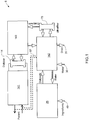
- FIG. 1 shows a schematic block diagram of fluid circuitry for a hemodialysis system.
- the dialysis system 5 includes a blood flow circuit 141 that draws blood from a patient, passes the blood through a dialyzer 14, and returns the treated blood to the patient.
- a balancing circuit or an internal dialysate circuit 143 receives dialysate from an ultrafilter 73, passes the dialysate through the dialyzer 14, and receives used dialysate from the dialyzer 14.
- a directing circuit or an external dialysate circuit 142 provides fresh dialysate to the ultrafilter 73, and receives used dialysate from the internal dialysate circuit 143 (which may be directed to a drain 31).
- the directing circuit 142 can also receive water from a water supply 30 and pass it to a mixing circuit 25.
- the mixing circuit 25 forms dialysate using water from the directing circuit 142 and reagent ingredients 49, such as citric acid, salt and a bicarbonate, that may be received from a renewable source.
- the mixing circuit 25 may prepare dialysate, for example, on an as-needed basis, during and/or in advance of dialysis. New dialysate prepared by the mixing circuit 25 may be provided to the directing circuit 142, which may provide the dialysate to the ultrafilter 73, as described above.
- the directing circuit 142 may include a heater to heat the dialysate to a suitable temperature and/or to heat fluid in the system for disinfection.
- Conduits 67 (shown in dotted line) may be connected between the blood flow circuit 141 and the directing circuit 142, e.g., for disinfection of the hemodialysis system.
- FIG. 2 is a schematic diagram showing a more detailed circuit arrangement for the dialysis system 5 shown in FIG. 1 . It should be understood, of course, that FIG. 2 is only one possible example of the general hemodialysis system of FIG. 1 , and in other embodiments, other fluid circuits, modules, flow paths, layouts, etc. are possible.
- the blood flow circuit 141 includes an anticoagulant supply 11 and a blood flow pump 13 which pumps blood from a patient through a dialyzer 14 and returns the blood to the patient.
- the anticoagulant supply 11 although shown in the path of blood flowing towards the dialyzer, may be instead located in another suitable location, e.g., any location upstream or downstream from blood flow pump 13.
- the balancing circuit 143 includes two dialysate pumps 15, which pump dialysate into the dialyzer 14, and a bypass pump 35. The flow of blood through the blood flow circuit 141 in some cases, is synchronized with the flow of dialysate in the dialysate flow path.
- FIG. 3 shows a close-up view of the blood flow circuit 141 in this illustrative embodiment.
- blood flows from a patient through arterial line 203 via blood flow pump 13 to the dialyzer 14 (the direction of flow during normal dialysis is indicated by arrows 205; in some modes of operation, however, the flow may be in different directions, as discussed below).
- an anticoagulant may be introduced into the blood via anticoagulant pump 80 from an anticoagulant supply.
- the blood After passing through dialyzer 14 and undergoing dialysis, the blood returns to the patient through venous line 204, optionally passing through an air trap and/or a blood sample port 19.
- the pump 13 may include, for instance, pumps 23 that are actuated by a control fluid.
- the blood flow pump 13 may comprise two (or more) pod pumps 23.
- Each pod pump in this particular example, may include a rigid chamber with a flexible diaphragm or membrane dividing each chamber into a pumping compartment and control compartment. There may be four entry/exit valves for these compartments, two for the pumping compartment and two for the control compartment.
- the valves for the control compartment of the chambers may be two-way proportional valves, one connected to a first control fluid source (e.g., a high pressure air source), and the other connected to a second control fluid source (e.g., a low pressure air source) or a vacuum source.
- the fluid valves can be opened and closed to direct fluid flow when the pod pumps 23 are operating.
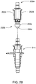
- FIG. 29 shows one example of a reciprocating positive-displacement pump 625 that can be used in embodiments of the present disclosure.
- the reciprocating positive- displacement pump 625 is essentially a self-contained unit (which may be referred to hereinafter as a "pod") that may be used as a component of a larger pumping system.
- the reciprocating positive-displacement pump 625 includes a "top” portion (also referred to as the "pumping chamber wall”) 631 and a "bottom” portion (also referred to as the "control chamber wall”) 632 that are coupled together at pod wall 630, for example, by ultrasonic welding or other technique.
- each of the portions 631 and 632 has a rigid interior surface that is preferably (although not necessarily) hemispherical, such that the pod has an interior cavity that is preferably (although not necessarily) spherical.
- control chamber wall 632 is a unitary structure while the pumping chamber wall 631 is formed from two halves that are coupled together along perimeter 2052, for example, by ultrasonic welding or other technique (which facilitates assembly of the integral valves, discussed below).
- this design may allow for minimum flash or burrs, which is more likely to present a gentler pumping environment. This example may be advantageous for use with fluids vulnerable to shear forces, and where flash or burrs therefore should be avoided.
- the application of negative pneumatic pressure to the pneumatic interface 638 tends to withdraw the membrane 633 toward the control chamber wall 632 so as to expand the pumping chamber and draw fluid into the pumping chamber through the inlet 634, while the application of positive pneumatic pressure tends to push the membrane 633 toward the pumping chamber wall 631 so as to collapse the pumping chamber and expel fluid in the pumping chamber through the outlet 637.
- the interior surfaces of the pumping chamber wall 631 and the control chamber wall 632 limit movement of the membrane 633 as it reciprocates back and forth.
- the interior surfaces of the pumping chamber wall 631 and the control chamber wall 632 are rigid, smooth, and approximately hemispherical.
- an alternative rigid limit structure - for example, a portion of a bezel used for providing pneumatic pressure and/or a set of ribs - may be used to limit the movement of the membrane as the pumping chamber approaches maximum value.
- the rigid limit structure - such as the rigid control chamber wall 632, a bezel, or a set of ribs - defines the shape of the membrane 633 when the pumping chamber is at its maximum value.
- the membrane 633 (when urged against the rigid limit structure) and the rigid interior surface of the pumping chamber wall 631 define a spheroid pumping-chamber volume when the pumping chamber volume is at a maximum.
- the membrane 633 moves from a position limited by the control-chamber wall 632 to a position limited by the pumping-chamber wall 631.
- the membrane and the pumping-chamber wall 631 define the maximum volume of the pumping chamber.
- the pumping chamber is at its minimum volume.
- the pumping-chamber wall 631 and the control-chamber wall 632 both have a hemispheroid shape so that the pumping chamber will have a spheroid shape when it is at its maximum volume. More preferably, the pumping-chamber wall 631 and the control-chamber wall 632 both have a hemispherical shape so that the pumping chamber will have a spherical shape when it is at its maximum volume.
- the orientations of the inlet 634 and outlet 637 - with each being substantially tangential to the interior surface of the pumping chamber wall 631 - also tend to improve circulation of fluid through the pumping chamber and reduce the likelihood of stagnant pockets of fluid forming. Additionally, compared to other volumetric shapes, the spherical shape (and spheroid shapes in general) tends to create less shear and turbulence as the fluid circulates into, through, and out of the pumping chamber.
- the pod pump components can be manufactured using any one of a number of methods of manufacturing, including but not limited to injection molding, compression molding, casting, thermoforming or machining. In some examples, where the pod pump chambers are machined, they can be fused together using mechanical fasteners or heat fused.
- the pump housing made from a thin film made of a material which includes, but is not limited to PETE, PETG, and PET. In these examples, the housing may be thermoformed, for example, vacuum or pressure formed, and the pump membrane is formed from a thin plastic film that can be heat sealed to the housing. In some examples, the pump housing is a multi-layer film. These examples are conducive to bonding the pump housing to another component.
- FIG. 30 is a sectional view of an alternative pod pump 2025 such as may be incorporated into a larger fluid-control cassette.
- the pod pump is formed from three rigid pieces, namely a "top” plate 2091, a middle plate 2092, and a “bottom” plate 2093 (it should be noted that the terms “top” and “bottom” are relative and are used here for convenience with reference to the orientation shown in FIG. 30 ).
- the top and bottom plates 2091 and 2093 may be flat on both sides, while the middle plate 2092 is provided with channels, indentations and holes to define the various fluid paths, chambers, and ports.
- the top and bottom plates 2091 and 2093 may include generally hemispheroid portions that together define a hemispheroid chamber.
- a membrane 2109 separates the central cavity of the pod pump into a chamber (the pumping chamber) that receives the fluid to be pumped and another chamber (the actuation chamber) for receiving the control gas that pneumatically actuates the pump.
- An inlet 2094 allows fluid to enter the pumping chamber, and an outlet 2095 allows fluid to exit the pumping chamber.
- the inlet 2094 and the outlet 2095 may be formed between middle plate 2092 and the bottom plate 2093.
- Pneumatic pressure is provided through a pneumatic port 2106 to either force, with positive gas pressure, the membrane 2109 against one wall of pod pump's cavity to minimize the pumping chamber's volume (as shown in FIG. 30 ), or to draw, with negative gas pressure, the membrane towards the other wall of the pod pump's cavity to maximize the pumping chamber's volume.
- FIG. 31 is a sectional view of a pneumatically controlled valve 2000 that may be used in embodiments of the above-mentioned cassette.
- Pneumatic pressure is provided through a pneumatic port 2096 to either force, with positive gas pressure, the membrane 2090 against a valve seat 2099 to close the valve, or to draw, with negative gas pressure, the membrane away from the valve seat to open the valve.
- a control gas chamber 2098 is defined by the membrane 2090, the top plate 2091, and the middle plate 2092.
- the middle plate 2092 has an indentation formed on it, into which the membrane 2090 is placed so as to form the control gas chamber 2098 on one side of the membrane and the valving chamber 2097 on the other side.
- the top plate 2091 may include additional material extending into control gas chamber 2098 so as to prevent the membrane 2090 from being urged too much in a direction away from the groove 2089, so as to prevent the membrane's thickened rim 2088 from popping out of the groove 2089.
- the pod pump is spheroid shaped
- the pod pump can be any shape desired, such as an ovoid shape.
- Many of the embodiments of the pod pumps will include a pump chamber, an actuation chamber, a diaphragm (or movable member), at least one actuation port and at least one inlet/outlet port.
- the pod pump includes an inlet and an outlet port.
- actuation chamber cover 3304 and mid plate 3306 are made of plastic, but in other embodiments may be made from other materials including but not limited to metal or glass.
- covers 3302 and 3304, and mid plate 3306 are made from polysulfone. In another exemplary pump, they are made from medical grade polycarbonate.
- the pump chamber cover 3302, actuation chamber cover 3304 and mid plate 3306 may be joined by laser welding or may be joined by various other methods as deemed appropriate for the chosen component materials and the desired pod pump use.
- joining possibilities include but are not limited to snap together tabs, press fit, snap fit, solvent bonding, heat welding, electromagnetic welding, resistance welding, RF welding, screws, bolts, ultrasonic welding, adhesive, clamping by components that neighbor the pump when in use or other joining methods commonly used in the art.
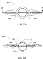
- FIGS. 33A and 33B one example of a pod pump 3400 is shown.
- inlet and outlet ports are located at opposite ends of the pump chamber 3406 and are interchangeable depending on the configuration of the pump or its intended use.
- the diaphragm 3408 is shown nearly fully extended into the pump chamber 3406.
- the inlet and outlet ports 3402 and 3404 may be partially or fully obscured by the diaphragm 3408 when fully actuated by fluid pressure in the actuation chamber 3410. Blocking of the inlet or outlet ports may serve to limit or switch the flow of subject fluid through the pump chamber 3406 as may be desired in certain applications.
- the pumping side of the diaphragm 3408 i.e., the side of the diaphragm 3408 that contacts the subject fluid, is smooth, which may provide different flow characteristics with some subject fluids or provide different contact between the diaphragm 3408 and pump chamber 3406 when reduction of flow through the inlet or outlet ports 3402 and 3404 is desired when the diaphragm is fully extended into the pump chamber 3406.
- the diaphragm has a variable cross-sectional thickness, as shown in FIG. 33B .
- Thinner, thicker or variable thickness diaphragms may be used to accommodate the strength, flexural and other properties of the chosen diaphragm materials.
- Thinner, thicker or variable diaphragm wall thickness may also be used to manage the diaphragm thereby encouraging it to flex more easily in some areas than in other areas, thereby aiding in the management of pumping action and flow of subject fluid in the pump chamber 3406.
- the diaphragm 3408 is shown having its thickest cross-sectional area closest to its center.
- the thickest and thinnest areas may be in any location on the diaphragm 3408.
- the thinner cross-section may be located near the center and the thicker cross-sections located closer to the perimeter of the diaphragm 3408. Still other configurations are possible.
- the pod pump is incorporated into a device which is then integrated or attached to a machine, device, or container.
- a cassette having integrated pod pumps, fluid paths, fluid ports, actuation ports and actuation fluid paths.
- FIGS. 34A-34C and 35A-35B Two examples of a cassette are described with respect to FIGS. 34A-34C and 35A-35B . It is understood that these are merely exemplary cassettes, and that many additional embodiments having different numbers and arrangements of pumps, valves and flow paths can be constructed using similar principles.
- FIGS. 34A-34C a pod pump cassette 4300 is shown.
- this pod pump cassette includes two pod pumps 4310.
- the pod pumps 4310 can be any type of pod pump, but in this exemplary cassette, the pod pumps 4310 are similar to the pod pump shown in FIGS. 32 and 33 .
- the cassette 4300 includes three plates, an actuation plate 4320, a mid plate 4330 and a pump chamber plate 4340.
- the actuation plate 4320 includes, for each pod pump 4310, a pod pump actuation chamber housing 4312 portion and two valves actuation housing 4314 portions.
- the valve actuation housing 4314 includes a valve actuation port 4316.
- the cassette 4300 in some examples, may contain additional ports and/or containers to or from which various fluids can be pumped.
- the mid plate 4330 includes, for each pod pump, a pump diaphragm 4332 and two valve diaphragms 4334.
- the valves are volcano or active valves actuated by a diaphragm 4334 which is actuated by a fluid, which in this cassette is pneumatic air.
- Also shown on this cassette 4300 are additional diaphragms in the mid plate 4330.
- each pod pump 4310 includes a pump chamber housing 4342 which includes an integral fluid path 4344.
- the pump chamber housing 4342 is in fluid connection with an exterior fluid path 4346.
- the three plates 4320, 4330, 4340 are laser welded together.
- various modes of attachment some of which are described above, may be used.
- FIG. 34B a cross sectional view of the cassette 4300 is shown.
- the volcano valves are shown including the valve diaphragms 4334, the valves actuation housing 4314 portions and the exterior fluid line 4346.
- the valves are actuated by pneumatic air through actuation ports 4318.
- an air filter 4350 and an additional fluid line 4352 may be included in the cassette.
- FIGS. 35A and 35B An alternate example of the cassette is shown in FIGS. 35A and 35B .
- the cassette 4400 includes greater than three portions.
- the portions include a mid plate 4410 with multiple covers 4412-4416 laser welded onto the mid plate. These multiple covers 4412-4416 are used rather than the pump plate shown in FIG. 34A as 4340.
- FIG. 35B the mid plate 4410 again is shown. However, in this cassette, multiple covers 4442-4444 are used rather than a single actuation plate as shown in FIG. 34A as 4320.
- FIGS. 35A-35C show one example; in other examples, the number of multiple covers may very.
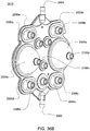
- the pump cassette 2015 includes a common inlet 2005 in fluid communication with pod pump 2025a via fluid paths 2007 and 2009 and with pod pump 2025b. via fluid paths 2008 and 2010.
- the pump cassette 2015 also includes a common outlet 2006 in fluid communication with pod pump 2025a via fluid paths 2011 and 2013 and with pod pump 2025b via fluid paths 2012 and 2014.
- pod pumps 2025a and 2025b draw fluid from the common inlet 2005 and pump fluid to the common outlet 2006.
- a phase relationship of 0° may be useful in some cases for single needle/single lumen flow or in other cases.
- the pod pumps will first fill from the needle, then deliver blood through the blood flow path and back to the patient using the same needle.
- running at phases between 0° and 180° can be used in some cases, to achieve a push/pull relationship (hemodiafiltration or continuous back flush) across the dialyzer.
- An anticoagulant pump 80 which can act as a metering chamber in some cases, can be used to control the flow of anticoagulant into the blood circuit.
- the anticoagulant pump 80 may be a pod pump or a membrane-based metering pump, and/or may be actuated by a control fluid, such as air.
- the anticoagulant pump 80 may include a rigid chamber with a flexible diaphragm dividing the chamber into a pumping compartment and a control compartment.
- One valve for the control compartment of the chamber may be connected to a first control fluid source (e.g., a high pressure air source), and the other valve connected to a second control fluid source (e.g., a low pressure air source) or a vacuum source.
- a first control fluid source e.g., a high pressure air source
- a second control fluid source e.g., a low pressure air source
- Valves for the pumping compartment of the chamber can be opened and closed in coordination with the control compartment, thus controlling the flow of anticoagulant into the blood.
- air provided through a filter 81 may also be introduced into the blood flow path by the anticoagulant pump 80, e.g., to provide air into the vial 11 after or before anticoagulant is withdrawn from the vial.
- Coupled to refers to the chambers or components being attached to, or interconnected with, another component of the pumping system, such that the other component is able to exert a force on an external surface of the chamber or component to which it is coupled.
- Control chamber 110 includes a pressure measuring component 122 for determining the pressure of the measurement gas within the control chamber.
- a "pressure measuring component” as used herein refers to a device that is able to convert a fluid pressure into a measurable signal or parameter. Pressure measuring components that may be useful in this example include but are not limited to: transducers; pressure gauges; manometers; piezoresistive elements; and others as apparent to those of ordinary skill in the art.
- Control chamber 110 of pumping system 100 may also include a vent line 124 including a vent valve 126 therein.
- Control chamber 110 is connected in fluid communication with a variable volume cylinder 128 via a measurement gas inlet line 130.
- Variable volume cylinder 128 which includes a piston 132 therein which is moved and actuated by motor 133 for compressing, or expanding the volume of the measurement gas contained within the system.
- Pumping system 100 also preferably contains a processor 134 which is in electrical communication with the various valves, pressure transducers, motors, etc. of the system and is preferably configured to control such components according to a desired operating sequence or protocol.
- a processor being "configured" to perform certain tasks herein refers to such processor containing appropriate circuitry, programming, computer memory, electrical connections, and the like to perform a specified task.
- the processor may be implemented as a standard microprocessor with appropriate software, custom designed hardware, or any combination thereof.
- pump chamber 108 is oriented in an essentially vertical configuration during operation such that inlet line 114 is disposed above outlet line 118.
- the above-described orientation is advantageous for preventing any gas which may be present in pump chamber 108 during operation from being pumped from the pump chamber to a downstream destination through outlet line 118. Instead, any gas contained within pump chamber 108 will tend to rise towards the top of the pump chamber, for example the region adjacent to inlet port 136, and will be detected by the system, as described in more detail below, before being pumped from the pump chamber.
- pump chamber 108 includes the novel inclusion of a plurality of spacers 138 included therein.
- the spacers 138 function to prevent flexible membrane 112 from contacting an inner surface 140 of the pump chamber when the liquid contained within pump chamber 108 is being pumped through outlet line 118.
- dashed line 442 the maximum displacement of flexible membrane 112 which is permitted by spacers 138 is shown in FIG. 37 by dashed line 442. It can be seen that even with flexible membrane 112 at its maximum displacement into pump chamber 108, as defined by dashed line 442, spacers 138 create a dead space 144 to contain any gas which may be present in pump chamber 108, thus inhibiting the gas from being pumped through the pump chamber.
- Spacers 138 in combination with the vertical orientation of pump chamber 108, also serve to assist any gas present in pump chamber 108 to rise to the top of the pump chamber so that it may more easily be purged from the pump chamber, as described in more detail below.
- Pump chamber 108 of pumping system 100 is essentially defined by a substantially rigid wall 145 (e.g., made of a rigid plastic such as a polyacrylate) having a flexible membrane 112 disposed over the wall, thus forming a volumetric chamber.
- a substantially rigid wall 145 e.g., made of a rigid plastic such as a polyacrylate
- a flexible membrane 112 disposed over the wall, thus forming a volumetric chamber.
- the pump chamber preferably includes a movable surface which comprises an elastic membrane.
- the restoring force of the elastic membrane when stretched or displaced from a relaxed equilibrium condition, enables the pressure on each side of the membrane (i.e. in the pump chamber and control chamber) to be different, where the degree of difference in the pressures, and the resistance to further displacement/stretching (stress/elastic energy stored in the membrane), is a function of the degree of stretch or displacement from the relaxed equilibrium condition of the membrane.
- the measurement gas pressures applied to the elastic membrane during the determination of pump/control chamber volumes at the first and second conditions of applied force for detecting air/gas in the pump chamber discussed above tend to stretch the elastic membrane (if air/gas is present in the pump chamber), from its equilibrium configuration before the pressure is applied, by a different extent for each condition, so that the stress in the membrane and its resistance to further displacement in response to a given level of applied pressure will be different for the first and second condition (or in other words, the force/displacement response of the elastic membrane for the first and second conditions will be asymmetrical).
- the difference in the pressure in the control chamber versus the pressure in the pump chamber, at an equilibrium condition will be different for the first condition of applied pressure versus the second condition of applied pressure.
- the different level of stress and strain of the elastic membrane during measurements of pump/control volume determined at the first and second conditions above create, at least in part, deviations in the pressure-volume behavior of the measurement gas from that predicted for each condition by the equation of state, which deviations can create and/or enhance a difference in the volume of the pump/control chamber determined for each condition by using the equation of state.
- One way to achieve or enhance such asymmetry in the response of the elastic membrane to the applied measurement gas pressures utilized during volume determinations for gas detection is to perform the volume determination steps when the pump chamber flexible elastic membrane has already been stretched, from the configuration it has at a relaxed equilibrium condition, with essentially equal fluid pressures on each side of the membrane, before the application of pressurized measurement gas to the membrane for the purpose of volume measurements.
- This can be accomplished, for example, by performing the volume determinations related to air/gas detection after filling the pump chamber with sufficient liquid so that the elastic membrane is at least somewhat stretched, and preferably substantially stretched, by displacement of the membrane in the direction of the control chamber, and by using a positive measurement gas pressure during volume measurement at the first condition and a negative measurement gas pressure during volume measurement at the second condition (or vice- versa.
- the desired asymmetry in the response of the elastic membrane during volume determinations involved in air/gas detection could also be achieved by utilizing levels of measurements gas pressures applied to the elastic membrane for volumetric determinations performed at the first and second conditions of measurement that are selected to impart a different, and preferably substantially different degree of elastic stretch to the membrane.
- preferred examples of pump chambers for use when utilizing an equation of state based procedure for calculating pump/control chamber volumes include a moveable surface at least partially comprised of an elastic membrane, in alternative embodiments, non-elastic movable surfaces could potentially be used, as long as the measurement fluid pressures applied to the surface during volume measurement at the first condition and second condition create different levels of stress in the surface and differences in the equilibrium pressures within the control and pump chamber.
- Such examples could, for example, utilize a non-elastic movable surface or flaccid membrane, where measurement fluid pressures applied during the first condition of volume determinations tend to move the surface/membrane (if a gas is present in the pump chamber) to its maximum allowed displacement so that the surface is no longer free to move in response to the applied force, a stress is created in the surface/membrane, and a pressure difference exists between the pump and control chambers.
- Measurement of volume at a second condition for such examples could apply a different measurement fluid pressure to the surface, the pressure tending to move the surface/membrane (if a gas is present in the pump chamber) to reduce or substantially eliminate the stress within the surface/membrane so that at equilibrium, the difference in pressure in the pump and control chambers is reduced or essentially eliminated.
- step 1 involves initializing the system so that all valves are closed and piston 132 and flexible membrane 112 are in the positions described above.
- step 2 involves filling the pump chamber 108 with a liquid to be pumped. The step involves first opening inlet valve 116, then actuating motor 133 so as to move piston 132 to position 3 Shown in FIG.
- Step 3 (474) of the exemplary pumping cycle involves a series of sub, and for detecting the presence of any gas contained within pump chamber 108. Step 3 (474) is described in greater detail in FIG. 38B .
- step 4 (208) of the pumping cycle involves delivering the liquid contained in pump chamber 108. First, outlet valve 120 is opened. Motor 134 is then actuated to move piston 132 from position 3 to position 1, thereby delivering a volume of fluid .DELTA.V. Outlet valve 120 is then closed in order to isolate pump chamber 108.
- the volume of pump chamber 108 after step 4 (208) may be determined, for example, by repeating substeps 1-4 (476, 478, 480, 482) of the volume calculation and air detection subcycle of FIG. 38B .
- the volume delivered for the above described pump stroke can be determined by taking a difference in the volume of pump chamber 108 determined in step 3 (474) and in step 5 (210).
- the entire pump cycle of FIG. 38 A may be repeated.
- the volume of fluid contained in pump chamber 108 is then determined in substeps 4 (482), with the pump chamber at this first conditions, using an appropriate equation of state for the measurement fluid being utilized.
- a measurement gas such as air
- Equation 1 assumes that any temperatures changes or differences caused by changing the volume of measurement gas are minimal and that the system is essentially isothermal. It will be appreciated that for systems where temperature changes may be significant, the temperature dependence of the measurement fluid, as defined by the equation of state being used, may be incorporated into the volume calculation of substeps 4 (482) in a straightforward fashion, as apparent to those of ordinary skill in the art.
- V.sub.F in equation 1 refers to the internal volume of pump chamber 108 and V.sub.T refers to the known total volume of the system including pump chamber 108, control chamber 110, and the volumes contained within measurement fluid inlet line 130 and cylinder 128.
- the blood flow circuit 141 may also include an air trap 19 to remove air bubbles that may be present within the blood flow path.
- the air trap 19 is able to separate any air that may be present from the blood due to gravity, and /or may include a port for sampling blood.
- FIG. 4 shows a close-up view of the balancing circuit 143 in the FIG. 2 dialysis system.
- dialysate flows from the optional ultrafilter 73 into a dialysate pump 15.
- the dialysate pump 15 includes two pod pumps 161, 162, two balancing chambers 341, 342, and a pump 35 for bypassing the balancing chambers 341, 342.
- the balancing chambers 341, 342 may be constructed such that they are formed from at rigid chamber with a flexible diaphragm dividing the chamber into two separate fluid compartment, so that entry of fluid into one compartment can be used to force fluid out of the other compartment and vice versa.
- An exemplary balancing pod is shown in FIG. 39 .
- inlets 1102 and outlets 1104 for each chamber are shown to be on the same side, in other examples, the inlets 1102 and outlets 1104 for each chamber are on different sides. Furthermore, the inlets 1102 and outlets 1104 can be on either side, depending on the flow path in which the balancing pod is integrated.
- Pod pump 161 forces used dialysate contained within the pod pump (from the previous step) into balancing chamber 341, since valves 232 and 211 are closed and valve 223 is open. This causes fresh dialysate container within balancing chamber 341 to be directed into the dialyzer 14 (since valve 241 is now open while valve 212 is now closed). At the end of this step, pod pump 162 and balancing chamber 342 have filled with dialysate. This puts the state of the system back into the configuration at the beginning of this description, and the cycle is thus able to repeat, ensuring a constant flow of dialysate to and from the dialyzer 14.
- the fluid e.g. pneumatic pressures on the control side of the balancing chamber valves are monitored to ensure they are functioning (e.g., opening and closing) properly.
- each balancing chamber one volume is occupied by fresh dialysate heading towards the dialyzer and the other volume is occupied by used dialysate heading from the dialyzer.
- the volumes of dialysate entering and leaving the dialyzer are kept substantially equal.
- the balancing circuit pump diaphragm When running in such a balanced mode, if there is no delivery pressure from the blood flow pump, the balancing circuit pump diaphragm will push fluid across the dialyzer into the blood and the alternate pod of the balancing circuit will not completely fill. For this reason, in preferred examples, the blood flow pump reports when it is actively delivering a stroke. When the blood flow pump is delivering a stroke the inside dialysate pump operates. When the blood flow pump is not delivering blood, the valves that control the flow from the dialyzer to the inside dialysate pumps (and other balancing valves ganged together with these valves, as previously discussed) may be closed to prevent any fluid transfer from occurring from the dialysate side to the blood side.
- the inside dialysate pump fill pressure can be set to a minimal positive value to ensure that the pump operates above atmosphere at minimal impendance.
- the inside dialysate pump delivery pressure can be set to the blood flow pump pressure to generally match pressures on either side of the dialyzer, minimizing flow across the dialyzer during delivery strokes of the inside dialysate pump.
- One method to control the pressure saturation limits would be to limit the desired flow rate to the slowest of the fill and deliver strokes. Although this would result in slower blood delivery flow rates, the flow rate would still be known and would be more continuous, which would allow for more accurate and continuous dialysate flow rates.
- Another method to make the blood flow rate more continuous in single needle operation would be to use maximum pressures to fill the pods so the fill time would be minimized.
- the desized deliver time could then be set to be the total desired stroke time minus the time that the fill stroke took.
- the dialysate flow rate may have to be adjusted upward during blood delivery to the dialyzer to make up for the time that the dialysate pump is stopped when the blood flow pump is filling. If this is done with the correct timing, an average dialysate flow rate taken over several strokes can still match the desired dialysate flow rate.
- FIG. 5 shows a close up of the directing circuit 142 in the FIG. 2 dialysis system.
- the directing circuit 142 can provide dialysate from a dialysate tank 169 via a dialysate pump 159 to a heater 72 and the ultrafilter 73.
- the heater 72 may be used to warm the dialysate to body temperature, and/or a temperature such that the blood in the blood flow circuit is heated by the dialysate, and the blood returning to the patient is at body temperature or higher.
- the heater 72 may be connected to a control system such that dialysate that is incorrectly heated (i.e., the dialysate is too hot or too cold) may be recycled (e.g., back to the dialysate tank 169) or sent to drain instead of being passed to the dialyzer.
- the heater 72 may also be used, in some cases, for disinfection or sterilization purposes. For instance, water may be passed through the hemodialysis system and heated using the heater such that the water is heated to a temperature able to cause disinfection or sterilization to occur, e.g., temperature of at least about 70°C, at least about 80°C, at least about 90°C, at least about 100°C, at least about 110°C, etc.
- the flow of dialysate through the directing circuit 142 may be controlled (at least in part) by operation of the dialysate pump 159.
- the dialysate pump 159 may control flow through the balancing circuit 143. For instance, as discussed above, fresh dialysate from the directing circuit 142 flows into balancing chambers 341 and 342 of balancing circuit. 143.
- the dialysate pump 159 may be used as a driving force to cause the fresh dialysate to flow into these balancing chambers.
- dialysate pump 159 includes a pod pump, e.g., similar to those described above.
- the dialysate may also be faltered to removed contaminants, infectious organisms, pathogens, pyrogens, debris, and the like, for instance, using an ultrafilter 73.
- the ultrafilter 73 may be positioned in any suitable location in the dialysate flow path, for instance, between the directing circuit and the balancing circuit, e.g., as shown, and/or the ultrafilter 73 may be incorporated into the directing circuit or the balancing circuit. If an ultrafilter is used, its pore size may be chosen to prevent species such as these from passing through the filter.
- Flow from the filter 73 may also be monitored for several reasons, e.g., using temperature sensors (e.g., sensors 251 and 252), conductivity sensors (for confirming dialysate concentration, e.g., sensor 253), or the like.
- temperature sensors e.g., sensors 251 and 252
- conductivity sensors for confirming dialysate concentration, e.g., sensor 253
- a sensing probe 6000 and a thermal well 5100 are shown coupled and outside of a fluid line.
- the thermal well 5100 can be in a fluid line, a protective sleeve, any disposable, machine chamber, cassette or container. However, for purposes of this description of the illustrated example, the thermal well 5100 is taken to be anywhere where it is used to determine thermal and/or conductive properties of a subject media.
- the ultrafilter and the dialyzer may provide redundant screening methods for the removal of contaminants, infectious organisms, pathogens, pyrogens, debris, and the like. Accordingly, any contaminant would have to pass through both the ultrafilter and the dialyzer before reaching a patient's blood. Even in the event that either the ultrafilter or dialyzer integrity fails, the other may still be able to maintain dialysate sterility and prevent contaminants from reaching the patient's blood.
- FIG. 7 shows a perspective view of a hemodialysis system 5 that incorporates various examples from the present teaching.
- the system 5 includes a dialysis unit 51 and a power unit module 52 that are shown joined together.
- the dialysis unit 51 has a housing that contains suitable components for performing hemodialysis, such as a dialyzer, one or more pumps to circulate blood through the dialyzer, a source of dialysate, and one or more pumps to circulate the dialysate through the dialyzer.
- the dialysis unit 51 may include the mixing circuit 25, blood flow circuit 141, the balancing circuit 143 and the directing circuit 142 as described above.
- the power unit 52 may be selectively connectable to the dialysis unit 51, e.g., to allow different power units 52 to be interchanged.
- the dialysis unit 51 may be arranged to work with different types of power units 52, such as power units 52 that use electrical power to generate the pneumatic power supply, as well as power units 52 that use stored pneumatic power (e.g., pressurized air stored in one or more high pressure tanks).
- a power unit 52 may be interchanged for another unit 52, in case of failure or other requirements. For example, it may be desired to use the system 5 in an area where noise generation is unacceptable, such as when nearby people are sleeping.
- the system 5 may include a "cold" section (which is not heated), and a “hot” section, portions of which may be heated, e.g., for disinfection purposes.
- the cold section may be insulated from the hot section through insulation.
- the insulation may be molded foam insulation, but in other systems can be any type of insulation, including but not limited to a spray insulation, an air space, insulation cut from sheets, etc.
- the cold section includes a circulation system, e.g., a fan and/or a grid to allow air to flow in and out of the cold box.
- the insulation may be extended to cover access points to the "hot” section, e.g., doors, ports, gaskets, and the like. For instance, when the "hot" section is sealed, the insulation may completely surround the "hot” section in some cases.
- Non-limiting examples of components that may be present within the "cold” section include power supplies, electronic, power cables, pneumatic controls, or the like. In some cases, at least some of the fluids going to and from the "hot” section may pass through the “could” section; however, in other cases, the fluids may pass to the "hot” section without passing through the "cold” section.
- the dialysis unit 51 housing may include vertical side-by-side doors that can be opened to expose all mechanical interface points for blood flow circuitry and connections for dialysate circuitry, i.e., all connection points for patient blood connections and acid/bicarbonate connections, that must be made by a user to use the dialysis unit 51.
- FIG. 9 shows a front view of the dialysis unit 51 with the vertical side-by-side doors 53 in a closed state.
- the doors 53 may block access to connection points for patient blood connections and acid/bicarbonate connections as well as seal the interior of the unit housing so as to allow heat retention suitable for disinfection.
- the seal provided by the doors 53 may be hermetic, preventing or substantially resisting any air exchange between the housing interior and an exterior environment, or may be of a somewhat lesser quality yet still allow for disinfection.
- FIGs. 10-13 show the doors 53 in a first state of opening. In this state, the doors 53 expose all user-made connections for the blood circuit connections and for the dialyzer circuitry, including the dialyzer 14 itself and for reagent materials, such as consumable acid/bicarbonate materials. This position also exposes several other features, such as holders 531 for an acid/bicarbonate container (not shown) and hooks 532 that may be used to hold any suitable item, such as the control interface 55, which may be hung by its handle on one of the hooks 532. (See also FIG.
- the holders 531 may be folded down from their position shown in the figures (i.e., folded up and into recesses in the doors 53) so as to extend horizontally from the doors 53.
- the holders 531 have a "C" shaped receiving section to receive and hold an acid/bicarbonate container, but of course could be shaped or otherwise arranged in any suitable way.
- FIGs. 14-16 show the doors 53 in a second state of opening in which a hinge plate 533 for each door 53 is pivoted outward and away from the dialysis unit housing 51.
- the hinge plates 533 which in this example extend vertically along almost the entire height of the dialysis unit housing 51, are pivotally attached to the doors 53 at a first, outer end, and are pivotally attached at a second inner end to the dialysis unit housing 51.
- each plate 533 may include two or more portions that are vertically separated from each other, etc.
- Magnets 534 attached to the hinge plates 533 may interact with corresponding magnets (or other suitable components, such as a steel elements) attached to the dialysis unit housing 51 so as to attract the hinge plates 533 toward the dialysis unit housing 51, thus tending to keep the hinge plates 533 in the position shown in FIGs. 10-13 .
- the doors 53 in this example also include magnets attached near the hinge plates 533 so that when the doors 53 are opened to the first state as shown in FIGs 10-13 , the magnets interact with corresponding magnets in the hinge plates 533 to help keep the doors 53 in an open position relative to the hinge plate 533. These magnets will also help maintain the relative position of the doors 53 and the hinge plates 533 when the hinge plates 533 are opened to the second state shown in FIGs. 13-16 .
- the hinge connection between the doors 53 and the hinge plates 533 and/or the connection between the hinge plates 533 and the housing 51 may include a detent arrangement that serves to resiliently hold the door 53 or hinge plate 533 in a particular position relative to the other part (the hinge plate or housing, respectively).
- one or more springs may be used to help maintain the doors 53 in an open position relative to the hinge plates 533.
- the hinge plates 533 may have a friction or interference fit with a portion of the housing 51 that tends to maintain the hinge plates 533 in the closed position (adjacent the housing). Accordingly, a retainer member that functions to help maintain a door 53 in a particular position relative to its hinge plate 533, and/or that functions to help maintain a hinge plate 533 in a particular position relative to the housing 51, may take any one of a number of possible arrangements.
- opening of the doors to the dialysis unit housing may reveal all of the user-made connections for blood circuit connections and dialysate fluidic connections needed for operation of the system 5.
- a front panel 511 of the dialysis unit 51 may be exposed.
- the front panel 51 1 carries several items or connection points that must be accessed by a user.
- the dialyzers 14, which must be periodically replaced is mounted to the front panel 511. The dialyzers 14 must be connected not only to the blood flow circuit 141, but also the balancing circuit 143.
- connection point 512 for an acid/bicarbonate source 49 is located at a lower end of the front panel 51 1. It is at this connection point 512 that a user may connect a source of consumable reagent ingredients 49 used by the dialysis unit 51 in making dialysate.
- An occluder 513 is also mounted on the front panel 511. The occluder 513 receives tubes of the blood flow circuit and controls the open/closed state of the tubes based on system operation. In short, the occluder 513 allows flow through the arterial and venous lines of the blood flow circuit unless there is a system problem, such as a leak, pump failure, overpressure situation, etc.
- occluder 10 includes a base 16 and a pathway 18 for receiving tubing.
- pathway 18 is an indentation within base 16 shaped for receiving tubing.
- pathway 18 may be defined on base 16 in other ways, for example, by one or more ridges on the surface of base 16, by fasteners, loops, or rings on the surface of base 16, or the like.
- pathway 18 is shown as being substantially straight in this figure, in other embodiments, pathway 18 may be curved in some fashion. In some cases, the pathway may be designed to be slightly smaller than the tubing it is designed to carry, thus requiring some force and/or deformation of the tubing in order for it to be properly positioned within the pathway.
- the tubing may be bendable or flexible, for example, so that the tubing can be at least partially collapsed when occluding element 24 pushes into the tubing.
- the tube may be formed from materials such as silicone, nylon, rubber, polyvinyl chloride, polyurethane, polyethylene, or the like.
- the tubing is biocompatible.
- the tubing may be used, for example, to transport blood or other substances to or from a subject, e.g., as part of a dialysis machine or other medical infusion system.
- an occluding member 20 Positioned on base 16 is an occluding member 20 that is rotationally moveable about a pivot 22.
- the occluding member may rotate completely around the pivot, or in some cases, the occluding member can rotate only partially around pivot 22.
- Pivot 22 may be immobilized with respect to base 16.
- pivot 22 may be a screw or a rod, or a similar structure, that is affixed within base 16.
- Occluding member 20 may be constructed such that when it is rotated around pivot 22, occluding element 24 can enter and at least partially obstruct pathway 18. Fluid flowing within tubing contained within pathway 18 may thus be partially or completely inhibited from flowing past occluding element 24.
- occluding member 20 when occluding member 20 is in a second position, occluding element 24 does not enter into pathway 18, and thus fluid contained within a tubing in pathway 18 is not obstructed by oc
- occluding member 20 may be in one of two positions. In some cases, however, the occluding member may be positioned in more than two positions. For instance, occluding member 20 may contain more that one occluding element, which may each enter into or at least partially obstruct pathway 18 and/or other pathways present within base 16, or occluding member 20 may be constructed to be positioned in different positions, some of which may cause occluding element 24 to be present within pathway 18 to various degrees, thereby causing occlusion of fluid flow to varying degrees.
- FIG. 17 does not show the arterial and venous lines 203, 204 for the blood flow circuit 141 because, in this example, the blood flow circuit 141 is formed as a blood circuit assembly that is removable from the front panel 511 of the dialysis unit 51, and the blood circuit assembly is not mounted on the front panel 511 in FIG. 17 .
- FIG. 18 shows a front view of the blood circuit assembly 17, which is an embodiment of the present invention along with the dialyzer 14.
- the blood circuit assembly 17 includes various components discussed above, for example with reference to FIG. 3 , that are mounted to a blood circuit organizing tray 171.
- the arterial and venous lines 203 and 204 are terminated with blood line connectors that may be arranged to provide a plug-in or press-in connection with the blood line connection points 514 as well as provide a screw-type connection used with standard patient access points (e.g., luer type patient access connectors).
- the arterial line 203 leads to an inlet at the top of the blood pump 13, which includes two pod pumps 23, valves and other components for controlling blood flow.
- an air filter 81 Associated with the blood pump 13 are an air filter 81, an anticoagulant pump 80 (not shown), and an anticoagulant supply 11 (such as a vial of heparin).
- a second port 902 pushes air to the spike/source container, and also draws liquid from the source container 1202, which is then pushed by the metering pump 830 to the fluid line at point 826, where it enters the blood flow path of the blood pump cassette 1200.
- Valves 832, 834 and 836 are actuated in the proper order to ensure that the proper sequence of fluid withdrawal from source container 1202 and infusion into the blood path of the cassette occurs, followed by periodic air injection from air vent 906 into source container 1202 for purposes of pressure equalization within the container.
- the air trap 19 may be placed in the blood flow path after the blood exits the dialyzer and before it is returned to the patient.
- the air trap 19 can have a spherical or spheroid-shape container (i.e., a container having an approximately spherical inner wall), and have its inlet port located near the top and offset from the vertical axis of the container, and an outlet at a bottom of the container.
- the vertical axis of the container is arranged in a vertical direction passing through the top and bottom "poles" of the approximately spherical container.
- blood is introduced into the container in a direction that is approximately perpendicular to the vertical axis of the container and that is approximately tangential to the spherical inner wall of the container.
- the curved shape of the inside wall of the trap can thus direct the blood to circulate along the inside wall as the blood gravitates to the bottom of the container (e.g., in a spiral like fashion), facilitating the removal of air bubbles from the blood.
- a self-sealing port such as a self-sealing stopper with a split septum or membrane, or another arrangement, may be located at the top of the trap, allowing the withdrawal of air from the container (e.g., by syringe).
- the blood-side surface of the self-sealing membrane can be situated nearly flush with the top of the interior of the trap, in order to facilitate cleaning of the self-sealing port during disinfection, e.g., by reversing flow through the air trap using a dialysate or other cleaning fluid.
- FIG. 19 shows the organizing tray 171 for the blood circuit assembly 17 without the various blood circuit assembly 17 components mounted.
- the organizing tray 171 includes handles 172 (in this embodiment, finger pulls) that a user can grip when mounting/dismounting the blood circuit assembly 17 to the front panel 511.
- Inward of the handles 172 are openings 173 that allow spring tabs on the front panel 511 to pass through and engage with the organizing tray 171 and/or the blood pump 13 cassette to hold the blood circuit assembly 17 in place on the front panel 511.
- the organizing tray 171 includes blood line engagement members 174 that each have a C-shaped recess or other hole through which a corresponding blood line 203, 204 passes.
- FIG. 20 shows a rear view of the blood circuit assembly 17 with the organizing tray 171 removed. This view shows the rear side of the blood pump 13 section with control ports exposed. These control ports mate with corresponding ports 515 on the front panel 511 (see FIG. 17 ) so that pneumatic control (e.g., suitable air pressure or vacuum) can be applied to the pumps and valves to control their operation and flow through the blood circuit assembly 17.
- FIG. 20 also shows the offset of the inlet port of the air trap 19, i.e., the inlet port at the top of the air trap 19 is arranged to the rear of the vertical axis of the generally spherical container portion of the air trap 19.
- FIG. 22 shows a front view of the front panel 511 with the organizing tray 171 of the blood circuit assembly 17 included.
- a user may place index fingers behind the handles 172 while simultaneously placing thumbs on the inner side of the spring tabs 516 (the sides nearest the blood pumps 23) and flexing the spring tabs 516 outwardly and away from the pumps 23. This causes the spring tabs 516 to release the blood circuit, assembly 17, e.g., disengagement of barbs on the tabs 516 from the blood pump 13 and/or the organizing tray 171.
- the user may then engage the blood lines 203, 204 with the slots 517 by stretching the lines 203, 204 downward (with the engagement members 174 on the organizing tray 171 engaging the stop ring or other feature on the respective line 203, 204 and resisting the downward pull) and pushing the lines 203, 204 into a corresponding slot.
- the lines 203, 204 can be pushed into place by pressing inwardly on the engagement members 174, which as described above, are flexible and bend inwardly relative to the organizing tray 171.
- the lines 203, 204 can then be routed through the occluder 513.
- Vertical fences 519 may also be provided along the left and right sides of the front panel 511 to help keep the blood lines 203, 204 in a desired position and away from the hinge plates 533 and other possible pinch points.
- Each keyhole feature 520 includes an upper insertion area 520a sized to receive a portion of the quick-connect fitting and a lower flanged portion 520b that has a width that is smaller than an overall diameter of the quick-connect fitting and that engages with a grooved area of the quick-connect fitting.
- FIG. 24 shows a dialyzer 14 with quick connect fittings 14a attached at dialysate inlet and outlet ports of the dialyzer 14. (Blood inlet and outlet ports are located at the extreme top and bottom of the dialyzer 14 shown in FIG.
Landscapes
- Health & Medical Sciences (AREA)
- Heart & Thoracic Surgery (AREA)
- Engineering & Computer Science (AREA)
- Veterinary Medicine (AREA)
- Anesthesiology (AREA)
- Biomedical Technology (AREA)
- Hematology (AREA)
- Life Sciences & Earth Sciences (AREA)
- Animal Behavior & Ethology (AREA)
- General Health & Medical Sciences (AREA)
- Public Health (AREA)
- Vascular Medicine (AREA)
- Urology & Nephrology (AREA)
- Cardiology (AREA)
- Emergency Medicine (AREA)
- Mechanical Engineering (AREA)
- Pulmonology (AREA)
- Water Supply & Treatment (AREA)
- Chemical & Material Sciences (AREA)
- Chemical Kinetics & Catalysis (AREA)
- Surgery (AREA)
- Oral & Maxillofacial Surgery (AREA)
- General Engineering & Computer Science (AREA)
- External Artificial Organs (AREA)
Claims (19)
- Blutkreislaufaufbau für eine Dialyseeinheit, die aufweist:ein Organisationstablett (171), aufweisend ein Paar Griffe (172), das zum Greifen durch einen Benutzer zum Installieren oder Deinstallieren des Blutkreislaufaufbaus an einem Frontpaneel der Dialyseeinheit eingerichtet ist;ein Paar von pneumatischen Pumpen (23), das an dem Organisationstablett zwischen dem Paar Griffe zum Umwälzen von von einem Patienten empfangenen Blut durch einen Kreislauf, der eine Dialyseeinrichtung (14) aufweist, und zurück zu dem Patienten montiert sind;eine Luftfalle (19), die an dem Organisationstablett montiert ist und eingerichtet ist, um Luft von in dem Kreislauf zirkulierendem Blut zu entfernen;ein Paar Dialyseverbindungen, die eingerichtet sind, um den Einlass und den Auslass einer Dialyseeinrichtung zu verbinden; undein Paar Blutleitungsverbinder (202), bei dem ein Bluteinlassleitungsverbinder zum Empfangen von Blut von dem Patienten und zum Bereitstellen von Blut an den pneumatischen Pumpen und der andere Blutauslassleitungsverbinder zum Rückführen von Blut zu dem Patienten ist.
- Blutkreislaufaufbau nach Anspruch 1, ferner umfassend eine Antikoagulansverbindung (1206) für einen Eingriff mit einer Antikoagulansquelle (11, 1202) und eine Bereitstellung eines Antikoagulans in dem Kreislauf.
- Blutkreislaufaufbau nach Anspruch 2, ferner umfassend eine Pumpe (80, 830) zum Pumpen des Antikoagulans von der Antikoagulansquelle zu dem Kreislauf.
- Blutkreislaufaufbau nach Anspruch 3, bei dem das Paar pneumatischer Pumpen, die Antikoagulansverbindung und die Antikoagulanspumpe Teil einer Pumpkassette (13, 1200) sind.
- Blutkreislaufaufbau nach Anspruch 4, bei dem der Bluteinlassleitungsverbinder mit einem Einlass für die Pumpkassette verbunden ist, ein Auslass für die Pumpkassette mit einem Dialyseeinrichtungseinlassverbinder verbunden ist, ein Dialyseeinrichtungsauslassverbinder mit einem Einlass der Luftfalle verbunden ist und ein Auslass der Luftfalle mit dem Blutauslassleitungsverbinder verbunden ist.
- Blutkreislaufaufbau nach einem der vorstehenden Ansprüche, bei dem die pneumatischen Pumpen Anschlüsse aufweisen, die eingerichtet sind, um sich mit entsprechenden Steueranschlüssen an dem Frontpaneel zum Steuern der pneumatischen Pumpen zu verbinden.
- Blutkreislaufaufbau nach einem der vorstehenden Ansprüche, bei dem das Organisationstablett Öffnungen (173) aufweist, die benachbart zu jedem der Griffe zum Aufnehmen von Haltelaschen (516) an einer Dialyseeinheit sind, die mit dem Blutkreislaufaufbau in Eingriff gehen und den Blutkreislaufaufbau an der Dialyseeinheit halten.
- Blutkreislaufaufbau nach einem der vorstehenden Ansprüche, bei dem der Einlass der Luftfalle über dem Auslass der Luftfalle angeordnet ist, wenn der Blutkreislaufaufbau an einer Dialyseeinheit montiert ist.
- Blutkreislaufaufbau nach einem der vorstehenden Ansprüche, bei dem die pneumatischen Pumpen Membranpumpen sind.
- Blutkreislaufaufbau nach einem der vorstehenden Ansprüche, bei dem die Blutleitungsverbinder (202) für eine Luer-Gewindeverbindung mit einem Patientenzugang eingerichtet sind und für eine Eindrückverbindung mit der Dialyseeinheit eingerichtet sind.
- Blutkreislaufaufbau nach Anspruch 10, bei dem die Blutleitungsverbinder ein Kegelstumpfelement (202c) mit einem Innengewinde für die Luerverbindung und ein mittiges Rohr (202e) aufweisen, das sich von einer Mitte des Kegelstumpfelements erstreckt.
- Blutkreislaufaufbau nach Anspruch 11, bei dem die Blutleitungsverbinder Verriegelungsarme (202d) mit mindestens einem Haken aufweisen, um mit einem komplementären Verbinder für die Eindrückverbindung zu der Dialyseeinheit in Eingriff zu gehen.
- Blutkreislaufaufbau nach einem der vorstehenden Ansprüche, bei dem das Organisationstablett Kreislaufrohreingriffselemente (174) aufweist, die ein Loch aufweisen, durch das ein jeweiliges Kreislaufrohr hindurchgeht, wobei die Eingriffselemente mit einem jeweiligen Kreislaufrohr in Eingriff sind, um es den Kreislaufrohren zu ermöglichen, für einen Eingriff mit einem Occluder der Dialyseeinheit gezogen und gedehnt zu werden.
- Verfahren zum Ersetzen eines Blutkreislaufaufbaus nach Anspruch 1 einer Dialyseeinheit, wobei das Verfahren umfasst:Greifen des Paars Griffe (172) des Organisationstabletts (171), das an einer Dialyseeinheit (51) befestigt ist,Lösen der Haltelaschen (516) der Dialyseeinheit von dem Blutkreislaufaufbau zum Freisetzen des Blutkreislaufaufbaus von der Dialyseeinheit; undZiehen an den Griffen an dem Organisationstablett des Blutkreislaufaufbaus zum Entfernen des Blutkreislaufaufbaus von der Dialyseeinheit.
- Verfahren nach Anspruch 14, wobei Lösen der Haltelaschen (516) durch Biegen der Haltelaschen voneinander weg erfolgt, sodass jede Haltelasche in Richtung zu einem nächsten der Griffe (172) bewegt wird.
- Verfahren nach Anspruch 14 oder 15, weiterhin umfassend:nach Entfernen des Blutkreislaufaufbaus, der ersetzt wird, Bereitstellen eines Ersatz-Blutkreislaufaufbaus;Ausrichten der Öffnungen in dem Organisationstablett (171) mit den Haltelaschen (516) der Dialyseeinheit (51), sodass jede Haltelaschen in einer jeweiligen Öffnung aufgenommen wird; undSchieben des Organisationstabletts relativ zu der Dialyseeinheit, sodass die Haltelaschen (516) mit dem Ersatz-Blutkreislaufaufbau in Eingriff kommen, um den Ersatz-Blutkreislaufaufbau an der Dialyseeinheit zu befestigen.
- Verfahren nach Anspruch 16, wobei das Befestigen des Ersatz-Blutkreislaufaufbaus an der Dialyseeinheit weiterhin Anschließen von Steueranschlüssen an der Dialyseeinheit zum Zusammenfügen mit Anschlüssen an dem Blutkreislaufaufbau einschließt, sodass Fluid-Steuer-Signale für Pumpen und Ventile der Blutkreislaufanordnung bereitgestellt werden können.
- Verfahren nach einem der Ansprüche 14 bis 17, ferner umfassend Schaffen anderer Blutkreislauf-Verbindungen in Form von Einlass- und Auslass-Verbindungen für eine Dialyseeinrichtung (14).
- Verfahren nach einem der Ansprüche 14 bis 18, ferner umfassend Schaffen anderer Blutkreislauf-Verbindungen durch Anschließen von Blut-LeitungsVerbindungen zur Aufnahme von Dialysat in den Blutkreislauf.
Priority Applications (5)
| Application Number | Priority Date | Filing Date | Title |
|---|---|---|---|
| EP19155956.6A EP3508231B1 (de) | 2007-10-12 | 2008-10-10 | Vorrichtung zur hämodialyse |
| EP11150584.8A EP2319551B1 (de) | 2007-10-12 | 2008-10-10 | Vorrichtung für Hämodialyse |
| EP21158380.2A EP3848067A1 (de) | 2007-10-12 | 2008-10-10 | Vorrichtung zur hämodialyse |
| EP17159187.8A EP3228337B1 (de) | 2007-10-12 | 2008-10-10 | Verbindersystem für ein hämodialysegerät |
| EP16152813.8A EP3037117B1 (de) | 2007-10-12 | 2008-10-10 | Blutschlauchverbinder |
Applications Claiming Priority (15)
| Application Number | Priority Date | Filing Date | Title |
|---|---|---|---|
| US11/871,680 US8273049B2 (en) | 2007-02-27 | 2007-10-12 | Pumping cassette |
| US11/871,787 US20080253911A1 (en) | 2007-02-27 | 2007-10-12 | Pumping Cassette |
| US11/871,712 US8317492B2 (en) | 2007-02-27 | 2007-10-12 | Pumping cassette |
| US11/871,793 US8888470B2 (en) | 2007-02-27 | 2007-10-12 | Pumping cassette |
| US12/038,648 US8042563B2 (en) | 2007-02-27 | 2008-02-27 | Cassette system integrated apparatus |
| US12/038,474 US8491184B2 (en) | 2007-02-27 | 2008-02-27 | Sensor apparatus systems, devices and methods |
| US12/199,166 US20090107335A1 (en) | 2007-02-27 | 2008-08-27 | Air trap for a medical infusion device |
| US12/199,176 US20100056975A1 (en) | 2008-08-27 | 2008-08-27 | Blood line connector for a medical infusion device |
| US12/199,055 US8393690B2 (en) | 2007-02-27 | 2008-08-27 | Enclosure for a portable hemodialysis system |
| US12/199,068 US8562834B2 (en) | 2007-02-27 | 2008-08-27 | Modular assembly for a portable hemodialysis system |
| US12/198,947 US8863772B2 (en) | 2008-08-27 | 2008-08-27 | Occluder for a medical infusion system |
| US12/199,062 US8771508B2 (en) | 2008-08-27 | 2008-08-27 | Dialyzer cartridge mounting arrangement for a hemodialysis system |
| US12/199,196 US8425471B2 (en) | 2007-02-27 | 2008-08-27 | Reagent supply for a hemodialysis system |
| US12/199,077 US9028691B2 (en) | 2007-02-27 | 2008-08-27 | Blood circuit assembly for a hemodialysis system |
| PCT/US2008/011663 WO2009051669A1 (en) | 2007-10-12 | 2008-10-10 | Apparatus and methods for hemodialysis |
Related Child Applications (8)
| Application Number | Title | Priority Date | Filing Date |
|---|---|---|---|
| EP21158380.2A Division EP3848067A1 (de) | 2007-10-12 | 2008-10-10 | Vorrichtung zur hämodialyse |
| EP11150584.8A Division EP2319551B1 (de) | 2007-10-12 | 2008-10-10 | Vorrichtung für Hämodialyse |
| EP11150584.8A Division-Into EP2319551B1 (de) | 2007-10-12 | 2008-10-10 | Vorrichtung für Hämodialyse |
| EP17159187.8A Division EP3228337B1 (de) | 2007-10-12 | 2008-10-10 | Verbindersystem für ein hämodialysegerät |
| EP17159187.8A Division-Into EP3228337B1 (de) | 2007-10-12 | 2008-10-10 | Verbindersystem für ein hämodialysegerät |
| EP16152813.8A Division EP3037117B1 (de) | 2007-10-12 | 2008-10-10 | Blutschlauchverbinder |
| EP16152813.8A Division-Into EP3037117B1 (de) | 2007-10-12 | 2008-10-10 | Blutschlauchverbinder |
| EP19155956.6A Division EP3508231B1 (de) | 2007-10-12 | 2008-10-10 | Vorrichtung zur hämodialyse |
Publications (2)
| Publication Number | Publication Date |
|---|---|
| EP2197513A1 EP2197513A1 (de) | 2010-06-23 |
| EP2197513B1 true EP2197513B1 (de) | 2017-04-26 |
Family
ID=56291094
Family Applications (6)
| Application Number | Title | Priority Date | Filing Date |
|---|---|---|---|
| EP16152813.8A Active EP3037117B1 (de) | 2007-10-12 | 2008-10-10 | Blutschlauchverbinder |
| EP08838971.3A Active EP2197513B1 (de) | 2007-10-12 | 2008-10-10 | Blutkreislaufanordnung für eine Dialyseeinheit |
| EP17159187.8A Active EP3228337B1 (de) | 2007-10-12 | 2008-10-10 | Verbindersystem für ein hämodialysegerät |
| EP19155956.6A Active EP3508231B1 (de) | 2007-10-12 | 2008-10-10 | Vorrichtung zur hämodialyse |
| EP11150584.8A Active EP2319551B1 (de) | 2007-10-12 | 2008-10-10 | Vorrichtung für Hämodialyse |
| EP21158380.2A Pending EP3848067A1 (de) | 2007-10-12 | 2008-10-10 | Vorrichtung zur hämodialyse |
Family Applications Before (1)
| Application Number | Title | Priority Date | Filing Date |
|---|---|---|---|
| EP16152813.8A Active EP3037117B1 (de) | 2007-10-12 | 2008-10-10 | Blutschlauchverbinder |
Family Applications After (4)
| Application Number | Title | Priority Date | Filing Date |
|---|---|---|---|
| EP17159187.8A Active EP3228337B1 (de) | 2007-10-12 | 2008-10-10 | Verbindersystem für ein hämodialysegerät |
| EP19155956.6A Active EP3508231B1 (de) | 2007-10-12 | 2008-10-10 | Vorrichtung zur hämodialyse |
| EP11150584.8A Active EP2319551B1 (de) | 2007-10-12 | 2008-10-10 | Vorrichtung für Hämodialyse |
| EP21158380.2A Pending EP3848067A1 (de) | 2007-10-12 | 2008-10-10 | Vorrichtung zur hämodialyse |
Country Status (9)
| Country | Link |
|---|---|
| EP (6) | EP3037117B1 (de) |
| JP (11) | JP5324587B2 (de) |
| KR (16) | KR101780620B1 (de) |
| CN (2) | CN101986776B (de) |
| AU (1) | AU2008312005B2 (de) |
| BR (2) | BR122019005896B8 (de) |
| CA (7) | CA2971046C (de) |
| MX (2) | MX340356B (de) |
| WO (1) | WO2009051669A1 (de) |
Cited By (4)
| Publication number | Priority date | Publication date | Assignee | Title |
|---|---|---|---|---|
| US11167081B2 (en) | 2016-06-16 | 2021-11-09 | Smiths Medical Asd, Inc. | Assemblies and methods for infusion pump system administration sets |
| US11351293B2 (en) | 2016-08-09 | 2022-06-07 | Nikkiso Co., Ltd. | Blood purification device and priming method |
| US11590334B2 (en) | 2016-08-09 | 2023-02-28 | Nikkiso Co., Ltd. | Blood circuit adapter set and blood circuit |
| US11801342B2 (en) | 2017-07-19 | 2023-10-31 | Smiths Medical Asd, Inc. | Housing arrangements for infusion pumps |
Families Citing this family (138)
| Publication number | Priority date | Publication date | Assignee | Title |
|---|---|---|---|---|
| US7794141B2 (en) | 2006-04-14 | 2010-09-14 | Deka Products Limited Partnership | Thermal and coductivity sensing systems, devices and methods |
| US8366316B2 (en) | 2006-04-14 | 2013-02-05 | Deka Products Limited Partnership | Sensor apparatus systems, devices and methods |
| US10537671B2 (en) | 2006-04-14 | 2020-01-21 | Deka Products Limited Partnership | Automated control mechanisms in a hemodialysis apparatus |
| US12421952B2 (en) | 2013-03-15 | 2025-09-23 | Deka Products Limited Partnership | Reciprocating diaphragm pumps for blood treatment systems and methods |
| US8491184B2 (en) | 2007-02-27 | 2013-07-23 | Deka Products Limited Partnership | Sensor apparatus systems, devices and methods |
| US8366655B2 (en) | 2007-02-27 | 2013-02-05 | Deka Products Limited Partnership | Peritoneal dialysis sensor apparatus systems, devices and methods |
| US8562834B2 (en) | 2007-02-27 | 2013-10-22 | Deka Products Limited Partnership | Modular assembly for a portable hemodialysis system |
| US8393690B2 (en) | 2007-02-27 | 2013-03-12 | Deka Products Limited Partnership | Enclosure for a portable hemodialysis system |
| US8357298B2 (en) | 2007-02-27 | 2013-01-22 | Deka Products Limited Partnership | Hemodialysis systems and methods |
| US9028691B2 (en) | 2007-02-27 | 2015-05-12 | Deka Products Limited Partnership | Blood circuit assembly for a hemodialysis system |
| CA2681912C (en) | 2007-02-27 | 2015-09-29 | Deka Products Limited Partnership | Hemodialysis systems and methods |
| US8042563B2 (en) | 2007-02-27 | 2011-10-25 | Deka Products Limited Partnership | Cassette system integrated apparatus |
| US20090107335A1 (en) | 2007-02-27 | 2009-04-30 | Deka Products Limited Partnership | Air trap for a medical infusion device |
| US8409441B2 (en) | 2007-02-27 | 2013-04-02 | Deka Products Limited Partnership | Blood treatment systems and methods |
| US8425471B2 (en) | 2007-02-27 | 2013-04-23 | Deka Products Limited Partnership | Reagent supply for a hemodialysis system |
| US8105487B2 (en) | 2007-09-25 | 2012-01-31 | Fresenius Medical Care Holdings, Inc. | Manifolds for use in conducting dialysis |
| US9308307B2 (en) | 2007-09-13 | 2016-04-12 | Fresenius Medical Care Holdings, Inc. | Manifold diaphragms |
| US8137553B2 (en) | 2007-11-29 | 2012-03-20 | Fresenius Medical Care Holdings, Inc. | Priming system and method for dialysis systems |
| US8240636B2 (en) | 2009-01-12 | 2012-08-14 | Fresenius Medical Care Holdings, Inc. | Valve system |
| US8597505B2 (en) | 2007-09-13 | 2013-12-03 | Fresenius Medical Care Holdings, Inc. | Portable dialysis machine |
| US9358331B2 (en) | 2007-09-13 | 2016-06-07 | Fresenius Medical Care Holdings, Inc. | Portable dialysis machine with improved reservoir heating system |
| US8863772B2 (en) | 2008-08-27 | 2014-10-21 | Deka Products Limited Partnership | Occluder for a medical infusion system |
| EP3037117B1 (de) * | 2007-10-12 | 2017-12-20 | DEKA Products Limited Partnership | Blutschlauchverbinder |
| US8771508B2 (en) | 2008-08-27 | 2014-07-08 | Deka Products Limited Partnership | Dialyzer cartridge mounting arrangement for a hemodialysis system |
| CA2706919C (en) | 2007-11-29 | 2018-03-06 | Fresenius Medical Care Holdings, Inc. | System and method for conducting hemodialysis and hemofiltration |
| US11833281B2 (en) | 2008-01-23 | 2023-12-05 | Deka Products Limited Partnership | Pump cassette and methods for use in medical treatment system using a plurality of fluid lines |
| US10201647B2 (en) | 2008-01-23 | 2019-02-12 | Deka Products Limited Partnership | Medical treatment system and methods using a plurality of fluid lines |
| EP3620191B1 (de) | 2008-01-23 | 2023-12-13 | DEKA Products Limited Partnership | Vorrichtung zum automatischen anschluss an eine flüssigkeitsleitung und verfahren für ein medizinisches behandlungssystem |
| US9078971B2 (en) | 2008-01-23 | 2015-07-14 | Deka Products Limited Partnership | Medical treatment system and methods using a plurality of fluid lines |
| US11738130B2 (en) | 2008-01-23 | 2023-08-29 | Deka Products Limited Partnership | Fluid line autoconnect apparatus and methods for medical treatment system |
| US11975128B2 (en) | 2008-01-23 | 2024-05-07 | Deka Products Limited Partnership | Medical treatment system and methods using a plurality of fluid lines |
| US12171922B2 (en) | 2008-08-27 | 2024-12-24 | Deka Products Limited Partnership | Blood treatment systems and methods |
| EP2349379B1 (de) * | 2008-10-14 | 2014-01-22 | Gambro Lundia AB | Blutbehandlungsgerät und verfahren |
| JP5628186B2 (ja) | 2008-10-30 | 2014-11-19 | フレセニウス メディカル ケア ホールディングス インコーポレーテッド | モジュール式携帯透析システム |
| WO2010114932A1 (en) | 2009-03-31 | 2010-10-07 | Xcorporeal, Inc. | Modular reservoir assembly for a hemodialysis and hemofiltration system |
| DE102009036101A1 (de) * | 2009-08-04 | 2011-02-24 | Fresenius Medical Care Deutschland Gmbh | Verbindungsvorrichtung zum Verbinden wenigstens einer externen Funktionseinrichtung mit einer Anordnung, Anordnung umfassend eine solche Verbindungsvorrichtung sowie Verfahren zum Verbinden |
| DE102009045095C5 (de) | 2009-09-29 | 2019-04-18 | Fresenius Medical Care Deutschland Gmbh | Gehäuse mit Verschlussklappe |
| EP3072545B1 (de) | 2009-10-30 | 2019-05-08 | DEKA Products Limited Partnership | Vorrichtung zur erkennung der trennung einer intravaskulären zugangsvorrichtung |
| CH702390A1 (de) | 2009-12-02 | 2011-06-15 | Ferag Ag | Verfahren und vorrichtung zum umlagern eines förderstroms aus flexiblen flachen gegenständen. |
| US9677555B2 (en) | 2011-12-21 | 2017-06-13 | Deka Products Limited Partnership | System, method, and apparatus for infusing fluid |
| US9151646B2 (en) | 2011-12-21 | 2015-10-06 | Deka Products Limited Partnership | System, method, and apparatus for monitoring, regulating, or controlling fluid flow |
| IT1399646B1 (it) * | 2010-04-21 | 2013-04-26 | Rand Srl | Apparato di filtrazione e pompaggio per uso medico |
| US8501009B2 (en) | 2010-06-07 | 2013-08-06 | State Of Oregon Acting By And Through The State Board Of Higher Education On Behalf Of Oregon State University | Fluid purification system |
| EP4249964B1 (de) | 2010-07-07 | 2025-10-15 | DEKA Products Limited Partnership | Medizinisches behandlungssystem und verfahren anhand der verwendung mehrerer flüssigkeitsleitungen |
| ES2479618T3 (es) * | 2010-12-22 | 2014-07-24 | Gambro Lundia Ab | Método y sistema para detectar o verificar un circuito de sangre conectado a una consola de tratamiento de sangre extracorpóreo |
| SG195155A1 (en) | 2011-05-24 | 2013-12-30 | Deka Products Lp | Blood treatment systems and methods |
| US9999717B2 (en) | 2011-05-24 | 2018-06-19 | Deka Products Limited Partnership | Systems and methods for detecting vascular access disconnection |
| AU2012258687C1 (en) * | 2011-05-24 | 2018-03-08 | Deka Products Limited Partnership | Hemodial ysis system |
| EP3219342B1 (de) | 2011-11-04 | 2019-01-09 | DEKA Products Limited Partnership | Medizinisches behandlungssystem und verfahren anhand der verwendung mehrerer flüssigkeitsleitungen |
| US12303631B2 (en) | 2011-11-04 | 2025-05-20 | Deka Products Limited Partnership | Medical treatment system and methods using a plurality of fluid lines |
| US9675756B2 (en) | 2011-12-21 | 2017-06-13 | Deka Products Limited Partnership | Apparatus for infusing fluid |
| US9746093B2 (en) | 2011-12-21 | 2017-08-29 | Deka Products Limited Partnership | Flow meter and related system and apparatus |
| US9746094B2 (en) | 2011-12-21 | 2017-08-29 | Deka Products Limited Partnership | Flow meter having a background pattern with first and second portions |
| US9372486B2 (en) | 2011-12-21 | 2016-06-21 | Deka Products Limited Partnership | System, method, and apparatus for monitoring, regulating, or controlling fluid flow |
| US10563681B2 (en) | 2011-12-21 | 2020-02-18 | Deka Products Limited Partnership | System, method, and apparatus for clamping |
| US9724466B2 (en) | 2011-12-21 | 2017-08-08 | Deka Products Limited Partnership | Flow meter |
| US9856990B2 (en) | 2011-12-21 | 2018-01-02 | Deka Products Limited Partnership | Flow metering using a difference image for liquid parameter estimation |
| US9435455B2 (en) | 2011-12-21 | 2016-09-06 | Deka Products Limited Partnership | System, method, and apparatus for monitoring, regulating, or controlling fluid flow |
| US10488848B2 (en) | 2011-12-21 | 2019-11-26 | Deka Products Limited Partnership | System, method, and apparatus for monitoring, regulating, or controlling fluid flow |
| US10088346B2 (en) | 2011-12-21 | 2018-10-02 | Deka Products Limited Partnership | System, method, and apparatus for monitoring, regulating, or controlling fluid flow |
| EP2609944B1 (de) | 2011-12-29 | 2015-01-14 | Gambro Lundia AB | Vorrichtung und Verfahren zum Überprüfen eines extrakorporalen Kreislaufs |
| CN103357079B (zh) * | 2012-03-29 | 2016-10-26 | 泰尔茂株式会社 | 自动腹膜透析装置 |
| CN116370749A (zh) * | 2012-05-24 | 2023-07-04 | 德卡产品有限公司 | 用于输注流体的装置 |
| US9364655B2 (en) | 2012-05-24 | 2016-06-14 | Deka Products Limited Partnership | Flexible tubing occlusion assembly |
| IN2015DN00987A (de) * | 2012-08-28 | 2015-06-12 | Fenwal Inc | |
| WO2014095524A1 (en) | 2012-12-18 | 2014-06-26 | Gambro Lundia Ab | Detecting pressure pulses in a blood processing apparatus |
| US9201036B2 (en) | 2012-12-21 | 2015-12-01 | Fresenius Medical Care Holdings, Inc. | Method and system of monitoring electrolyte levels and composition using capacitance or induction |
| US9759343B2 (en) | 2012-12-21 | 2017-09-12 | Deka Products Limited Partnership | Flow meter using a dynamic background image |
| US9157786B2 (en) | 2012-12-24 | 2015-10-13 | Fresenius Medical Care Holdings, Inc. | Load suspension and weighing system for a dialysis machine reservoir |
| US10143830B2 (en) | 2013-03-13 | 2018-12-04 | Crisi Medical Systems, Inc. | Injection site information cap |
| US20140263062A1 (en) * | 2013-03-14 | 2014-09-18 | Fresenius Medical Care Holdings, Inc. | Universal portable machine for online hemodiafiltration using regenerated dialysate |
| DE102013112038A1 (de) * | 2013-10-31 | 2015-04-30 | Fresenius Medical Care AG & Co. KGaA | Blutbehandlungsvorrichtung mit erhöhter Patientensicherheit und Verfahren |
| USD751690S1 (en) | 2013-11-06 | 2016-03-15 | Deka Products Limited Partnership | Apparatus to control fluid flow through a tube |
| USD749206S1 (en) | 2013-11-06 | 2016-02-09 | Deka Products Limited Partnership | Apparatus to control fluid flow through a tube |
| USD752209S1 (en) | 2013-11-06 | 2016-03-22 | Deka Products Limited Partnership | Apparatus to control fluid flow through a tube |
| USD751689S1 (en) | 2013-11-06 | 2016-03-15 | Deka Products Limited Partnership | Apparatus to control fluid flow through a tube |
| USD745661S1 (en) | 2013-11-06 | 2015-12-15 | Deka Products Limited Partnership | Apparatus to control fluid flow through a tube |
| US9354640B2 (en) | 2013-11-11 | 2016-05-31 | Fresenius Medical Care Holdings, Inc. | Smart actuator for valve |
| EP2883566B1 (de) | 2013-12-11 | 2017-05-24 | Gambro Lundia AB | Extrakorporales Blutbehandlungssystem und Ventileinheit für Prädilution und Postdilution |
| MX390270B (es) * | 2014-01-10 | 2025-03-20 | Bayer Healthcare Llc | Conector para conjunto desechable de un solo uso. |
| EP3838308A1 (de) | 2014-04-29 | 2021-06-23 | Outset Medical, Inc. | Dialysesysteme und -verfahren |
| US12026271B2 (en) | 2014-05-27 | 2024-07-02 | Deka Products Limited Partnership | Control systems and methods for blood or fluid handling medical devices |
| EP3193975B1 (de) | 2014-09-18 | 2022-07-06 | DEKA Products Limited Partnership | Vorrichtung und verfahren zur infusion eines fluids durch ein rohr mittels geeigneter erwärmung des rohrs |
| JP6555458B2 (ja) * | 2014-09-26 | 2019-08-07 | 澁谷工業株式会社 | 血液透析装置 |
| JP6458468B2 (ja) * | 2014-12-01 | 2019-01-30 | キョーラク株式会社 | 回路パネル |
| DE102014017897A1 (de) | 2014-12-03 | 2016-06-09 | Fresenius Medical Care Deutschland Gmbh | Peritonealdialysegerät |
| DE102015103937A1 (de) * | 2015-03-17 | 2016-09-22 | B. Braun Avitum Ag | Blutbehandlungsgerät mit separatem Türabteil |
| CN104707196B (zh) * | 2015-03-25 | 2017-07-04 | 上海工程技术大学 | 一种腹膜透析仪 |
| JP6787929B2 (ja) * | 2015-05-13 | 2020-11-18 | マクエット カルディオプルモナリー ゲーエムベーハー | 人工心肺装置のためのラッチ機構を有する機器ドッキングインターフェース |
| CN104971391A (zh) * | 2015-06-19 | 2015-10-14 | 南方医科大学珠江医院 | 新型组合型肝肾支持系统crrt模式管路 |
| DE102015010316A1 (de) | 2015-08-06 | 2017-02-09 | Fresenius Medical Care Deutschland Gmbh | Portable Ultrafiltrationseinheit und Vorrichtung zur Versorgung der Ultrafiltrationseinheit mit Dialysierflüssigkeit |
| JP6558694B2 (ja) * | 2015-09-02 | 2019-08-14 | 国立大学法人 東京大学 | 二次電池用難燃性電解液、及び当該電解液を含む二次電池 |
| DE102015120218A1 (de) * | 2015-11-23 | 2017-05-24 | B. Braun Avitum Ag | Dialysemaschine mit integrierter Dialysatorkupplung |
| US9889244B2 (en) * | 2015-12-17 | 2018-02-13 | Fresenius Medical Care Holdings, Inc. | System and method for controlling venous air recovery in a portable dialysis system |
| USD905848S1 (en) | 2016-01-28 | 2020-12-22 | Deka Products Limited Partnership | Apparatus to control fluid flow through a tube |
| EP4335471A3 (de) | 2016-01-28 | 2024-08-21 | DEKA Products Limited Partnership | Vorrichtung zur überwachung, regelung oder steuerung eines fluidstroms |
| JP6946318B2 (ja) * | 2016-03-08 | 2021-10-06 | フレセニウス メディカル ケア ホールディングス インコーポレーテッド | 透析システムの血液回路中の閉塞を検出するための方法およびシステム |
| DE102016104937A1 (de) * | 2016-03-17 | 2017-09-21 | Ulrich Gmbh & Co. Kg | Verbindungsvorrichtung, Injektionsvorrichtung zur Injektion einer medizinischen Flüssigkeit und Verfahren zum Betrieb einer solchen Injektionsvorrichtung |
| USD854145S1 (en) | 2016-05-25 | 2019-07-16 | Deka Products Limited Partnership | Apparatus to control fluid flow through a tube |
| EP3275473B1 (de) | 2016-07-28 | 2018-12-19 | Gambro Lundia AB | Vorrichtung zur exrakorporalen behandlung von blut |
| ES2908601T3 (es) | 2016-08-19 | 2022-05-03 | Outset Medical Inc | Sistema y métodos de diálisis peritoneal |
| KR102687420B1 (ko) | 2016-08-25 | 2024-07-22 | 엘지디스플레이 주식회사 | 표시패널 및 표시장치 |
| KR101910932B1 (ko) | 2016-08-31 | 2018-10-23 | 이오플로우(주) | 전기 삼투 펌프 |
| KR101928297B1 (ko) | 2016-09-08 | 2018-12-12 | 이오플로우(주) | 약액 주입장치 |
| US11946466B2 (en) * | 2016-10-27 | 2024-04-02 | Baxter International Inc. | Medical fluid therapy machine including pneumatic pump box and accumulators therefore |
| US11299705B2 (en) | 2016-11-07 | 2022-04-12 | Deka Products Limited Partnership | System and method for creating tissue |
| DE102017102829A1 (de) * | 2017-02-13 | 2018-08-16 | Cardiobridge Gmbh | Spülsystem |
| JP6931742B2 (ja) * | 2017-08-31 | 2021-09-08 | ナイキ イノベイト シーブイ | 電気粘性流体の脱気 |
| DE102017128079A1 (de) * | 2017-11-28 | 2019-05-29 | Fresenius Medical Care Deutschland Gmbh | Dialysegerät mit Verwechslungssicherung für Hydraulikanschlüsse |
| DE102017128080A1 (de) * | 2017-11-28 | 2019-05-29 | Fresenius Medical Care Deutschland Gmbh | Dialysegerät mit Verwechslungssicherung für Hydraulikanschlüsse |
| US11371498B2 (en) | 2018-03-30 | 2022-06-28 | Deka Products Limited Partnership | Liquid pumping cassettes and associated pressure distribution manifold and related methods |
| US10814057B2 (en) * | 2018-04-05 | 2020-10-27 | Baxter International Inc. | Disposable set for a gravity fed dialysis system |
| US10960124B2 (en) * | 2018-07-06 | 2021-03-30 | Fresenius Medical Care Holdings, Inc. | Devices, systems, and methods for heating dialysate for dialysis machines |
| KR102841201B1 (ko) | 2018-08-16 | 2025-08-01 | 데카 프로덕츠 리미티드 파트너쉽 | 의료용 펌프 |
| JP2021533881A (ja) | 2018-08-23 | 2021-12-09 | アウトセット・メディカル・インコーポレイテッドOutset Medical, Inc. | 透析システム及び方法 |
| US20220016409A1 (en) * | 2018-11-14 | 2022-01-20 | The Johns Hopkins University | Sterilizable peritoneal dialysis connection device |
| CN109663160A (zh) * | 2019-01-31 | 2019-04-23 | 韩东 | 一种血液科血液透析装置 |
| WO2020185203A1 (en) | 2019-03-11 | 2020-09-17 | Jones Wayne H | Devices, methods and systems for priming water filters |
| US11540777B2 (en) * | 2019-04-02 | 2023-01-03 | Baxter International Inc. | Removable fluid sensor in an administration set |
| CN109847134B (zh) * | 2019-04-10 | 2023-09-12 | 台州欧思托气动机械科技有限公司 | 腹膜透析仪用的电磁阀组以及具有该阀组的腹膜透析仪 |
| RU2731100C1 (ru) * | 2019-04-15 | 2020-08-28 | Общество С Ограниченной Ответственностью "Аквафор" (Ооо "Аквафор") | Устройство подачи жидкости |
| BR112021021836A2 (pt) | 2019-04-30 | 2022-01-04 | Outset Medical Inc | Métodos para calcular a pressão arterial, para criar dialisato em um sistema de diálise, para medir a porcentagem de rejeição em um sistema de diálise, para coletar e analisar plasma sanguíneo, para remover gás de um circuito extracorpóreo de um sistema de diálise, para inferir uma pressão de linha em um circuito extracorpóreo de um sistema de diálise, para prover terapia de diálise extracorpórea e intracorpórea, para montar um conjunto de tubos de paciente no estilo cartucho em uma máquina de diálise e para preparar uma máquina de diálise para terapia de diálise, câmaras de fluxo e de remoção de ar, sistema de diálise, subsistema de dispensação de dialisato, filtro de micróbio/endotoxina de uso único, dialisador, dispositivo para medir pressão de um sistema de diálise, e, conjunto de tubos de sangue |
| GB201907070D0 (en) | 2019-05-20 | 2019-07-03 | Metis Design Bv | Connector for a gastrostomy device |
| WO2021021596A1 (en) | 2019-07-26 | 2021-02-04 | Deka Products Limited Partnership | Apparatus for monitoring, regulating, or controlling fluid flow |
| USD964563S1 (en) | 2019-07-26 | 2022-09-20 | Deka Products Limited Partnership | Medical flow clamp |
| US11517653B2 (en) * | 2019-11-05 | 2022-12-06 | Diality Inc. | Hemodialysis system reservoir level sensor |
| US11452801B2 (en) * | 2019-11-05 | 2022-09-27 | Fresenius Medical Care Holdings, Inc. | Measuring fluid flow associated with a dialysis machine |
| US12521473B2 (en) | 2019-11-05 | 2026-01-13 | Diality Inc. | Hemodialysis system reservoir level sensor |
| DE102020111136A1 (de) | 2020-04-23 | 2021-10-28 | Fresenius Medical Care AG & Co. KGaA | Halterung für Leitungen einer Blutbehandlungsvorrichtung |
| CA3201843A1 (en) | 2020-12-23 | 2022-06-30 | Tejasvi DESAI | System and method for injection and retraction of fluid |
| CN112972865B (zh) * | 2021-02-03 | 2022-08-02 | 川北医学院 | 一种泌尿外科手术中用的导尿装置 |
| JP2024516684A (ja) * | 2021-04-29 | 2024-04-16 | スフェリカル キャニスター エルエルシー | 球形キャニスタ |
| KR102575792B1 (ko) * | 2021-05-21 | 2023-09-06 | 강원대학교산학협력단 | 원터치 결합이 가능한 공압식 박동형 펌프 |
| DE102022101299A1 (de) | 2022-01-20 | 2023-07-20 | B.Braun Avitum Ag | Extrakorporale Blutbehandlungsmaschine mit Betätigungsvorrichtung |
| DE102022131453A1 (de) | 2022-11-29 | 2024-05-29 | Drägerwerk AG & Co. KGaA | Sonde für ein Gasbereitstellungssystem |
| US20250186687A1 (en) * | 2023-12-11 | 2025-06-12 | Armando Jorge Caso Y Macmaster | Venoclysis device |
| US20250213765A1 (en) * | 2023-12-29 | 2025-07-03 | Baxter International Inc. | Elastomeric door for medical fluid treatment machine |
| WO2025151045A1 (ru) * | 2024-01-09 | 2025-07-17 | Георгий Евгеньевич ТРОШИН | Система и способ для проведения диализа |
Citations (3)
| Publication number | Priority date | Publication date | Assignee | Title |
|---|---|---|---|---|
| US4299784A (en) * | 1978-10-06 | 1981-11-10 | Hense Guenter | Apparatus for producing an aerosol |
| US20070253463A1 (en) * | 2006-04-14 | 2007-11-01 | Deka Products Limited Partnership | Thermal and conductivity sensing systems, devices and methods |
| WO2008053259A1 (en) * | 2006-10-30 | 2008-05-08 | Gambro Lundia Ab | Hemo(dia)filtration apparatus |
Family Cites Families (79)
| Publication number | Priority date | Publication date | Assignee | Title |
|---|---|---|---|---|
| US571812A (en) * | 1896-11-24 | Gripping mechanism for cars | ||
| US3996027A (en) * | 1974-10-31 | 1976-12-07 | Baxter Laboratories, Inc. | Swirling flow bubble trap |
| US4018684A (en) * | 1975-07-31 | 1977-04-19 | Baxter Travenol Laboratories, Inc. | Electronic autoclave timing circuit for kidney dialysis apparatus |
| US4083777A (en) * | 1976-09-07 | 1978-04-11 | Union Carbide Corporation | Portable hemodialysis system |
| US4155852A (en) * | 1976-11-19 | 1979-05-22 | Halbert Fischel | Low leakage current medical instrument |
| IT1174707B (it) * | 1978-05-03 | 1987-07-01 | Bonomini Vittorio | Rene artificiale portatile per dialisi |
| JPS54162896A (en) * | 1978-06-15 | 1979-12-24 | Honda Motor Co Ltd | Artificial kidney device |
| JPS55158056A (en) * | 1979-05-26 | 1980-12-09 | Bitsutorio Bonomini | Blood dialyzer |
| JPS5764341U (de) * | 1980-10-06 | 1982-04-16 | ||
| FR2493706A1 (fr) * | 1980-11-13 | 1982-05-14 | Hospal Sodip | Rein artificiel avec circuit de liquide de dialyse integre |
| US4475900A (en) * | 1981-06-05 | 1984-10-09 | Popovich Robert P | Method of peritoneal dialysis involving ultraviolet radiation of dialysis apparatus |
| US5281206A (en) * | 1983-01-24 | 1994-01-25 | Icu Medical, Inc. | Needle connector with rotatable collar |
| US4614514A (en) * | 1983-02-16 | 1986-09-30 | M/A Com, Inc. | Microwave sterilizer |
| US4559036A (en) * | 1983-12-14 | 1985-12-17 | Wunsch Richard E | Apparatus for controlling administration of multiple intravenous solutions and medications |
| US4670009A (en) * | 1985-04-16 | 1987-06-02 | American Hospital Supply Corp. | Backform inserts for catheter |
| JPH0246908Y2 (de) * | 1985-09-02 | 1990-12-11 | ||
| US4778451A (en) * | 1986-03-04 | 1988-10-18 | Kamen Dean L | Flow control system using boyle's law |
| JPH04845Y2 (de) * | 1986-12-29 | 1992-01-13 | ||
| US4882496A (en) * | 1988-04-29 | 1989-11-21 | Baxter International Inc. | Apparatus for exchanging and irradiating tubing connections |
| JPH0696042B2 (ja) * | 1988-06-26 | 1994-11-30 | テルモ株式会社 | 単針式血漿分離装置および血漿採取装置 |
| JPS6476865A (en) * | 1988-07-22 | 1989-03-22 | Terumo Corp | Blood storage method |
| US5702371A (en) * | 1989-07-24 | 1997-12-30 | Venetec International, Inc. | Tube fitting anchoring system |
| US5071172A (en) * | 1990-01-09 | 1991-12-10 | Ford Motor Company | Fluid direction tube insertion assembly and insertion method |
| US5337845A (en) * | 1990-05-16 | 1994-08-16 | Hill-Rom Company, Inc. | Ventilator, care cart and motorized transport each capable of nesting within and docking with a hospital bed base |
| CN1057786A (zh) * | 1990-07-06 | 1992-01-15 | 张任谦 | 隔膜泵 |
| JP2510907B2 (ja) * | 1991-07-31 | 1996-06-26 | アトムメディカル株式会社 | 医療用液体ポンプ |
| US5275724A (en) * | 1991-12-10 | 1994-01-04 | Millipore Corporation | Connector apparatus and system |
| JPH06142190A (ja) * | 1992-11-13 | 1994-05-24 | Sanyo Electric Works Ltd | ローラーポンプ |
| US5441636A (en) * | 1993-02-12 | 1995-08-15 | Cobe Laboratories, Inc. | Integrated blood treatment fluid module |
| US5350357A (en) * | 1993-03-03 | 1994-09-27 | Deka Products Limited Partnership | Peritoneal dialysis systems employing a liquid distribution and pumping cassette that emulates gravity flow |
| JP2593761Y2 (ja) * | 1993-03-31 | 1999-04-12 | 日本フエンオール株式会社 | 回路クランプ駆動制御装置 |
| JP3228373B2 (ja) * | 1993-04-28 | 2001-11-12 | ニプロ株式会社 | ルアーコネクタ装置 |
| JPH0688074U (ja) * | 1993-06-04 | 1994-12-22 | 東洋通信機株式会社 | コネクタ誤挿入防止構造 |
| JP3007078U (ja) * | 1994-06-08 | 1995-02-07 | 川澄化学工業株式会社 | 医療用ドリップチャンバー |
| US5932103A (en) * | 1995-02-13 | 1999-08-03 | Aksys, Ltd. | Withdrawal of priming fluid from extracorporeal circuit of hemodialysis machines or the like |
| US5839715A (en) * | 1995-05-16 | 1998-11-24 | Alaris Medical Systems, Inc. | Medical adapter having needleless valve and sharpened cannula |
| SE508374C2 (sv) * | 1995-09-12 | 1998-09-28 | Gambro Med Tech Ab | Förfarande och anordning för detektering av tillståndet hos en blodkärlsaccess |
| US5830185A (en) * | 1995-10-12 | 1998-11-03 | Instrumentarium Corp. | Position-independent fluid trap |
| US6852090B2 (en) * | 1997-02-14 | 2005-02-08 | Nxstage Medical, Inc. | Fluid processing systems and methods using extracorporeal fluid flow panels oriented within a cartridge |
| US6979309B2 (en) * | 1997-02-14 | 2005-12-27 | Nxstage Medical Inc. | Systems and methods for performing blood processing and/or fluid exchange procedures |
| JP3965796B2 (ja) * | 1997-08-19 | 2007-08-29 | 株式会社ジェイ・エム・エス | 医療用流体流路切換装置 |
| AU9028498A (en) * | 1997-08-22 | 1999-03-16 | Deka Products Limited Partnership | System, method and cassette for mixing and delivering intravenous drugs |
| US6086564A (en) * | 1998-07-27 | 2000-07-11 | Mclaughlin; David L. | Wrist-mounted I. V. administration set |
| WO2000023140A1 (en) * | 1998-10-16 | 2000-04-27 | Mission Medical, Inc. | Blood processing system |
| CN2374187Y (zh) * | 1999-01-29 | 2000-04-19 | 暨南大学 | 血液透析机 |
| SE9901165D0 (sv) | 1999-03-30 | 1999-03-30 | Gambro Lundia Ab | Method, apparatus and components of dialysis systems |
| US8105258B2 (en) * | 1999-04-26 | 2012-01-31 | Baxter International Inc. | Citrate anticoagulation system for extracorporeal blood treatments |
| US6877713B1 (en) * | 1999-07-20 | 2005-04-12 | Deka Products Limited Partnership | Tube occluder and method for occluding collapsible tubes |
| CA2347537C (en) * | 1999-09-03 | 2009-01-20 | Baxter International Inc. | Programmable, fluid pressure actuated blood processing systems and methods |
| US6423053B1 (en) * | 2000-01-12 | 2002-07-23 | Han-Pin Lee | Releasable tube assembly |
| WO2002026286A2 (en) * | 2000-09-27 | 2002-04-04 | Cobe Cardiovascular, Inc. | Blood perfusion system |
| JP4491767B2 (ja) * | 2001-06-22 | 2010-06-30 | 株式会社メテク | 体内置換液交換装置 |
| US7708714B2 (en) * | 2002-02-11 | 2010-05-04 | Baxter International Inc. | Dialysis connector with retention and feedback features |
| US20030220607A1 (en) * | 2002-05-24 | 2003-11-27 | Don Busby | Peritoneal dialysis apparatus |
| EP1517717B1 (de) * | 2002-05-24 | 2014-11-26 | Baxter International Inc. | Hardwareanordnungen, verfahren und vorrichtungen für eine automatisierte dialysemaschine |
| US6814547B2 (en) * | 2002-05-24 | 2004-11-09 | Baxter International Inc. | Medical fluid pump |
| MXPA04011689A (es) * | 2002-05-24 | 2005-07-27 | Baxter Int | Sistema de dialisis automatico. |
| DE10224750A1 (de) * | 2002-06-04 | 2003-12-24 | Fresenius Medical Care De Gmbh | Vorrichtung zur Behandlung einer medizinischen Flüssigkeit |
| IL152950A0 (en) * | 2002-11-19 | 2003-06-24 | Biometrix Ltd | A fluid administrating manifold |
| ITMI20030213A1 (it) * | 2003-02-07 | 2004-08-08 | Gambro Lundia Ab | Elemento di supporto per un modulo integrato di trattamento sangue,modulo integrato di trattamento sangue ed apparecchiatura per il trattamento extracorporeo di sangue dotata di detto modulo integrato. |
| ITMI20030215A1 (it) * | 2003-02-07 | 2004-08-08 | Gambro Lundia Ab | Elemento di supporto, modulo integrato per il trattamento extracorporeo di sangue comprendente tale elemento di |
| JP3938557B2 (ja) * | 2003-05-12 | 2007-06-27 | ハナコメディカル株式会社 | 血球成分の変形防止機能を有する気泡除去チャンバー |
| US8156937B2 (en) * | 2003-08-04 | 2012-04-17 | Carefusion 203, Inc. | Portable ventilator system |
| US20050082828A1 (en) * | 2003-09-12 | 2005-04-21 | Wicks Jeffrey C. | Releasable connection assembly for joining tubing sections |
| PT2463201E (pt) * | 2003-10-30 | 2014-05-09 | Teva Medical Ltd | Dispositivo para manuseamento de fármacos de segurança |
| JP4458346B2 (ja) * | 2004-07-12 | 2010-04-28 | 旭化成クラレメディカル株式会社 | 持続緩徐式血液ろ過透析装置 |
| US7476209B2 (en) * | 2004-12-21 | 2009-01-13 | Therakos, Inc. | Method and apparatus for collecting a blood component and performing a photopheresis treatment |
| EP1837046A4 (de) * | 2005-01-07 | 2012-07-25 | Jms Co | Automatisches grundierungsverfahren |
| US7935074B2 (en) * | 2005-02-28 | 2011-05-03 | Fresenius Medical Care Holdings, Inc. | Cassette system for peritoneal dialysis machine |
| US7563248B2 (en) * | 2005-03-17 | 2009-07-21 | Smisson-Cartledge Biomedical Llc | Infusion fluid heat exchanger and cartridge |
| AU2006245567A1 (en) * | 2005-05-06 | 2006-11-16 | Imi Vision Limited | Dialysis machine |
| US20070106228A1 (en) * | 2005-11-09 | 2007-05-10 | David Bell | Flexible valve for blood treatment set |
| AU2006331191B2 (en) * | 2005-12-29 | 2012-02-02 | Danish Medical Research Aps | Method and apparatus for home dialysis |
| JP2007215557A (ja) * | 2006-02-14 | 2007-08-30 | Kawasumi Lab Inc | 着脱式体外循環回路 |
| CN100460026C (zh) * | 2006-04-12 | 2009-02-11 | 重庆山外山科技有限公司 | 医用血液透析滤过机 |
| JP3124924U (ja) * | 2006-06-22 | 2006-08-31 | 川澄化学工業株式会社 | ドリップチャンバ |
| CA2681912C (en) * | 2007-02-27 | 2015-09-29 | Deka Products Limited Partnership | Hemodialysis systems and methods |
| US8366655B2 (en) * | 2007-02-27 | 2013-02-05 | Deka Products Limited Partnership | Peritoneal dialysis sensor apparatus systems, devices and methods |
| EP3037117B1 (de) * | 2007-10-12 | 2017-12-20 | DEKA Products Limited Partnership | Blutschlauchverbinder |
-
2008
- 2008-10-10 EP EP16152813.8A patent/EP3037117B1/de active Active
- 2008-10-10 KR KR1020167027838A patent/KR101780620B1/ko active Active
- 2008-10-10 BR BR122019005896A patent/BR122019005896B8/pt active IP Right Grant
- 2008-10-10 KR KR1020187037352A patent/KR101973034B1/ko active Active
- 2008-10-10 KR KR1020177002616A patent/KR101769521B1/ko active Active
- 2008-10-10 EP EP08838971.3A patent/EP2197513B1/de active Active
- 2008-10-10 MX MX2010003880A patent/MX340356B/es active IP Right Grant
- 2008-10-10 CA CA2971046A patent/CA2971046C/en active Active
- 2008-10-10 EP EP17159187.8A patent/EP3228337B1/de active Active
- 2008-10-10 EP EP19155956.6A patent/EP3508231B1/de active Active
- 2008-10-10 KR KR1020217043220A patent/KR20220003166A/ko not_active Withdrawn
- 2008-10-10 KR KR1020147009763A patent/KR101574748B1/ko active Active
- 2008-10-10 KR KR1020207036973A patent/KR20210000735A/ko not_active Withdrawn
- 2008-10-10 CA CA3177048A patent/CA3177048A1/en active Pending
- 2008-10-10 KR KR1020177022556A patent/KR101838530B1/ko active Active
- 2008-10-10 KR KR1020217043402A patent/KR102413969B1/ko active Active
- 2008-10-10 CA CA3075012A patent/CA3075012C/en active Active
- 2008-10-10 CN CN200880121285.7A patent/CN101986776B/zh active Active
- 2008-10-10 CA CA3075014A patent/CA3075014C/en active Active
- 2008-10-10 KR KR1020147023314A patent/KR101934142B1/ko active Active
- 2008-10-10 KR KR1020197011369A patent/KR102052692B1/ko active Active
- 2008-10-10 KR KR1020187006667A patent/KR101881911B1/ko active Active
- 2008-10-10 EP EP11150584.8A patent/EP2319551B1/de active Active
- 2008-10-10 MX MX2016008672A patent/MX387501B/es unknown
- 2008-10-10 KR KR1020187020812A patent/KR101921878B1/ko active Active
- 2008-10-10 WO PCT/US2008/011663 patent/WO2009051669A1/en not_active Ceased
- 2008-10-10 JP JP2010528896A patent/JP5324587B2/ja active Active
- 2008-10-10 KR KR1020157011558A patent/KR101657569B1/ko active Active
- 2008-10-10 CA CA2702385A patent/CA2702385C/en active Active
- 2008-10-10 KR KR1020107010384A patent/KR101573948B1/ko active Active
- 2008-10-10 CA CA2971044A patent/CA2971044C/en active Active
- 2008-10-10 CA CA2971041A patent/CA2971041C/en active Active
- 2008-10-10 AU AU2008312005A patent/AU2008312005B2/en active Active
- 2008-10-10 KR KR1020167024526A patent/KR101702643B1/ko active Active
- 2008-10-10 KR KR1020197035516A patent/KR102196471B1/ko active Active
- 2008-10-10 EP EP21158380.2A patent/EP3848067A1/de active Pending
- 2008-10-10 BR BRPI0818056A patent/BRPI0818056B8/pt active IP Right Grant
- 2008-10-10 CN CN201510086488.9A patent/CN104689393B/zh active Active
-
2011
- 2011-11-07 JP JP2011243747A patent/JP5270745B2/ja active Active
-
2013
- 2013-07-18 JP JP2013149599A patent/JP5749767B2/ja active Active
-
2015
- 2015-05-14 JP JP2015099430A patent/JP5782207B2/ja active Active
- 2015-07-16 JP JP2015142465A patent/JP5824183B2/ja active Active
- 2015-10-08 JP JP2015200155A patent/JP6027206B2/ja active Active
-
2016
- 2016-10-13 JP JP2016201759A patent/JP6389219B2/ja active Active
-
2018
- 2018-08-16 JP JP2018153084A patent/JP6703054B2/ja active Active
-
2020
- 2020-05-07 JP JP2020081788A patent/JP6955607B2/ja active Active
-
2021
- 2021-10-01 JP JP2021162808A patent/JP7410104B2/ja active Active
-
2023
- 2023-12-21 JP JP2023215656A patent/JP2024023777A/ja active Pending
Patent Citations (3)
| Publication number | Priority date | Publication date | Assignee | Title |
|---|---|---|---|---|
| US4299784A (en) * | 1978-10-06 | 1981-11-10 | Hense Guenter | Apparatus for producing an aerosol |
| US20070253463A1 (en) * | 2006-04-14 | 2007-11-01 | Deka Products Limited Partnership | Thermal and conductivity sensing systems, devices and methods |
| WO2008053259A1 (en) * | 2006-10-30 | 2008-05-08 | Gambro Lundia Ab | Hemo(dia)filtration apparatus |
Cited By (4)
| Publication number | Priority date | Publication date | Assignee | Title |
|---|---|---|---|---|
| US11167081B2 (en) | 2016-06-16 | 2021-11-09 | Smiths Medical Asd, Inc. | Assemblies and methods for infusion pump system administration sets |
| US11351293B2 (en) | 2016-08-09 | 2022-06-07 | Nikkiso Co., Ltd. | Blood purification device and priming method |
| US11590334B2 (en) | 2016-08-09 | 2023-02-28 | Nikkiso Co., Ltd. | Blood circuit adapter set and blood circuit |
| US11801342B2 (en) | 2017-07-19 | 2023-10-31 | Smiths Medical Asd, Inc. | Housing arrangements for infusion pumps |
Also Published As
Similar Documents
| Publication | Publication Date | Title |
|---|---|---|
| EP2319551B1 (de) | Vorrichtung für Hämodialyse | |
| AU2022201583B2 (en) | Apparatus and methods for hemodialysis |
Legal Events
| Date | Code | Title | Description |
|---|---|---|---|
| PUAI | Public reference made under article 153(3) epc to a published international application that has entered the european phase |
Free format text: ORIGINAL CODE: 0009012 |
|
| 17P | Request for examination filed |
Effective date: 20100408 |
|
| AK | Designated contracting states |
Kind code of ref document: A1 Designated state(s): AT BE BG CH CY CZ DE DK EE ES FI FR GB GR HR HU IE IS IT LI LT LU LV MC MT NL NO PL PT RO SE SI SK TR |
|
| AX | Request for extension of the european patent |
Extension state: AL BA MK RS |
|
| DAX | Request for extension of the european patent (deleted) | ||
| 17Q | First examination report despatched |
Effective date: 20120404 |
|
| GRAP | Despatch of communication of intention to grant a patent |
Free format text: ORIGINAL CODE: EPIDOSNIGR1 |
|
| INTG | Intention to grant announced |
Effective date: 20161103 |
|
| RIN1 | Information on inventor provided before grant (corrected) |
Inventor name: MARCEK, GEOFFREY, A. Inventor name: CHAWAN, ARUN, D. Inventor name: GRANT, KEVIN, L. Inventor name: BODWELL, JESSE, T. Inventor name: DEMERS, JASON, A. Inventor name: PRESCOTT, SHANNON Inventor name: COLLINS, DAVID, E. Inventor name: DALE, JAMES, D. Inventor name: KAMEN, DEAN Inventor name: WILT, MICHAEL, J. |
|
| GRAS | Grant fee paid |
Free format text: ORIGINAL CODE: EPIDOSNIGR3 |
|
| GRAA | (expected) grant |
Free format text: ORIGINAL CODE: 0009210 |
|
| AK | Designated contracting states |
Kind code of ref document: B1 Designated state(s): AT BE BG CH CY CZ DE DK EE ES FI FR GB GR HR HU IE IS IT LI LT LU LV MC MT NL NO PL PT RO SE SI SK TR |
|
| REG | Reference to a national code |
Ref country code: GB Ref legal event code: FG4D |
|
| REG | Reference to a national code |
Ref country code: CH Ref legal event code: EP |
|
| REG | Reference to a national code |
Ref country code: AT Ref legal event code: REF Ref document number: 887321 Country of ref document: AT Kind code of ref document: T Effective date: 20170515 |
|
| REG | Reference to a national code |
Ref country code: IE Ref legal event code: FG4D |
|
| REG | Reference to a national code |
Ref country code: DE Ref legal event code: R096 Ref document number: 602008049979 Country of ref document: DE |
|
| REG | Reference to a national code |
Ref country code: SE Ref legal event code: TRGR |
|
| REG | Reference to a national code |
Ref country code: NL Ref legal event code: MP Effective date: 20170426 |
|
| REG | Reference to a national code |
Ref country code: LT Ref legal event code: MG4D |
|
| REG | Reference to a national code |
Ref country code: AT Ref legal event code: MK05 Ref document number: 887321 Country of ref document: AT Kind code of ref document: T Effective date: 20170426 |
|
| PG25 | Lapsed in a contracting state [announced via postgrant information from national office to epo] |
Ref country code: NL Free format text: LAPSE BECAUSE OF FAILURE TO SUBMIT A TRANSLATION OF THE DESCRIPTION OR TO PAY THE FEE WITHIN THE PRESCRIBED TIME-LIMIT Effective date: 20170426 |
|
| REG | Reference to a national code |
Ref country code: FR Ref legal event code: PLFP Year of fee payment: 10 |
|
| PG25 | Lapsed in a contracting state [announced via postgrant information from national office to epo] |
Ref country code: FI Free format text: LAPSE BECAUSE OF FAILURE TO SUBMIT A TRANSLATION OF THE DESCRIPTION OR TO PAY THE FEE WITHIN THE PRESCRIBED TIME-LIMIT Effective date: 20170426 Ref country code: GR Free format text: LAPSE BECAUSE OF FAILURE TO SUBMIT A TRANSLATION OF THE DESCRIPTION OR TO PAY THE FEE WITHIN THE PRESCRIBED TIME-LIMIT Effective date: 20170727 Ref country code: NO Free format text: LAPSE BECAUSE OF FAILURE TO SUBMIT A TRANSLATION OF THE DESCRIPTION OR TO PAY THE FEE WITHIN THE PRESCRIBED TIME-LIMIT Effective date: 20170726 Ref country code: AT Free format text: LAPSE BECAUSE OF FAILURE TO SUBMIT A TRANSLATION OF THE DESCRIPTION OR TO PAY THE FEE WITHIN THE PRESCRIBED TIME-LIMIT Effective date: 20170426 Ref country code: LT Free format text: LAPSE BECAUSE OF FAILURE TO SUBMIT A TRANSLATION OF THE DESCRIPTION OR TO PAY THE FEE WITHIN THE PRESCRIBED TIME-LIMIT Effective date: 20170426 Ref country code: ES Free format text: LAPSE BECAUSE OF FAILURE TO SUBMIT A TRANSLATION OF THE DESCRIPTION OR TO PAY THE FEE WITHIN THE PRESCRIBED TIME-LIMIT Effective date: 20170426 Ref country code: HR Free format text: LAPSE BECAUSE OF FAILURE TO SUBMIT A TRANSLATION OF THE DESCRIPTION OR TO PAY THE FEE WITHIN THE PRESCRIBED TIME-LIMIT Effective date: 20170426 |
|
| PG25 | Lapsed in a contracting state [announced via postgrant information from national office to epo] |
Ref country code: LV Free format text: LAPSE BECAUSE OF FAILURE TO SUBMIT A TRANSLATION OF THE DESCRIPTION OR TO PAY THE FEE WITHIN THE PRESCRIBED TIME-LIMIT Effective date: 20170426 Ref country code: BG Free format text: LAPSE BECAUSE OF FAILURE TO SUBMIT A TRANSLATION OF THE DESCRIPTION OR TO PAY THE FEE WITHIN THE PRESCRIBED TIME-LIMIT Effective date: 20170726 Ref country code: IS Free format text: LAPSE BECAUSE OF FAILURE TO SUBMIT A TRANSLATION OF THE DESCRIPTION OR TO PAY THE FEE WITHIN THE PRESCRIBED TIME-LIMIT Effective date: 20170826 Ref country code: PL Free format text: LAPSE BECAUSE OF FAILURE TO SUBMIT A TRANSLATION OF THE DESCRIPTION OR TO PAY THE FEE WITHIN THE PRESCRIBED TIME-LIMIT Effective date: 20170426 |
|
| REG | Reference to a national code |
Ref country code: DE Ref legal event code: R097 Ref document number: 602008049979 Country of ref document: DE |
|
| PG25 | Lapsed in a contracting state [announced via postgrant information from national office to epo] |
Ref country code: CZ Free format text: LAPSE BECAUSE OF FAILURE TO SUBMIT A TRANSLATION OF THE DESCRIPTION OR TO PAY THE FEE WITHIN THE PRESCRIBED TIME-LIMIT Effective date: 20170426 Ref country code: DK Free format text: LAPSE BECAUSE OF FAILURE TO SUBMIT A TRANSLATION OF THE DESCRIPTION OR TO PAY THE FEE WITHIN THE PRESCRIBED TIME-LIMIT Effective date: 20170426 Ref country code: SK Free format text: LAPSE BECAUSE OF FAILURE TO SUBMIT A TRANSLATION OF THE DESCRIPTION OR TO PAY THE FEE WITHIN THE PRESCRIBED TIME-LIMIT Effective date: 20170426 Ref country code: EE Free format text: LAPSE BECAUSE OF FAILURE TO SUBMIT A TRANSLATION OF THE DESCRIPTION OR TO PAY THE FEE WITHIN THE PRESCRIBED TIME-LIMIT Effective date: 20170426 Ref country code: RO Free format text: LAPSE BECAUSE OF FAILURE TO SUBMIT A TRANSLATION OF THE DESCRIPTION OR TO PAY THE FEE WITHIN THE PRESCRIBED TIME-LIMIT Effective date: 20170426 |
|
| PG25 | Lapsed in a contracting state [announced via postgrant information from national office to epo] |
Ref country code: IT Free format text: LAPSE BECAUSE OF FAILURE TO SUBMIT A TRANSLATION OF THE DESCRIPTION OR TO PAY THE FEE WITHIN THE PRESCRIBED TIME-LIMIT Effective date: 20170426 |
|
| PLBE | No opposition filed within time limit |
Free format text: ORIGINAL CODE: 0009261 |
|
| STAA | Information on the status of an ep patent application or granted ep patent |
Free format text: STATUS: NO OPPOSITION FILED WITHIN TIME LIMIT |
|
| 26N | No opposition filed |
Effective date: 20180129 |
|
| PG25 | Lapsed in a contracting state [announced via postgrant information from national office to epo] |
Ref country code: SI Free format text: LAPSE BECAUSE OF FAILURE TO SUBMIT A TRANSLATION OF THE DESCRIPTION OR TO PAY THE FEE WITHIN THE PRESCRIBED TIME-LIMIT Effective date: 20170426 Ref country code: MC Free format text: LAPSE BECAUSE OF FAILURE TO SUBMIT A TRANSLATION OF THE DESCRIPTION OR TO PAY THE FEE WITHIN THE PRESCRIBED TIME-LIMIT Effective date: 20170426 |
|
| REG | Reference to a national code |
Ref country code: CH Ref legal event code: PL |
|
| REG | Reference to a national code |
Ref country code: IE Ref legal event code: MM4A |
|
| PG25 | Lapsed in a contracting state [announced via postgrant information from national office to epo] |
Ref country code: LU Free format text: LAPSE BECAUSE OF NON-PAYMENT OF DUE FEES Effective date: 20171010 Ref country code: LI Free format text: LAPSE BECAUSE OF NON-PAYMENT OF DUE FEES Effective date: 20171031 Ref country code: CH Free format text: LAPSE BECAUSE OF NON-PAYMENT OF DUE FEES Effective date: 20171031 |
|
| REG | Reference to a national code |
Ref country code: BE Ref legal event code: MM Effective date: 20171031 |
|
| PG25 | Lapsed in a contracting state [announced via postgrant information from national office to epo] |
Ref country code: BE Free format text: LAPSE BECAUSE OF NON-PAYMENT OF DUE FEES Effective date: 20171031 |
|
| PG25 | Lapsed in a contracting state [announced via postgrant information from national office to epo] |
Ref country code: MT Free format text: LAPSE BECAUSE OF NON-PAYMENT OF DUE FEES Effective date: 20171010 |
|
| REG | Reference to a national code |
Ref country code: FR Ref legal event code: PLFP Year of fee payment: 11 |
|
| PG25 | Lapsed in a contracting state [announced via postgrant information from national office to epo] |
Ref country code: IE Free format text: LAPSE BECAUSE OF NON-PAYMENT OF DUE FEES Effective date: 20171010 |
|
| PG25 | Lapsed in a contracting state [announced via postgrant information from national office to epo] |
Ref country code: HU Free format text: LAPSE BECAUSE OF FAILURE TO SUBMIT A TRANSLATION OF THE DESCRIPTION OR TO PAY THE FEE WITHIN THE PRESCRIBED TIME-LIMIT; INVALID AB INITIO Effective date: 20081010 |
|
| PG25 | Lapsed in a contracting state [announced via postgrant information from national office to epo] |
Ref country code: CY Free format text: LAPSE BECAUSE OF NON-PAYMENT OF DUE FEES Effective date: 20170426 |
|
| PG25 | Lapsed in a contracting state [announced via postgrant information from national office to epo] |
Ref country code: TR Free format text: LAPSE BECAUSE OF FAILURE TO SUBMIT A TRANSLATION OF THE DESCRIPTION OR TO PAY THE FEE WITHIN THE PRESCRIBED TIME-LIMIT Effective date: 20170426 |
|
| PG25 | Lapsed in a contracting state [announced via postgrant information from national office to epo] |
Ref country code: PT Free format text: LAPSE BECAUSE OF FAILURE TO SUBMIT A TRANSLATION OF THE DESCRIPTION OR TO PAY THE FEE WITHIN THE PRESCRIBED TIME-LIMIT Effective date: 20170426 |
|
| REG | Reference to a national code |
Ref country code: DE Ref legal event code: R079 Ref document number: 602008049979 Country of ref document: DE Free format text: PREVIOUS MAIN CLASS: A61M0001100000 Ipc: A61M0060000000 |
|
| P01 | Opt-out of the competence of the unified patent court (upc) registered |
Effective date: 20230509 |
|
| PGFP | Annual fee paid to national office [announced via postgrant information from national office to epo] |
Ref country code: DE Payment date: 20251029 Year of fee payment: 18 |
|
| PGFP | Annual fee paid to national office [announced via postgrant information from national office to epo] |
Ref country code: GB Payment date: 20251027 Year of fee payment: 18 |
|
| PGFP | Annual fee paid to national office [announced via postgrant information from national office to epo] |
Ref country code: FR Payment date: 20251027 Year of fee payment: 18 |
|
| PGFP | Annual fee paid to national office [announced via postgrant information from national office to epo] |
Ref country code: SE Payment date: 20251027 Year of fee payment: 18 |