EP2197656B1 - Procédé de réalisation d'une pièce mince emboutie en matière thermoplastique - Google Patents
Procédé de réalisation d'une pièce mince emboutie en matière thermoplastique Download PDFInfo
- Publication number
- EP2197656B1 EP2197656B1 EP08802639A EP08802639A EP2197656B1 EP 2197656 B1 EP2197656 B1 EP 2197656B1 EP 08802639 A EP08802639 A EP 08802639A EP 08802639 A EP08802639 A EP 08802639A EP 2197656 B1 EP2197656 B1 EP 2197656B1
- Authority
- EP
- European Patent Office
- Prior art keywords
- film
- piece
- temperature
- heating
- heated
- Prior art date
- Legal status (The legal status is an assumption and is not a legal conclusion. Google has not performed a legal analysis and makes no representation as to the accuracy of the status listed.)
- Active
Links
Images
Classifications
-
- B—PERFORMING OPERATIONS; TRANSPORTING
- B29—WORKING OF PLASTICS; WORKING OF SUBSTANCES IN A PLASTIC STATE IN GENERAL
- B29C—SHAPING OR JOINING OF PLASTICS; SHAPING OF MATERIAL IN A PLASTIC STATE, NOT OTHERWISE PROVIDED FOR; AFTER-TREATMENT OF THE SHAPED PRODUCTS, e.g. REPAIRING
- B29C51/00—Shaping by thermoforming, i.e. shaping sheets or sheet like preforms after heating, e.g. shaping sheets in matched moulds or by deep-drawing; Apparatus therefor
- B29C51/26—Component parts, details or accessories; Auxiliary operations
- B29C51/42—Heating or cooling
- B29C51/421—Heating or cooling of preforms, specially adapted for thermoforming
-
- B—PERFORMING OPERATIONS; TRANSPORTING
- B29—WORKING OF PLASTICS; WORKING OF SUBSTANCES IN A PLASTIC STATE IN GENERAL
- B29C—SHAPING OR JOINING OF PLASTICS; SHAPING OF MATERIAL IN A PLASTIC STATE, NOT OTHERWISE PROVIDED FOR; AFTER-TREATMENT OF THE SHAPED PRODUCTS, e.g. REPAIRING
- B29C48/00—Extrusion moulding, i.e. expressing the moulding material through a die or nozzle which imparts the desired form; Apparatus therefor
- B29C48/03—Extrusion moulding, i.e. expressing the moulding material through a die or nozzle which imparts the desired form; Apparatus therefor characterised by the shape of the extruded material at extrusion
- B29C48/07—Flat, e.g. panels
- B29C48/08—Flat, e.g. panels flexible, e.g. films
-
- B—PERFORMING OPERATIONS; TRANSPORTING
- B29—WORKING OF PLASTICS; WORKING OF SUBSTANCES IN A PLASTIC STATE IN GENERAL
- B29C—SHAPING OR JOINING OF PLASTICS; SHAPING OF MATERIAL IN A PLASTIC STATE, NOT OTHERWISE PROVIDED FOR; AFTER-TREATMENT OF THE SHAPED PRODUCTS, e.g. REPAIRING
- B29C51/00—Shaping by thermoforming, i.e. shaping sheets or sheet like preforms after heating, e.g. shaping sheets in matched moulds or by deep-drawing; Apparatus therefor
- B29C51/02—Combined thermoforming and manufacture of the preform
-
- B—PERFORMING OPERATIONS; TRANSPORTING
- B29—WORKING OF PLASTICS; WORKING OF SUBSTANCES IN A PLASTIC STATE IN GENERAL
- B29C—SHAPING OR JOINING OF PLASTICS; SHAPING OF MATERIAL IN A PLASTIC STATE, NOT OTHERWISE PROVIDED FOR; AFTER-TREATMENT OF THE SHAPED PRODUCTS, e.g. REPAIRING
- B29C51/00—Shaping by thermoforming, i.e. shaping sheets or sheet like preforms after heating, e.g. shaping sheets in matched moulds or by deep-drawing; Apparatus therefor
- B29C51/10—Forming by pressure difference, e.g. vacuum
-
- B—PERFORMING OPERATIONS; TRANSPORTING
- B29—WORKING OF PLASTICS; WORKING OF SUBSTANCES IN A PLASTIC STATE IN GENERAL
- B29C—SHAPING OR JOINING OF PLASTICS; SHAPING OF MATERIAL IN A PLASTIC STATE, NOT OTHERWISE PROVIDED FOR; AFTER-TREATMENT OF THE SHAPED PRODUCTS, e.g. REPAIRING
- B29C51/00—Shaping by thermoforming, i.e. shaping sheets or sheet like preforms after heating, e.g. shaping sheets in matched moulds or by deep-drawing; Apparatus therefor
- B29C51/26—Component parts, details or accessories; Auxiliary operations
- B29C51/42—Heating or cooling
- B29C51/421—Heating or cooling of preforms, specially adapted for thermoforming
- B29C51/422—Heating or cooling of preforms, specially adapted for thermoforming to produce a temperature differential
-
- B—PERFORMING OPERATIONS; TRANSPORTING
- B29—WORKING OF PLASTICS; WORKING OF SUBSTANCES IN A PLASTIC STATE IN GENERAL
- B29C—SHAPING OR JOINING OF PLASTICS; SHAPING OF MATERIAL IN A PLASTIC STATE, NOT OTHERWISE PROVIDED FOR; AFTER-TREATMENT OF THE SHAPED PRODUCTS, e.g. REPAIRING
- B29C51/00—Shaping by thermoforming, i.e. shaping sheets or sheet like preforms after heating, e.g. shaping sheets in matched moulds or by deep-drawing; Apparatus therefor
- B29C51/26—Component parts, details or accessories; Auxiliary operations
- B29C51/46—Measuring, controlling or regulating
-
- B—PERFORMING OPERATIONS; TRANSPORTING
- B29—WORKING OF PLASTICS; WORKING OF SUBSTANCES IN A PLASTIC STATE IN GENERAL
- B29C—SHAPING OR JOINING OF PLASTICS; SHAPING OF MATERIAL IN A PLASTIC STATE, NOT OTHERWISE PROVIDED FOR; AFTER-TREATMENT OF THE SHAPED PRODUCTS, e.g. REPAIRING
- B29C35/00—Heating, cooling or curing, e.g. crosslinking or vulcanising; Apparatus therefor
- B29C35/02—Heating or curing, e.g. crosslinking or vulcanizing during moulding, e.g. in a mould
- B29C35/08—Heating or curing, e.g. crosslinking or vulcanizing during moulding, e.g. in a mould by wave energy or particle radiation
- B29C35/0805—Heating or curing, e.g. crosslinking or vulcanizing during moulding, e.g. in a mould by wave energy or particle radiation using electromagnetic radiation
- B29C2035/0822—Heating or curing, e.g. crosslinking or vulcanizing during moulding, e.g. in a mould by wave energy or particle radiation using electromagnetic radiation using IR radiation
-
- B—PERFORMING OPERATIONS; TRANSPORTING
- B29—WORKING OF PLASTICS; WORKING OF SUBSTANCES IN A PLASTIC STATE IN GENERAL
- B29C—SHAPING OR JOINING OF PLASTICS; SHAPING OF MATERIAL IN A PLASTIC STATE, NOT OTHERWISE PROVIDED FOR; AFTER-TREATMENT OF THE SHAPED PRODUCTS, e.g. REPAIRING
- B29C2791/00—Shaping characteristics in general
- B29C2791/004—Shaping under special conditions
- B29C2791/007—Using fluid under pressure
-
- B—PERFORMING OPERATIONS; TRANSPORTING
- B29—WORKING OF PLASTICS; WORKING OF SUBSTANCES IN A PLASTIC STATE IN GENERAL
- B29C—SHAPING OR JOINING OF PLASTICS; SHAPING OF MATERIAL IN A PLASTIC STATE, NOT OTHERWISE PROVIDED FOR; AFTER-TREATMENT OF THE SHAPED PRODUCTS, e.g. REPAIRING
- B29C2795/00—Printing on articles made from plastics or substances in a plastic state
- B29C2795/002—Printing on articles made from plastics or substances in a plastic state before shaping
-
- B—PERFORMING OPERATIONS; TRANSPORTING
- B29—WORKING OF PLASTICS; WORKING OF SUBSTANCES IN A PLASTIC STATE IN GENERAL
- B29C—SHAPING OR JOINING OF PLASTICS; SHAPING OF MATERIAL IN A PLASTIC STATE, NOT OTHERWISE PROVIDED FOR; AFTER-TREATMENT OF THE SHAPED PRODUCTS, e.g. REPAIRING
- B29C48/00—Extrusion moulding, i.e. expressing the moulding material through a die or nozzle which imparts the desired form; Apparatus therefor
- B29C48/16—Articles comprising two or more components, e.g. co-extruded layers
- B29C48/17—Articles comprising two or more components, e.g. co-extruded layers the components having different colours
-
- B—PERFORMING OPERATIONS; TRANSPORTING
- B29—WORKING OF PLASTICS; WORKING OF SUBSTANCES IN A PLASTIC STATE IN GENERAL
- B29C—SHAPING OR JOINING OF PLASTICS; SHAPING OF MATERIAL IN A PLASTIC STATE, NOT OTHERWISE PROVIDED FOR; AFTER-TREATMENT OF THE SHAPED PRODUCTS, e.g. REPAIRING
- B29C48/00—Extrusion moulding, i.e. expressing the moulding material through a die or nozzle which imparts the desired form; Apparatus therefor
- B29C48/16—Articles comprising two or more components, e.g. co-extruded layers
- B29C48/18—Articles comprising two or more components, e.g. co-extruded layers the components being layers
- B29C48/21—Articles comprising two or more components, e.g. co-extruded layers the components being layers the layers being joined at their surfaces
-
- B—PERFORMING OPERATIONS; TRANSPORTING
- B29—WORKING OF PLASTICS; WORKING OF SUBSTANCES IN A PLASTIC STATE IN GENERAL
- B29C—SHAPING OR JOINING OF PLASTICS; SHAPING OF MATERIAL IN A PLASTIC STATE, NOT OTHERWISE PROVIDED FOR; AFTER-TREATMENT OF THE SHAPED PRODUCTS, e.g. REPAIRING
- B29C51/00—Shaping by thermoforming, i.e. shaping sheets or sheet like preforms after heating, e.g. shaping sheets in matched moulds or by deep-drawing; Apparatus therefor
- B29C51/002—Shaping by thermoforming, i.e. shaping sheets or sheet like preforms after heating, e.g. shaping sheets in matched moulds or by deep-drawing; Apparatus therefor characterised by the choice of material
-
- B—PERFORMING OPERATIONS; TRANSPORTING
- B29—WORKING OF PLASTICS; WORKING OF SUBSTANCES IN A PLASTIC STATE IN GENERAL
- B29C—SHAPING OR JOINING OF PLASTICS; SHAPING OF MATERIAL IN A PLASTIC STATE, NOT OTHERWISE PROVIDED FOR; AFTER-TREATMENT OF THE SHAPED PRODUCTS, e.g. REPAIRING
- B29C51/00—Shaping by thermoforming, i.e. shaping sheets or sheet like preforms after heating, e.g. shaping sheets in matched moulds or by deep-drawing; Apparatus therefor
- B29C51/14—Shaping by thermoforming, i.e. shaping sheets or sheet like preforms after heating, e.g. shaping sheets in matched moulds or by deep-drawing; Apparatus therefor using multilayered preforms or sheets
-
- B—PERFORMING OPERATIONS; TRANSPORTING
- B29—WORKING OF PLASTICS; WORKING OF SUBSTANCES IN A PLASTIC STATE IN GENERAL
- B29C—SHAPING OR JOINING OF PLASTICS; SHAPING OF MATERIAL IN A PLASTIC STATE, NOT OTHERWISE PROVIDED FOR; AFTER-TREATMENT OF THE SHAPED PRODUCTS, e.g. REPAIRING
- B29C51/00—Shaping by thermoforming, i.e. shaping sheets or sheet like preforms after heating, e.g. shaping sheets in matched moulds or by deep-drawing; Apparatus therefor
- B29C51/16—Lining or labelling
-
- B—PERFORMING OPERATIONS; TRANSPORTING
- B29—WORKING OF PLASTICS; WORKING OF SUBSTANCES IN A PLASTIC STATE IN GENERAL
- B29C—SHAPING OR JOINING OF PLASTICS; SHAPING OF MATERIAL IN A PLASTIC STATE, NOT OTHERWISE PROVIDED FOR; AFTER-TREATMENT OF THE SHAPED PRODUCTS, e.g. REPAIRING
- B29C51/00—Shaping by thermoforming, i.e. shaping sheets or sheet like preforms after heating, e.g. shaping sheets in matched moulds or by deep-drawing; Apparatus therefor
- B29C51/26—Component parts, details or accessories; Auxiliary operations
- B29C51/42—Heating or cooling
-
- B—PERFORMING OPERATIONS; TRANSPORTING
- B29—WORKING OF PLASTICS; WORKING OF SUBSTANCES IN A PLASTIC STATE IN GENERAL
- B29K—INDEXING SCHEME ASSOCIATED WITH SUBCLASSES B29B, B29C OR B29D, RELATING TO MOULDING MATERIALS OR TO MATERIALS FOR MOULDS, REINFORCEMENTS, FILLERS OR PREFORMED PARTS, e.g. INSERTS
- B29K2033/00—Use of polymers of unsaturated acids or derivatives thereof as moulding material
- B29K2033/04—Polymers of esters
- B29K2033/12—Polymers of methacrylic acid esters, e.g. PMMA, i.e. polymethylmethacrylate
-
- B—PERFORMING OPERATIONS; TRANSPORTING
- B29—WORKING OF PLASTICS; WORKING OF SUBSTANCES IN A PLASTIC STATE IN GENERAL
- B29K—INDEXING SCHEME ASSOCIATED WITH SUBCLASSES B29B, B29C OR B29D, RELATING TO MOULDING MATERIALS OR TO MATERIALS FOR MOULDS, REINFORCEMENTS, FILLERS OR PREFORMED PARTS, e.g. INSERTS
- B29K2069/00—Use of PC, i.e. polycarbonates or derivatives thereof, as moulding material
-
- B—PERFORMING OPERATIONS; TRANSPORTING
- B29—WORKING OF PLASTICS; WORKING OF SUBSTANCES IN A PLASTIC STATE IN GENERAL
- B29K—INDEXING SCHEME ASSOCIATED WITH SUBCLASSES B29B, B29C OR B29D, RELATING TO MOULDING MATERIALS OR TO MATERIALS FOR MOULDS, REINFORCEMENTS, FILLERS OR PREFORMED PARTS, e.g. INSERTS
- B29K2075/00—Use of PU, i.e. polyureas or polyurethanes or derivatives thereof, as moulding material
-
- B—PERFORMING OPERATIONS; TRANSPORTING
- B29—WORKING OF PLASTICS; WORKING OF SUBSTANCES IN A PLASTIC STATE IN GENERAL
- B29K—INDEXING SCHEME ASSOCIATED WITH SUBCLASSES B29B, B29C OR B29D, RELATING TO MOULDING MATERIALS OR TO MATERIALS FOR MOULDS, REINFORCEMENTS, FILLERS OR PREFORMED PARTS, e.g. INSERTS
- B29K2705/00—Use of metals, their alloys or their compounds, for preformed parts, e.g. for inserts
-
- B—PERFORMING OPERATIONS; TRANSPORTING
- B29—WORKING OF PLASTICS; WORKING OF SUBSTANCES IN A PLASTIC STATE IN GENERAL
- B29L—INDEXING SCHEME ASSOCIATED WITH SUBCLASS B29C, RELATING TO PARTICULAR ARTICLES
- B29L2031/00—Other particular articles
- B29L2031/30—Vehicles, e.g. ships or aircraft, or body parts thereof
- B29L2031/3005—Body finishings
- B29L2031/3008—Instrument panels
Definitions
- the present invention relates to a process for producing an at least partially printed, metallized and / or otherwise coated, thermoformed film part of at least one thermoplastic material, preferably polycarbonate (PC) or polymethyl methacrylate or poly (meth) acrylate (PMMA).
- PC polycarbonate
- PMMA polymethyl methacrylate
- PMMA poly (meth) acrylate
- the deep-drawn sheet-metal parts or deep-drawn parts according to the invention typically have a graphic, functional and / or decorative design with differently colored sections and optionally additionally with one or more transparent sections (s) following a given layout
- Deep-drawn parts can be used, for example, as light covers, as illuminated signs, as housing parts, as illuminated push-button or switch keys, as display devices, as scales, fittings and / or instrument display panels, as well as dials and signal displays of various kinds.
- thermoforming The basic process for forming a plastic sheet or sheet into a relatively simple molded article is thermoforming or "thermoforming".
- the planar starting material is heated to such a high molding temperature that it is soft and plastic, and in this state under the influence of relatively low forming forces, the contour of a mold can be formed.
- These molding forces can be applied for example by applying vacuum (vacuum method), by applying a fluid pressure medium under a pressure medium pressure up to about 4 to 6 bar (compressed air method) or by a combination of both measures.
- vacuum vacuum method
- a fluid pressure medium under a pressure medium pressure up to about 4 to 6 bar
- compressed air method compressed air method
- a molding temperature of 160 to 170 ° C is specified by the manufacturer.
- the film For thermoforming of PC films, here Makrofol® (from BAYER AG), the film must first be tempered in the heating furnace for at least 8 hours at at least 80 ° C. in order to remove solvent residues. Subsequently, the tempered film is heated to a molding temperature above 220 ° C, for example, held for 15 to 20 sec between an upper heater with a radiator surface temperature of 600 ° C and a sub-heater with a radiator surface temperature of 400 ° C. Without prior annealing, the solvent residues would cause blistering upon heating to the molding temperature and subsequent deep drawing. Because when thermoforming only with relatively small Forming forces is worked, the material for forming must be very soft and plastic. Typically, such relatively simple shaped moldings as housings and containers are obtained. A precise reproduction of a graphic design and / or a true and accurate impression sharp-edged structures of the flat starting film depending on the finished molded body is not possible.
- a similar process of this kind is from the document EP 0 371 425 B1 known;
- This method is also referred to in the art as "high-pressure deformation or high-pressure forming” of plastic films or as “high-pressure printing” or as “cold forming of films after high pressure molding” or as HPF process (high pressure molding) ,
- a transparent, a layer thickness of 125 microns having PC film (Makrofol®, purchased from BAYER AG) with a softening temperature of about 150 ° C to a working temperature in the range of 90 to 120 ° C heated and then with Help of compressed air of 150 bar reshaped.
- This working temperature refers to the entire film.
- a heating station described in detail there has three adjacent to each other in a common plane heating fields, which are arranged at a distance above the movement path of the pallet strand.
- Each heating field has a number of infrared surface radiators, some of which are independently controllable.
- the marginal infrared surface radiators are independently controllable.
- a pilot radiator is equipped with sensors for detecting the ambient temperature and its surface temperature. The surface temperature of the pilot radiator can be kept constant within narrow limits. The pilot radiator provides signals for controlling the independently controllable infrared panel radiators in order to keep their heating surface also at a predetermined temperature.
- the film piece to be heated remains at a distance from these heating fields for a given period of time and is heated to the intended working temperature.
- marginal infrared surface radiator can be ensured that the edge portions of the film piece assume the same temperature as the central portion, so that the entire film piece has a uniform, certain, predetermined operating temperature.
- a special feature of this known high-pressure deformation of plastic films is that the deformation at a working temperature below the plastic softening temperature the respective film material is made.
- the polycarbonate material based on bisphenol A (Makrolon® from BAYER AG) used there has a softening temperature of about 150 ° C .; and the high pressure forming. is carried out at a working temperature of the entire heated film of about 120 ° C.
- thermoformed film parts often still have some restoring forces.
- the thus produced, deep-drawn film parts are therefore often back-injected with further transparent plastic to provide dimensionally stable products.
- insert molding the printed and deep-drawn film part is placed in an injection mold so that the printing is directed to the nozzle side, and back-injected, for example, with a 0.5 to 3.0 mm thick layer of a thermoplastic material.
- a hot runner tool with a needle gate is well suited.
- thermoplastic materials are suitable such as PC, mixtures of PC with acrylonitrile-butadiene-styrene copolymers (ABS) and PMMA materials.
- the molten material used for injection molding meets the printed film at a temperature of about 220 ° C to 300 ° C.
- the film can be provided in the region of the injection channels with a protective element; see. about this DE 103 12 610 A1 ,
- the document EP 1 023 150 B1 relates, inter alia, to a process for producing a shaped article.
- a flat, optionally colored foil which may be made of PC for example, is placed over a mold cavity.
- molten plastic is arranged, for example, also PC.
- a moderate gas pressure can be built up in the mold cavity, which supports the weight of the film and plastic melt to avoid sagging of the film under the weight of the molten plastic.
- the combination of foil and plastic melt is forced into the mold cavity, and the foil is brought into abutment with the mold cavity wall.
- an optionally thin-walled shaped body is obtained, whose outer layer consists of the optionally colored film.
- the methods mentioned such as insert molding, compression molding and other methods of this type, provide multilayer, possibly thin-walled moldings in which the decorative film forms an outer layer, but the decoration itself is located within the molding compound and thus protected against abrasion.
- the contact with the molten plastic mass may affect the decor on the decorative layer.
- Compression molding typically can not achieve high imaging accuracy on the order of ⁇ 0.1 mm because the entire film is already soft and plastic during forming.
- the procedure requiring at least two work steps is complicated.
- the relevant industry increasingly requires deep-drawn, single-layered and dimensionally stable film parts of this type, so as to avoid the further step of the back injection with plastic.
- the object of the present invention is a method of the generic type (see. EP 0 371 425 B1 ), with the single-layer, deep-drawn and dimensionally stable film parts of at least one thermoplastic material, in particularly preferred embodiments of polycarbonate (PC) or polymethyl methacrylate or 'poly (meth) acrylate (PMMA) are available, which are virtually free of internal stresses and Restoring forces are and have after the high-pressure forming an unchanged, extremely accurate positioning of the original graphic, functional and / or decorative design in the order of preferably ⁇ 0.1 mm.
- PC polycarbonate
- PMMA polymethyl methacrylate
- the Vicat softening temperature B / 50 of a thermoplastic is the Vicat softening temperature B / 50 according to ISO 306 (50 N, 50 ° C / h).
- individual pieces of film pieces preferably individual segments of the film portion, can also be heated to an elevated temperature which exceeds this film surface temperature by at least 3 ° C and not more than 10 ° C, and formed with this film temperature under the other conditions of the inventive method become.
- the method according to the invention has the advantage over the prior art methods that deep-drawn sheet parts can be obtained with this method, in which the restoring forces and internal stresses are minimized or which are virtually free of internal stresses and restoring forces.
- a high imaging accuracy of the order of preferably ⁇ 0.1 mm can be achieved in the deep-drawn film parts produced according to the invention. This is surprisingly achieved by the combination of the individual process steps according to the invention, without the film being flowable plastically and the imaging accuracy during the subsequent deformation process being impaired by heating to a film surface temperature in the stated range above the Vicat softening temperature B / 50.
- either the entire film section or the predominant part of the film section is heated to the corresponding film surface temperature.
- Rapid introduction of the film piece into the deformation zone in the context of the present invention is to be understood as meaning that the film piece, after heating to the respective film surface temperature, within a period of time of less than 10 seconds, preferably less than 5 seconds, more preferably less than 2 seconds, most preferably less 1 sec is transferred to the deformation zone.
- film pieces are used in the thickness range of 100 microns to 2000 microns, preferably in the thickness range of 125 to 750 microns, more preferably in the thickness range of 125 to 600 microns and most preferably in the thickness range of 200 to 500 microns in the inventive method.
- the thermoplastic may preferably be at least one thermoplastic selected from polymers of ethylenically unsaturated monomers and / or polycondensates of bifunctional reactive compounds and / or polyaddition products of bifunctional reactive compounds, preferably at least one thermoplastic selected from polymers of ethylenically unsaturated monomers and / or polycondensates of bifunctional reactive compounds.
- a transparent thermoplastic For certain applications, it may be advantageous and therefore preferred to use a transparent thermoplastic.
- thermoplastics are polycarbonates or copolycarbonates based on diphenols, poly- or copolyacrylates and polymethacrylates such as by way of example and preferably polymethylmethacrylate or poly (meth) acrylate (PMMA), poly- or copolymers with styrene such as by way of example and preferably polystyrene or Polystyrene acrylonitrile (SAN), thermoplastic polyurethanes, and polyolefins, such as by way of example and preferably polypropylene or polyolefins based on cyclic olefins (eg TOPAS ® , Hoechst), poly- or copolycondensates of terephthalic acid, such as by way of example and preferably poly- or copolyethylene terephthalate (PET or CoPET), glycol-modified PET (PETG), glycol-modified poly- or copolycyclohexanedimethylene terephthalate (PC
- thermoplastics are polycarbonates or copolycarbonates, poly- or co-polyacrylates, poly- or co-polyethacrylates or blends containing at least one of these thermoplastics.
- Particular preference is given to polycarbonates or copolycarbonates, in particular having average molecular weights M w of from 500 to 100,000, preferably from 10,000 to 80,000, more preferably from 15,000 to 40,000, or blends thereof with at least one poly- or copolycondensate of terephthalic acid having average molecular weights M w from 10,000 to 200,000, preferably from 26,000 to 120,000, or poly- or copolyacrylates and poly- or copolymers with average molecular weights M w in the range of 30,000 to 300,000, more preferably in the range of 80,000 to 250,000.
- Suitable poly- or copolycondensates of terephthalic acid in preferred embodiments of the invention are polyalkylene terephthalates.
- Suitable polyalkylene terephthalates are, for example, reaction products of aromatic dicarboxylic acids or their reactive derivatives (for example dimethyl esters or anhydrides) and aliphatic, cycloaliphatic or araliphatic diols and mixtures of these reaction products.
- Preferred polyalkylene terephthalates can be prepared from terephthalic acid (or its reactive derivatives) and aliphatic or cycloaliphatic diols having 2 to 10 carbon atoms by known methods ( Plastics Handbook, Vol. VIII, p. 695 ff, Karl-Hanser-Verlag, Kunststoff 1973 ).
- Preferred polyalkylene terephthalates contain at least 80 mol%, preferably 90 mol%, of terephthalic acid residues, based on the dicarboxylic acid component, and at least 80 mol%, preferably at least 90 mol%, of ethylene glycol and / or 1,4-butanediol and / or 1, 4-cyclohexanedimethanol radicals, based on the diol component.
- the preferred polyalkylene terephthalates may contain up to 20 mol% of residues of other aromatic dicarboxylic acids having 8 to 14 carbon atoms or aliphatic dicarboxylic acids having 4 to 12 carbon atoms, for example residues of phthalic acid, isophthalic acid, naphthalene-2,6-dicarboxylic acid , 4,4'-diphenyldicarboxylic acid, succinic, adipic, sebacic, azelaic, cyclohexanediacetic.
- the preferred polyalkylene terephthalates may contain up to 80 mol% of other aliphatic diols having 3 to 12 C atoms or cycloaliphatic diols having 6 to 21 C atoms, eg. B.
- the polyalkylene can be prepared by incorporation of relatively small amounts of trihydric or trihydric alcohols or 3- or 4-basic carboxylic acids, as z. B. in the DE-OS 19 00 270 and the U.S. Patent 3,692,744 are described to be branched.
- preferred branching agents are trimesic acid, trimellitic acid, trimethylolethane and -propane and pentaerythritol.
- not more than 1 mol% of the branching agent, based on the acid component, is used.
- polyalkylene terephthalates which have been prepared solely from terephthalic acid and its reactive derivatives (for example their dialkyl esters) and ethylene glycol and / or butane-1,4-diol and / or 1,4-cyclohexanedimethanol radicals, and mixtures of these polyalkylene terephthalates.
- Preferred polyalkylene terephthalates are also copolyesters which are prepared from at least two of the abovementioned acid components and / or from at least two of the abovementioned alcohol components; particularly preferred copolyesters are poly (ethylene glycol / butanediol-1,4) terephthalates.
- the polyalkylene terephthalates preferably used as a component preferably have an intrinsic viscosity of about 0.4 to 1.5 dl / g, preferably 0.5 to 1.3 dl / g, each measured in phenol / o-dichlorobenzene (1: 1 wt . Parts) at 25 ° C.
- the blend of at least one polycarbonate or copolycarbonate with at least one poly- or copolycondensate of terephthalic acid is a blend of at least one polycarbonate or copolycarbonate with poly- or copolybutylene terephthalate or glycol-modified poly- or copolycyclohexanedimethylene terephthalate.
- Such a blend of polycarbonate or copolycarbonate with poly- or copolybutylene terephthalate or glycol-modified poly- or copolycyclohexanedimethylene terephthalate may preferably be one having from 1 to 90% by weight of polycarbonate or copolycarbonate and from 99 to 10% by weight of poly- or Copolybutylene terephthalate or glycol-modified poly- or Copolycyclohexandimethylenterephthalat, preferably with 1 to 90 wt .-% polycarbonate and 99 to 10 wt .-% polybutylene terephthalate or glycol-modified polycyclohexanedimethylene terephthalate, wherein the proportions add up to 100 wt .-%.
- Such a blend of polycarbonate or copolycarbonate with poly- or copolybutylene terephthalate or glycol-modified poly- or copolycyclohexanedimethylene terephthalate is particularly preferably one containing 20 to 85% by weight of polycarbonate or copolycarbonate and 80 to 15% by weight of polycarbonate or copolycarbonate.
- copolybutylene terephthalate or glycol-modified poly- or Copolycyclohexandimethylenterephthalat preferably with 20 to 85 wt .-% polycarbonate and 80 to 15 wt .-% of polybutylene terephthalate or glycol-modified polycyclohexanedimethylene terephthalate, wherein the proportions add up to 100 wt .-%.
- such a blend of polycarbonate or copolycarbonate with poly- or copolybutylene terephthalate or glycol-modified poly- or copolycyclohexanedimethylene terephthalate to be such with 35 to 80% by weight of polycarbonate or copolycarbonate and 65 to 20% by weight of poly - or copolybutylene terephthalate or glycol-modified poly- or Copolycyclohexandimethylenterephthalat, preferably with 35 to 80 wt .-% polycarbonate and 65 to 20 wt .-% polybutylene terephthalate or glycol-modified polycyclohexanedimethylene terephthalate, wherein the proportions add up to 100 wt .-%.
- these may be blends of polycarbonate and glycol-modified polycyclohexanedimethylene terephthalate in the above-mentioned compositions.
- Particularly suitable polycarbonates or copolycarbonates in preferred embodiments are aromatic polycarbonates or copolycarbonates.
- the polycarbonates or copolycarbonates may be linear or branched in a known manner.
- polycarbonates can be carried out in a known manner from diphenols, carbonic acid derivatives, optionally chain terminators and optionally branching agents. Details of the production of polycarbonates have been laid down in many patents for about 40 years. By way of example, let's look at this Quick, "Chemistry and Physics of Polycarbonates", Polymer Reviews, Volume 9, Interscience Publishers, New York, London, Sydney 1964 , on D. Freitag, U. Grigo, PR Müller, H. Nouvertne ', BAYER AG, "Polycarbonates” in Encyclopedia of Polymer Science and Engineering, Volume 11, Second Edition, 1988, pages 648-718 and finally on Dres. U. Grigo, K. Kirchner and PR Müller “Polycarbonates” in Becker / Braun, Plastics Handbook, Volume 3/1, polycarbonates, polyacetals, polyesters, cellulose esters, Carl Hanser Verlag Kunststoff, Vienna 1992, pages 117-299 directed.
- Suitable diphenols may be, for example, dihydroxyaryl compounds of the general formula (I) HO-Z-OH (I) wherein Z is an aromatic radical having 6 to 34 carbon atoms, which may contain one or more optionally substituted aromatic nuclei and aliphatic or cycloaliphatic radicals or alkylaryl or heteroatoms as bridge members.
- dihydroxyaryl compounds examples include: dihydroxybenzenes, dihydroxydiphenyls, bis (hydroxyphenyl) alkanes, bis (hydroxyphenyl) -cycloalkanes, bis (hydroxyphenyl) -aryls, bis (hydroxyphenyl) ethers, bis (hydroxyphenyl) -ketones, Bis (hydroxyphenyl) sulfides, bis (hydroxyphenyl) sulfones, bis (hydroxyphenyl) sulfoxides, 1, 1'-bis (hydroxyphenyl) diisopropylbenzenes, and their kemalkylated and ring-halogenated compounds.
- Preferred dihydroxyaryl compounds are, for example, resorcinol, 4,4'-dihydroxydiphenyl, bis (4-hydroxyphenyl) methane, bis (3,5-dimethyl-4-hydroxyphenyl) methane, bis (4-hydroxyphenyl) diphenylmethane , 1, 1-bis (4-hydroxyphenyl) -1-phenyl-ethane, 1, 1-bis (4-hydroxyphenyl) -1- (1-naphthyl) -ethane, 1,1-bis (4-hydroxyphenyl) hydroxyphenyl) -1- (2-naphthyl) ethane, 2,2-bis- (4-hydroxyphenyl) -propane, 2,2-bis (3-methyl-4-hydroxyphenyl) -propane, 2,2-bis - (3,5-dimethyl-4-hydroxyphenyl) -propane, 2,2-bis (4-hydroxyphenyl) -1-phenyl-propane, 2,2-bis (4-hydroxypheny
- Preferred alkyl radical for the radicals R 3 and R 4 in formula (Ia) is methyl.
- the X atoms in alpha position to the diphenyl substituted C atom (C-1) are preferably not dialkyl-substituted, while alkyl disubstitution in beta position to C-1 is preferred.
- a most preferred dihydroxydiphenylcycloalkane of formula (Ia) is 1,1-bis (4-hydroxyphenyl) -3,3,5-trimethylcyclohexane (formula (Ia-1) with R 1 and R 2 being H).
- Such polycarbonates can according to the EP-A 359 953 be prepared from Dihydroxydiphenylcycloalkanen of formula (Ia).
- dihydroxyaryl compounds are resorcinol, 4,4'-dihydroxydiphenyl, bis- (4-hydroxyphenyl) -diphenyl-methane, 1,1-bis- (4-hydroxyphenyl) -1-phenyl-ethane, bis- (4-hydroxyphenyl) -1- (1-naphthyl) ethane, bis- (4-hydroxyphenyl) -1- (2-naphthyl) -ethane, 2,2-bis (4-hydroxyphenyl) -propane, 2,2-bis (3 , 5-dimethyl-4-hydroxyphenyl) -propane, 1,1-bis (4-hydroxyphenyl) -cyclohexane, 1,1-bis (3,5-dimethyl-4-hydroxyphenyl) -cyclohexane, 1, 1 - Bis (4-hydroxyphenyl) -3,3,5-trimethylcyclohexane, 1,1'-bis (4-hydroxyphenyl) -3-d
- dihydroxyaryl compounds are 4,4'-dihydroxydiphenyl, 2,2-bis (4-hydroxyphenyl) propane and 1,1-bis (4-hydroxyphenyl) -3,3,5-trimethylcyclohexane.
- Both a dihydroxyaryl compound to form homopolycarbonates and various dihydroxyaryl compounds to form copolycarbonates can be used. It is possible to use both a dihydroxyaryl compound of the formula (I) or (Ia) to form homopolycarbonates and also a plurality of dihydroxyaryl compounds of the formula (I) and / or (Ia) to form copolycarbonates.
- the various dihydroxyaryl compounds can be linked to one another both statistically and in blocks.
- the molar ratio of dihydroxyaryl compounds of the formula (Ia) to the other dihydroxyaryl compounds of the formula (I) which may be used is preferably between 99 mol% (Ia) and 1 mol -% (I) and 2 mol% (Ia) to 98 mol% (I), preferably between 99 mol% (Ia) to 1 mol% (I) and 10 mol% (Ia) to 90 mol -% (I) and in particular between 99 mol% (Ia) to 1 mol% (I) and 30 mol% (Ia) to 70 mol% (I).
- An especially preferred copolycarbonate can be prepared by using 1,1-bis (4-hydroxyphenyl) -3,3,5-trimethylcyclohexane and 2,2-bis (4-hydroxyphenyl) propane dihydroxyaryl compounds of the formula (Ia) and (I) are prepared.
- Poly- or copolycarbonates prepared using Dihydroxyarylharm of formula (Ia) usually have a higher glass transition temperature Tg and a higher Vicat softening temperature B / 50 than polypolycarbonate based on 2,2-bis (4-hydroxyphenyl) propane as DihydroxyarylENS ,
- diaryl carbonates are diphenyl carbonate, methylphenyl phenyl carbonates and di (methylphenyl) carbonates, 4-ethylphenyl phenyl carbonate, di (4-ethylphenyl) carbonate, 4-n-propylphenyl phenyl carbonate, di (4 -n-propylphenyl) carbonate, 4-iso-propylphenyl-phenyl-carbonate, di (4-iso-propylphenyl) -carbonate, 4-n-butylphenyl-phenyl-carbonate, di (4-n-butylphenyl) - carbonate, 4-iso-butylphenyl phenyl carbonate, di (4-iso-butylphenyl) carbonate, 4-tert-butylphenyl phenyl carbonate, di (4-tert-butylphenyl) carbonate, 4-n-pentylphenyl phenyl carbonate, di- (4-(-
- diaryl compounds are diphenyl carbonate, 4-tert-butylphenyl phenyl carbonate, di (4-tert-butylphenyl) carbonate, biphenyl-4-yl phenyl carbonate, di (biphenyl-4-yl) carbonate, 4- (1-Methyl-1-phenylethyl) -phenyl-phenyl-carbonate, di- [4- (1-methyl-1-phenylethyl) -phenyl] -carbonate and di- (methyl-salicylate) -carbonate.
- Such MonohydroxyarylENSen are, for example, 1-, 2- or 3-methylphenol, 2,4-dimethylphenol 4-ethylphenol, 4-n-propylphenol, 4-iso-propylphenol, 4-n-butylphenol, 4-isoButylphenol, 4-tert-butylphenol , 4-n-pentylphenol, 4-n-hexylphenol, 4-iso-octylphenol, 4-n-nonylphenol, 3-pentadecylphenol, 4-cyclohexylphenol, 4- (1-methyl-1-phenylethyl) -phenol, 4-phenylphenol , 4-phenoxyphenol, 4- (1-naphthyl) -phenol, 4- (2-naphthyl) -phenol, 4-tritylphenol, methyl salicylate, ethyl salicylate, n-propyl salicylate, iso-propyl salicylate, n-butyl salicylate, iso-butyl salicylate
- Suitable branching agents may be compounds having three or more functional groups, preferably those having three or more hydroxyl groups.
- Suitable compounds having three or more phenolic hydroxyl groups are, for example, phloroglucinol, 4,6-dimethyl-2,4,6-tri- (4-hydroxyphenyl) -hepten-2, 4,6-dimethyl-2,4,6-tri- (4-hydroxyphenyl) -heptane, 1,3,5-tri (4-hydroxyphenyl) -benzene, 1,1,1-tri- (4-hydroxyphenyl) -ethane, tri- (4-hydroxyphenyl) -phenylmethane, 2,2-bis (4,4-bis (4-hydroxyphenyl) cyclohexyl] propane, 2,4-bis (4-hydroxyphenyl-isopropyl) -phenol and tetra (4-hydroxyphenyl) -methane.
- Suitable compounds having three and more functional groups are, for example, 2,4-dihydroxybenzoic acid, trimesic acid (trichloride), cyanuric trichloride and 3,3-bis (3-methyl-4-hydroxyphenyl) -2-oxo-2,3-dihydroindole.
- Preferred branching agents are 3,3-bis (3-methyl-4-hydroxyphenyl) -2-oxo-2,3-dihydroindole and 1,1,1-tri- (4-hydroxyphenyl) -ethane.
- Polymethyl (meth) acrylate PMMA
- impact-modified PMMA sz-PMMA
- blends of PMMA or of sz-PMMA can be used as the polymethyl (meth) acrylate. They are available under the brand Plexiglas from Röhm GmbH.
- Polymethyl (meth) acrylate is understood as meaning both polymers of methacrylic acid and its derivatives, for example their esters, and also polymers of acrylic acid and their derivatives, as well as mixtures of the above two components.
- polymethyl (meth) acrylate plastics having a methyl methacrylate monomer content of at least 80% by weight, preferably at least 90% by weight and optionally 0% by weight to 20% by weight, preferably 0% by weight to 10 wt .-% of further vinylic copolymerizable monomers such.
- Other monomers may be acrylic acid, methacrylic acid, maleic anhydride, hydroxy esters of acrylic acid or hydroxy esters of methacrylic acid.
- the thermoplastics may also contain fillers, optionally, preferably in an amount of up to 30 wt .-%.
- fillers are known to the person skilled in the art.
- inorganic fillers such as e.g. inorganic pigments are used.
- Suitable inorganic pigments include, for example, oxides such as silica, titania, zirconia, iron oxide, zinc oxide and chromium (III) oxide, sulfides such as zinc sulfides and cadmium sulfides, and salts such as barium sulfate, cadmium selenide, ultramarine and nickel chromium titanate.
- oxides such as silica, titania, zirconia, iron oxide, zinc oxide and chromium (III) oxide
- sulfides such as zinc sulfides and cadmium sulfides
- salts such as barium sulfate, cadmium selenide, ultramarine and nickel chromium titanate.
- carbonates such as calcium carbonate and barium carbonate, and carbon black.
- An especially preferred color pigment is barium sulfate.
- thermoplastics can also contain scattering pigments as fillers, which are well known to the skilled person and, for example, in WO-A 2007/045380 are described.
- These fillers may preferably be used in average particle sizes of 0.01 .mu.m to 50 .mu.m.
- the side of the film section of the coextrusion film made of the thermoplastic material with the Vicat softening temperature B / 50 (T vicat1) is advantageously heated to the specified film surface temperature.
- the temperature to which this side of the film section is heated is between T Vicat1 and T Vicat2 .
- the films used may also be multilayer laminate composite films, hereinafter also referred to as laminate films, in which at least two layers of at least two different thermoplastics are laminated with T Vicat1 and T Vicat2 become.
- the thermoplastic with T Vicat2 is a polycarbonate or copolycarbonate and the thermoplastic with T Vicat1 is a poly- or copolyacrylates or poly- or copolymers, such as polymethyl methacrylate or poly (meth) acrylate , or a blend of at least one polycarbonate or copolycarbonate with at least one poly- or copolycondensate of terephthalic acid.
- poly- or copolyacrylates or poly- or Copolymethacrylate such as polymethyl methacrylate or poly (meth) acrylate
- blends of at least one polycarbonate or copolycarbonate with at least one poly- or copolycondensate of terephthalic acid in question are particularly preferred.
- Particularly preferred blends for the thermoplastic with T Vicat2 are blends of polycarbonate or copolycarbonate with poly- or copolybutylene terephthalate in the above-mentioned compositions.
- the entire film section or of the predominant part of the film section is heated to a film surface temperature in said region.
- the other, opposite side of the entire film section or the majority of the film section can at remain at a low film surface temperature, for example, remain at up to about 10 ° C lower film surface temperature.
- Such a heating is preferably carried out in the method according to the invention, so that both sides of the entire film section or the predominant part of the film section have a film surface temperature in the range of 10 to 65 ° C above the Vicat softening temperature B / 50.
- the core region of the film piece will still have a lower core region temperature even when the film surface temperature reaches said region than that film surface temperature;
- this core region temperature may be up to about 30 ° C, preferably up to 20 ° C lower than this film surface temperature.
- the core region preferably comprises about 60 to 80% of the film cross section, or in the case of the three-layer coextrusion films, preferably the region of the middle layer.
- heating is only to a film surface temperature below the stated range, in the most preferred embodiments of the process according to the invention using polycarbonate at less than 180 ° C., restoring forces and stresses which impair the dimensional stability of a single-layer film part can still occur on the thermoformed film part. If, on the other hand, the entire film section is heated to a film surface temperature well above the stated range, in the most preferred embodiments of the process according to the invention using polycarbonate at above 200 ° C., local flow processes may already occur which jeopardize the imaging accuracy.
- the entire film portion or the majority of the film portion is heated to a film surface temperature in the range of 185 ° C to 195 ° C using polycarbonate.
- a film surface temperature is particularly preferred here.
- a film surface temperature of about 190 ° C is sufficient for the typical commercially available PC films, preferably those based on bisphenol A, and gives good results.
- PMMA polymethyl methacrylate or poly (meth) acrylate
- a film surface temperature in the range of 20 to 65 ° C, preferably 25 to 50 ° C above the Vicat softening temperature B. / 50, most preferably provided from 130 to 150 ° C. If the PMMA film piece is heated in this case only to a film surface temperature of less than 130 ° C., restoring forces and stresses which impair the dimensional stability of a single-layer film part made of PMMA can still occur on the thermoformed film part.
- the entire film section is heated to a film surface temperature well above 150 ° C., local flow processes may already occur which jeopardize the imaging accuracy.
- the film portion of PMMA material is heated to a film surface temperature in the range of 135 ° C to 145 ° C.
- Particularly preferred here is a film surface temperature of about 140 ° C.
- a film surface temperature of about 140 ° C is sufficient for the typical conventional PMMA films and gives good results.
- the inventor named in the present application has carried out extensive investigations and experiments in order to solve the above-mentioned problem. It was found that the restoring forces occurring on the film parts thermoformed according to the known HPF process are based on internal stresses which are produced during production of the film by extrusion and during subsequent calendering, and those at the later, below the Softening temperature occurring high pressure forming were not sufficiently degraded and compensated.
- the inventor gradually heated a plain, uncoated, 300 ⁇ m thick PC film (Makrofol® from Makrolon® from BAYER MATERIALSCIENCE AG) past the Vicat softening temperature B / 50 of 145 ° C. The film temperature was measured on the basis of the film surface temperature with the aid of a thermal imaging camera.
- the film is held at this film surface temperature of about 190 ° C for more than about 10 seconds, so The film begins to sag visibly under its own weight in the center not supported by the frame. Obviously, now the core area is heated to this temperature and begins to become plastic. If a film surface temperature of about 220 ° C is reached during rapid heating by means of radiant heaters, the film begins to sag visibly in the center not supported by the frame. Obviously, the flow transition area has been reached, and the tear strength has decreased so much that the structure and shape of the original film is no longer preserved. At temperatures in the flow transition region, the mechanical strength, for example determined on the shear modulus G of the film material decreases rapidly, and the maximum pressure deformation or the high pressure forming or HPF process is no longer possible due to the lack of sufficient strength of the film material.
- the known high pressure forming or HPF process can obviously be carried out at a substantially higher film temperature than previously assumed, namely at a film surface temperature significantly higher than the Vicat softening temperature B / 50 of the respective film material. It is expedient to keep the residence time of the film at the film surface temperature provided according to the invention as short as possible, ie the film piece after first reaching the inventively provided film surface temperature within a period of time less than 10 sec, preferably less than 5 sec, more preferably less than 2 sec to bring in the deformation zone and there immediately perform a sudden transformation.
- commercially available films of PMMA such as different types of Plexiglas® films and films of other PMMA variants, have a film surface temperature in the range from 20 to 65 ° C., preferably from 25 to 50 ° C above the Vicat softening temperature B / 50, most preferably heated from 130 ° C to 150 ° C, wherein individual pieces of film can also be heated to an elevated temperature, which this film surface temperature by at least 3 ° C and not more than Exceeds 10 ° C and reformed at this film temperature under the conditions of the HPF process.
- dimensionally stable foil deep-drawn parts are obtained which are free from any restoring forces.
- These products can be used in single-layer, non-reinforced form or in the form of back-injected moldings as display and instrument covers.
- Suitable polycarbonates (PC) for the production of film deep-drawing parts according to the invention are the known and commercially available PC films. These are typically carbonic acid polyester with aromatic dihydroxy components, in particular based on bisphenol A and its derivatives. Well-suited here are selected Makrofol® films (from Makrolon® from BAYER MATERIALSCIENCE AG). Makrolon® based on bisphenol A has a glass transition temperature of 145 ° C, a Vicat softening temperature B / 50 (50 N, 50 ° C / h, according to ISO 306) of about 144 to 146 ° C and has a heat resistance under one Load of 0.45 MPa (according to ISO 75-1, -2) of about 137 ° C. Particularly suitable for use in very particularly preferred embodiments of the method according to the invention are the Makrofol® films Makrofol® DE, here preferably matted on one side, and the scattered light film Makrofol® BL.
- these films are used in the thickness range of 100 microns to 2000 microns, preferably in the thickness range of 125 to 750 microns, more preferably in the thickness range of 125 to 600 microns and most preferably in the thickness range of 200 to 500 microns.
- Plexiglas® XT has a glass transition temperature of 110 ° C, a Vicat softening temperature B / 50 (according to ISO 306) of 103 ° C and has a heat deflection temperature B (according to ISO 75 HDT / B) of 100 under a load of 0.45 MPa ° C on.
- Particularly suitable for use in the process according to the invention are the Plexiglas® films Plexiglas® film 99524 and Plexiglas® film 99526.
- PMMA foils made of impact-modified PMMA for example, poly (meth) acrylates which consist of 80 to 99.9% by weight of methyl methacrylate and 0.1 to 20% by weight of further comonomers are suitable. Suitable comonomers are e.g.
- esters of methacrylic acid e.g., ethyl methacrylate, butyl methacrylate, hexyl methacrylate, cyclohexyl methacrylate
- esters of acrylic acid e.g., methyl acrylate, ethyl acrylate, butyl acrylate, hexyl acrylate, cyclohexyl acrylate
- styrene and styrene derivatives such as ⁇ -methylstyrene or p-methylstyrene.
- Impact modifiers for polymethacrylate plastics are well known.
- crosslinked mono- or multishell emulsion polymers which are e.g. consist of crosslinked polybutyl acetate.
- Such impact-modified PMMA films are also commercially available.
- these PMMA films are used in the thickness range of 100 .mu.m to 2000 .mu.m, preferably in the thickness range of 125 .mu.m to 600 .mu.m, and particularly preferably in the thickness range of 200 .mu.m to 500 .mu.m.
- Single-layer films of the type described above are preferably used.
- Single-ply here refers solely to the film or the film body and does not include additional applied layers and coverings of other materials.
- Single-ply also includes the above-described multilayer coextrusion films, which are produced as single-layered and used in the process, and the laminate films, which are also used as a total film in the sense of "single-ply" in the process.
- a "single-layer film” can consequently be printed, metallised and / or otherwise coated, wherein, otherwise coated, for example, also comprises application of at least one further layer by means of gluing and / or lamination without being limited thereto. At least one such additional layer applied by means of bonding and / or lamination may also be made of a non-thermoplastic material.
- These single layer films have been at least partially printed, metallized and / or otherwise coated before use
- High pressure molding according to the invention is carried out at elevated film surface temperature.
- the films can also be provided with a deformable protective layer, such as a deformable scratch-resistant coating, or a deformable haptic effect layer, such as, for example, a deformable soft-touch coating (cf. EP-A 1647399 ), before the high pressure forming according to the invention is carried out at an elevated film surface temperature.
- the three-dimensionally deformed deep-drawn part obtainable according to the invention is provided, for example, with a graphic, functional and / or decorative design following a given layout, which is typically applied as a background to the back of a transparent film, for example as printing, metallization and / or other coatings and through the film layer is perceptible. Therefore, preferably transparent film materials are used.
- a transparent film may also be provided on the surface opposite the printing, metallization and / or other coating with a surface matting or with a scattering lacquer layer.
- the inventive method is particularly well suited for the production of provided on the dashboard of a motor vehicle, fixed scales, scale parts and display means of the instruments and display devices provided there, and other symbols, images and pictograms, which are illuminated in case of need of incident or translucent light and provide such a visually perceptible display.
- These instruments include the vehicle speedometer, or tachometer, whose indicator elements often have a raised, annular arrangement with graduated lines associated with the digits indicating the speed.
- a centrally located, swiveling pointer is aligned with the current vehicle speed on a particular scale line to indicate the current vehicle speed (km / h or mph) based on the assigned number. Because of this annular, dial-like arrangement is also spoken of Tacholotn here.
- the display element is configured to display the number of revolutions of the engine; Here, typically, a display in numbers x 100 per min.
- formed display means with a raised, semicircular ring structure are used to display the tank filling and the oil pressure in the engine compartment.
- these display elements may also be attached to annular surface segments, which are truncated cone-shaped (at large cone angles of 160 ° and more) with respect to the main plane.
- frequently raised metalized webs and other decorative elements may be provided.
- An exemplary product produced according to the invention is intended for a combination instrument and has a transparent section for a navigation display in the center, a tachograph disc on the right and a speed indicator on the left.
- the scale marks, numbers, labels, symbols, pictures, pictograms and the like belonging to these display elements are applied to a surface of the initially flat film; This can be done for example in a multi-stage screen printing process and / or by applying a coating, which is applied in several successive steps each in a liquid layer.
- a coating which is applied in several successive steps each in a liquid layer.
- this alternative application offers, for example, offset, gravure, transfer or digital printing.
- a predetermined layout following printing is applied by screen printing.
- a black ink layer is often applied initially, in the negative print the later visible scale knitting, numbers, labels, symbols, pictures, pictograms and the like are left out; in later printing steps, these recessed areas are deposited with differently colored layers of paint.
- High-temperature-resistant flexible printing inks for printing on plastic films which expressly withstand the conditions of the high-pressure printing method provided here and optionally subsequent insert molding are disclosed, for example, in the document DE 198 32 570 C2 described.
- the document DE 101 51 281 A1 describes coatings that are particularly suitable for screen printing on PMMA films and can withstand the conditions of high pressure forming and possibly subsequent insert molding.
- liquid screen printing processes which are particularly suitable for these applications are commercially available from PR ⁇ LL KG, 91781 Weissenburg, Germany.
- Thicker metal layers and metallizations can also be screen printed.
- Thinner metal layers with layer thicknesses of 5 nm to 250 nm, in particular 15 nm to 60 nm, which on the one hand give metallic luster and on the other hand are translucent, can by means of Physical Vapor Deposition (PVD) or Chemical Vapor Deposition (CVD) or with the aid of a suitable combination of these methods are applied.
- PVD Physical Vapor Deposition
- CVD Chemical Vapor Deposition
- the superfluous metal layer sections which are undesirable for the production of certain functions (such as electrical contacting) or for certain graphic or decorative design patterns, can be removed by laser treatment.
- Suitable metals include, for example, aluminum, titanium, chromium, copper, gold, silver, molybdenum, indium and iridium and metal alloys, such as indium, tin or copper alloys, preferably indium-tin alloys, particularly preferably indium-tin-copper alloys (cf., eg US-A 2008/0020210 ).
- At least one further layer of one or more electroluminescent compounds can furthermore be applied to the metal layers.
- electroluminescent compounds are known in the art (see, eg EP-A 1 647 399 ).
- the electroluminescent compound for example, zinc sulfide doped with silver or copper may be used.
- a preferred embodiment of the method according to the invention relates to the production of Tachoinn and / or tachometer discs having the above-described graphical, functional and optionally decorative design.
- transparent film pieces are provided and transformed according to the invention, which printed according to a predetermined layout for Tachoefficiencyn or tachometer discs, metallized and / or otherwise coated.
- the customers of such deep-drawn parts require extremely accurate positioning of the graphic, functional and / or decorative design on the finished deep-drawn part.
- the deviations between this design on the originally flat film and the corresponding design on the finished deep-drawn part are preferably not more than ⁇ 0.1 mm.
- the above-mentioned, at least partially printed, metallized and / or otherwise coated films are used in the process according to the invention in the form of individual, cut to length pieces of film.
- preferably rectangular, smaller pieces of film for example, dimensions with a length of 160 mm to 450 mm and with a width of 160 mm to 305 mm can be provided.
- Foil pieces of this size can be processed particularly easily with the help of commercially available apparatuses (such as Fa. HDVF KUNSTSTOFFMASCHINEN GMBH, 82377 Penzberg, Germany) to the intended here Foiliefzieh warmth.
- Larger pieces of film may typically have a maximum length of 1,200 mm and a maximum width of 700 mm.
- a multi-benefit mode of operation can be provided.
- high-quality Tacho industryn and similar display covers is preferably worked with one-use film sizes, because here with the one-use operation, a higher imaging accuracy can be achieved.
- the flat piece of film is mounted in a defined arrangement on a frame-like support, a frame-like pallet or the like, which is referred to below as a frame.
- a frame which is referred to below as a frame.
- Well suited is a frame with a web width of 50 mm to 100 mm.
- the edge-side portions of the film piece typically have a width of 20 mm to 30 mm on these webs forming the frame.
- For the defined arrangement provide circular positioning pins, which protrude from the webs and engage in slots, which are recessed in the film piece edge portions. Long holes account for the increase in area of the film piece when heated to the film surface temperature provided according to the invention.
- the film piece held on such a frame is introduced into a heating zone where it is heated to the film surface temperature.
- the usual and known heating measures can be provided, such as convection heating by means of hot air or heating fluid or heat bath as a heat source or radiant heating, for example by means of infrared radiation or quartz heaters. Heating measures for contactless heating are preferred within the scope of the invention; Radiant heating by means of infrared radiation is particularly preferred. Less desirable is the high-frequency heating, because here, the core area is heated to the surface temperature of the film.
- a heating zone is provided which has two, coextensive, horizontally aligned and at a distance from each other and aligned with each other heating fields.
- each heating field has a larger area than the aligned arrangement of frame and foil piece.
- a 486mm x 455mm panel may be provided to safely secure the marginal portions of the film portion within the frame that are not resting on the frame to the intended film surface temperature heat.
- Each heating field consists of a number of adjoining and individually controllable infrared panel radiators or quartz radiators.
- infrared surface area spotlights or quartz lamps which are as small as possible.
- all-ceramic emitters with dimensions of 60 mm x 60 mm are well-suited for this, with a power consumption of 125 W Surface temperature of approximately 300 ° C assume.
- Infrared surface radiators of this type are offered and sold, for example, by FRIEDRICH FREEK GMBH, 58708 Menden, Germany.
- a distance is provided between the one radiator surface and the other, opposite radiator surface of about 50 mm to 100 mm.
- a distance is provided between the one radiator surface and the other, opposite radiator surface of about 50 mm to 100 mm.
- This is achieved by emanating from the respective adjacent edge regions of adjacent infrared surface radiator or quartz emitter heat radiation. The effects of the area radiator boundaries are minimized and a uniform temperature distribution at the film surface is achieved.
- heating fields which, in the direction of advance of the film, have an arrangement of 7 rows of all-ceramic emitters of this type and, in the transverse direction, an arrangement of 6 rows of all-ceramic emitters of this type.
- a single heating field of 42 full ceramic emitters of this type can be constructed.
- the average heater field surface temperature is maintained at about 300 ° C. This can be a coarse control of the film surface temperature over the residence time of a given piece of film in the heating zone.
- the film piece to be heated is held in such a heating zone for about 4 seconds to 12 seconds, depending on the layer thickness.
- a 300 ⁇ m thick, ambient temperature (about 20 ° C) having PC film piece is heated in a heating zone of the type described above within a period of about 6 seconds to the inventively provided film surface temperature of about 190 ° C.
- Each infrared panel heater or quartz heater of this type can be individually controlled.
- the control is via the electrical power consumption.
- Higher power consumption produces a higher surface temperature on a given infrared panel or quartz heater.
- the control of the power consumption of the individual infrared panel radiators or quartz radiators allows the temperature distribution on the surface of individual film segments to be fine-tuned, which are each assigned to a specific infrared panel radiator or quartz radiator. The effect of this fine control is greater the lower the average surface temperature is. Therefore, according to the invention, the heating of the film piece in such a heating zone is performed, which is bounded by two mutually aligned heating fields, each having an average heating surface temperature of about 300 ° C.
- the method according to the invention requires comparatively precise control and control of the film surface temperature at the film section. According to another preferred embodiment of the invention Method is therefore provided a detection of the surface temperature to which the film section has been heated in the heating zone.
- This further, preferred embodiment of the method according to the invention is characterized in that the foil piece for heating the heating zone for a period of time at a distance from at least one, constructed of a number of individually controllable infrared panel radiator or quartz heater, heating field is maintained; and the thus-heated piece of film passes on the way from the heating zone to the deformation zone a temperature measuring station, in which scanned with the aid of a thermal imaging chamber, the temperature distribution on a film surface, made visible and / or displayed in any other way.
- Ceramic infrared radiators of this type emit their heat radiation in the wavelength range of 2.5 to 10 microns.
- the heating of the film depends on the absorption capacity and the reflection behavior in this wavelength range.
- the printing, metallization and / or other coating which determines the intended use of the film section which is relevant here influences this absorption capacity and reflection behavior.
- a dark to black coating section enhances heat absorption there.
- a transparent window on the film section or a light coating section reduce heat absorption.
- a metallic coating here for example Al, Ti or Cr, reduces the heat absorption particularly strongly.
- the achievable in a given arrangement with given infrared surface radiators film surface temperature thus also depends on the type and size of the printing, metallization and / or other Coating of the film section from. For precise control and control of the film temperature, it is therefore desirable to detect and display the temperature at the film surface. This can be achieved with this preferred procedure.
- this higher flexibility can be desirable because of the exact impression sharp contours and / or because of the accurate reproduction of finely divided embossing and / or Ziselierungen and to correct pressure-induced positional deviations.
- film segments are selected for heating to the elevated temperature, in which an exact impression of sharp contours, a precise reproduction of finely divided embossing and / or Ziselierungen, and a correction of pressure-induced positional deviations to be achieved.
- thermo imaging camera typically considered an infrared line camera, which is designed for the temperature range 0 ° C to 400 ° C and temperature radiation in the wave range of 8 microns to 14 microns recorded and evaluated.
- the detection of the thermal radiation takes place with the aid of a line sensor which can have, for example, 128 or 256 measuring elements.
- Infrared line cameras of this type with appropriate evaluation circuit and evaluation software are commercially available.
- an infrared camera has been well proven here, which is sold by DIAS INFRARED GMBH, 01217 Dresden, Germany under the trade name INFRALINE®.
- the INFRALI.NE® infrared camera is used for non-contact, quantitative and largely distance-independent recording of temperature distributions on stationary and moving objects. It was developed for stationary use in industrial environments and can be used for system solutions for automated process control and control as well as for measuring data processing on machines and plants.
- the camera consists of a camera head for operating necessary assemblies. Due to the generally remote mounting near the process to be monitored or objects to be monitored, the camera has no controls. For control, monitoring and measured value transmission, a data interface is integrated into the camera. In conjunction with a PC, programming and measured value data acquisition can take place.
- the MICROSOFT INC. provided, well-known visualization software PYROSOFT® be used, which runs on PCs with MS-Windows operating system. Based on color coding and / or numerical information, the measured temperature can be displayed with an accuracy of 1/10 ° K.
- such infrared panel heaters can be specifically controlled with a higher electrical power consumption that heat those film segments, the hitherto - for example because of the peculiarities of printing, metallization and / or other coating present there, have not yet reached the intended film surface temperature, or heat the other selected film segment segments in which increased flexibilization of the film material is to be achieved and which therefore heats to a higher temperature than the regular unitary film surface temperature shall be.
- this PYROSOFT® software can be programmed and evaluated so that each aligned infrared surface panel pair associated with a window or field on the screen is.
- the entire film piece would then be divided into 42 pieces of film pieces, and a particular film piece segment would be significantly heated by a particular dedicated infrared panel pair.
- the color coding in a particular window on the screen and / or the corresponding temperature indicative temperature indicates the surface temperature in the associated film segment, and in case of need for correction, the electrical power of the one or more infrared surface radiators, supplied to the specific film segment segment associated with the infrared patch radiator pair.
- the differential heating of the film section provided according to the invention can be carried out in such a way that a selected film segment segment or several selected film segment segments are necessarily heated to the elevated temperature, which increases the film surface temperature for the respective film material by at least 3 ° C. and does not exceed more than 10 ° C.
- not more than 20% of all film piece segments are heated to the elevated temperature, which is the for a certain film material provided by the film surface temperature by at least 3 ° C and not more than 10 ° C.
- the process step "measurement and evaluation of the temperature distribution on a film surface” is carried out during the entire production process for the production of all deep-drawn parts of a given type. Often it is sufficient if this step is carried out when setting up a production, and then repeated at regular intervals or after generating a given number of deep-drawn parts in order to ensure the consistent uniform quality of these deep-drawn parts and secure.
- an embodiment of the method according to the invention is also provided for producing a number of deep-drawn sheet parts of the same type in which the method step of measuring and evaluating the temperature distribution on a film surface is carried out only during the production of a part of all deep-drawn sheet parts of this type , And in the production of the remaining portion of the thermoformed sheet parts of this kind this step is not carried out. Often it is sufficient if this process step is carried out only in the production of at least 20% of all thermoformed film parts of a given type. Often it is sufficient if this process step is carried out only in the production of at least 20% of all thermoformed film parts of a given type.
- the film piece is rapidly transferred from the heating zone in the deformation zone after reaching the intended film surface temperature according to the invention, without any appreciable cooling of the film piece takes place.
- the film piece is transferred immediately after heating to the intended film surface temperature and within a time period of less than 2 seconds in the deformation zone and deformed there immediately and suddenly.
- two goals are pursued and achieved.
- at least one side of the film section should still essentially have the film surface temperature provided according to the invention in the case of this abrupt deformation taking place under high pressure medium pressure.
- the core region of the film section in this abrupt deformation has a core region temperature which is lower than this film surface temperature.
- the core region temperature may preferably be lower by at least 10 ° C. than the respective film surface temperature. Even more preferably, the film piece is transferred immediately after heating to the intended film surface temperature and within a time period of less than 5 seconds, more preferably less than 2 seconds, most preferably less than 1 second in the deformation zone and immediately and suddenly deformed there. This makes it possible to achieve an improvement in the imaging accuracy in the sudden deformation.
- the temperature distribution on the film surface made visible and / or displayed in any other way, the film piece after heating to the ever provided film surface temperature immediately and preferably within a period of time less than 5 seconds, more preferably less than 2 seconds, most preferably within a time period of less than 1 sec transferred to the deformation zone and there immediately and suddenly deformed.
- the known high pressure forming or the known high pressure forming is carried out on the thus heated piece of film.
- EP 0 371 425 81 applied known measures and the devices described therein are used.
- the content of this document relevant here - to the extent that it is helpful for understanding and implementing the method according to the invention - should also be made part of the present documentation.
- the high pressure forming of the thus-heated film piece can also be carried out in a forming station by means of a forming tool included in the document DE 41 13 568 C1 is described.
- a forming tool included in the document DE 41 13 568 C1 is described.
- a press according to the document DE 41 13 568 C1 known type can be provided.
- the frame holding the heated film piece is inserted into the opened mold and fixed precisely to the lower mold half.
- the lower mold table is raised until the mold is closed.
- fluid pressure medium typically compressed air is introduced.
- fluid pressure of 20 to 300 bar is introduced.
- it is deformed with the aid of heated compressed air, which has a temperature of about 60 to 80 ° C when contacting the film piece.
- the mold cavity is relieved, the lower mold table is lowered, the mold is opened, the deformed film is released from the mold or demolding, the further holding the cooled and deformed foil piece holding frame is released from the lower mold half and returned to the starting position. There, the deformed piece of film is released by hand or automatically from the frame and cut as needed in order to obtain the desired deep-drawn part.
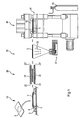
- a loading and unloading zone 10 a heating zone 20, a temperature measuring station 30 and a deformation zone 40 is formed.
- a guided on rails 2 carriage 3 transports a rectangular frame 4 from the loading and unloading zone 10 via the heating zone 20 and the temperature measuring station 30 in the deformation zone 40 and back.
- To drive the carriage 3 is a - not shown - designed for high accelerations and high feed speed stepper motor; For example, the carriage 3 can be adjusted at a speed of 1,400 mm / sec.
- a flat, printed, metallized and / or otherwise coated and to be deformed piece of film 5 is attached by hand or automatically to the frame 4 in a defined arrangement.
- the film piece 5 is supported only with its peripheral portions on the frame 4.
- the heating zone 20 is delimited by an upper heating field 21 and by a lower heating field 22.
- Silk heating panels 21 and 22 are formed coextensive, aligned horizontally and at a distance of about 100 mm from each other and aligned with each other.
- Each heating field 21, 22 has, for example, forty-two infrared surface radiators 23, which each have dimensions of 60 ⁇ 60 mm and can be individually controlled.
- Temperature radiation 32 detected and evaluated.
- the temperature distribution obtained in this way can be displayed on a screen, not shown, with each field of the screen being assigned to each pair of infrared emitter pairs 23 '/ 23 "which can be aligned with each other indicated by a color coding and / or numerically.
- the deformation zone 40 may be equipped with a press 41 with molding tool 42, as in the document DE 41 13 568 C1 described.
- a compressed air tank 43 is connected, is provided from the compressed air.
- the imported from the carriage 3 in the open mold 42 frame 4 is placed within the mold 42 fit.
- the mold 42 is closed by means of the press 41, and held on the frame 4 piece of film 5 is applied directly and directly with heated compressed air under a fluid pressure of, for example, 160 bar and formed isostatically abruptly to the contour of the mold 42.
- a fluid pressure of, for example, 160 bar and formed isostatically abruptly to the contour of the mold 42.
- at least one side of the film section of the film piece 5 held on the frame 4 has the film surface temperature provided according to the invention.
- the mold 42 is opened, and the carriage 3 transports the frame 4 with the deformed piece of film or deep drawn part back into the loading and unloading zone 10. There, the deep-drawn part automatically or by hand from the frame 4 and released from the device. 1 be removed.
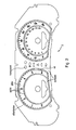
- This in Fig. 2 Deep-drawn part shown has a length of 360 mm and a height of 105 mm.
- the speedometer disc and the tachometer disc each have a diameter of 113 mm.
- the plate of the disc is black, the numerals are white against a gray background, and the marginal strip segment between the numerals "5" and "6" of the tachometer disc is red.
- the pictograms arranged between the two panes are translucent and are each visible upon activation of a respective associated backlight. Noticeable is an initial step-shaped and then conical rise from the plate plane to a silver-colored edge bead, which ends about 12 mm above the plate plane. At this silver-colored edge bead, the white markings on the numbers are limited by very fine black margins.
- the starting material used was a 375 ⁇ m thick, finely matted PC film on a surface (Makrofol® OE from BAYER MATERIALSCIENCE AG), which was applied to the non-matted surface in the multistage screen printing process with the above-mentioned, high-temperature resistant and flexible color prints has been printed.
- the silver-colored ring was applied using an Al-bronze suspension.
- the thus printed flat film pieces were heated in the heating zone to the film surface temperatures given in Table 1 below without prior tempering treatment; the residence time in the heating zone controls the film surface temperature achieved.
- the film surface temperature was measured using the thermal imager on the underside of the film.
- the film tail segments forming the bead were heated to an elevated temperature which exceeded the film surface temperature by about 5 ° C;
- the infrared surface-area radiator pairs associated with these selected foil segments were driven with a higher electrical power consumption.
- the film After reaching the specified film surface temperature, the film was transferred immediately and quickly (within a time less than 1 sec) in the deformation zone and formed there immediately and suddenly.
- the film piece which still had the respective surface temperature of the film, was exposed to about 70 ° C. warm compressed air under a compressed air pressure of 160 bar.
- the high temperature phase from the achievement of the film surface temperature to the completion of the deformation of a given film piece lasted less than 5 seconds.
- tachometer disc has a diameter of 100 mm.
- the plate is black, the lettering including the numbers is white, and the marginal strip segments between the numbers 40 and 60 are red.
- the pictograms grouped around the central opening are translucent and are each visible upon activation of each associated backlight. Striking is the silver-colored, conically rising edge bead, which ends 5 mm above the plane of the plate. At this silver-colored edge bead, the white markings to be shown on the numbers are delimited by very fine black marginal stripes.
- the starting material used was a 250 ⁇ m thick, clear PMMA film (Plexiglas® film "Clear 99524" from Röhm GmbH & Co. KG), which was applied on a surface in several stages with temperature-resistant and flexible colored lacquers according to the graphic design of the tachometer dial Fig. 3 has been printed.
- the silver-colored ring has been applied using an Al-bronze suspension.
- a textured paint layer has been applied to a "matte effect" or the to achieve required feel.
- a hardcoat coating has been applied to this later front, which provided an additional improvement in the scratch resistance of the surface of the deep drawn part.
- Comparative Example 2 210 ° C 197 ° C almost tension-free dial, ie very good flatness after separation; Accurate shaping of all radii and transitions, slight “overblowing” of the edge, slight blistering by outdiffusion of the solvent Structure of the surface is damaged; matt black film content is "greasy" (gloss leveling) Deformation process too hot, film structure becomes plastic, positioning of the symbols changes / does not repeat exactly: color system throws bubbles; Shape OK Appearance Color and texture Nil; * Core temperature has been estimated from various internal observations and experience Deformation of a PMMA film at different temperatures example Surface temperature of the film Core temperature * of the film Verform mit surface finish comment Comparative Example 3 100 ° C 90 ° C negative; Torn / broken film Deformation process too cold, film material too brittle at this temperature; no deformation possible Comparative Example 4 120 ° C 110 ° C Foil not broken; Formation not optimal white break; distinct stresses in the deformation area; Tears within the film material recognizable; Surface not homogen
Landscapes
- Engineering & Computer Science (AREA)
- Mechanical Engineering (AREA)
- Manufacturing & Machinery (AREA)
- Blow-Moulding Or Thermoforming Of Plastics Or The Like (AREA)
- Laminated Bodies (AREA)
- Shaping Of Tube Ends By Bending Or Straightening (AREA)
- Casting Or Compression Moulding Of Plastics Or The Like (AREA)
Claims (15)
- Procédé pour la production d'une pièce en feuille emboutie au moins partiellement imprimée, métallisée et/ou revêtue d'une manière quelconque, présentant au moins les étapes de procédé suivantes :- mise à disposition d'un morceau de feuille, plan, au moins partiellement imprimé, métallisé et/ou revêtu d'une manière quelconque sur une ou les deux faces, en au moins un matériau synthétique thermoplastique, qui comprend au moins une section de feuille qui correspond, en ce qui concerne la taille et l'impression, la métallisation et/ou le revêtement, à la pièce emboutie à produire ;- ce morceau de feuille est agencé dans une disposition définie dans un cadre, où seules les sections de bord du morceau de feuille se placent sur le cadre ;- le morceau de feuille ainsi placé sur le cadre est introduit dans une zone de chauffage et au moins la section de feuille y est chauffée à une température prédéfinie ; et- le morceau de feuille ainsi chauffé est ensuite introduit rapidement dans une zone de déformation et y est soumis immédiatement et directement à un agent sous pression fluide à une pression d'agent sous pression supérieure à 20 bars et déformé de manière isostatique en un laps de temps inférieur à 5 secondes en pièce emboutie souhaitée,
caractérisé en ce qu'on réalise un chauffage tel qu'au moins une face de la section de feuille totale ou de la partie principale de la section de feuille présente une température superficielle de feuille dans la plage de 10 à 65°C au-dessus de la température de ramollissement de Vicat B/50. - Procédé selon la revendication 1, caractérisé en ce qu'il s'agit, pour le matériau synthétique thermoplastique, de polycarbonates ou de copolycarbonates à base de diphénols, de polyacrylates ou de copolyacrylates, de polyméthacrylates ou de copolyméthacrylates, de polymères ou de copolymères avec du styrène, de polyuréthanes thermoplastiques, de polyoléfines, de produits de polycondensation ou de copolycondensation de l'acide téréphtalique ou de mélanges de ceux-ci.
- Procédé selon la revendication 1 ou 2 pour la production d'une pièce en feuille emboutie au moins partiellement imprimée, métallisée et/ou revêtue d'une manière quelconque, présentant au moins les étapes de procédé suivantes :- mise à disposition d'un morceau de feuille, plan, au moins partiellement imprimé, métallisé et/ou revêtu d'une manière quelconque sur une ou les deux faces, en polycarbonate, qui comprend au moins une section de feuille qui correspond, en ce qui concerne la taille et l'impression, la métallisation et/ou le revêtement, à la pièce emboutie à produire ;- ce morceau de feuille est agencé dans une disposition définie dans un cadre, où seules les sections de bord du morceau de feuille se placent sur le cadre ;- le morceau de feuille ainsi placé sur le cadre est introduit dans une zone de chauffage et au moins la section de feuille y est chauffée à une température prédéfinie ; et- le morceau de feuille ainsi chauffé est ensuite introduit rapidement dans une zone de déformation et y est soumis immédiatement et directement à un agent sous pression fluide à une pression d'agent sous pression supérieure à 20 bars et déformé de manière isostatique en un laps de temps inférieur à 5 secondes en pièce emboutie souhaitée,
caractérisé en ce qu'on réalise un chauffage tel qu'au moins une face de la section de feuille totale ou de la partie principale de la section de feuille présente une température superficielle de feuille dans la plage de 180 à 200°C. - Procédé selon la revendication 3, caractérisé- en ce que le morceau de feuille, pour le chauffage dans la zone de chauffage, est maintenu pendant un certain laps de temps, à une certaine distance d'au moins un champ chauffant constitué par un certain nombre d'émetteurs plats d'infrarouges pouvant être commandés individuellement ; et- le morceau de feuille ainsi chauffé passe, sur le trajet de la zone de chauffage à la zone de déformation, dans un poste de mesure de la température, dans lequel, à l'aide d'une chambre d'image thermique, la répartition de la température sur une surface de la feuille est détectée, visualisée et/ou représentée d'une manière quelconque ; et- en ce qu'un chauffage différentiel est réalisé,
où chaque émetteur plat d'infrarouges individuel est contrôlé individuellement de manière à- minimiser les différences de température visibles par la répartition de la température sur la section de feuille, et- chauffer au moins une face de la section principale de la feuille à une température superficielle de la feuille dans la plage de 180°C à 200°C, et- chauffer au choix différents segments choisis du morceau de feuille à une température supérieure, qui dépasse cette température superficielle de feuille d'au moins 3°C et de pas plus de 10°C. - Procédé selon la revendication 3 ou 4, caractérisé en ce qu'au moins une face de la section de feuille totale ou de la partie principale de la section de feuille est chauffée à une température superficielle de feuille dans la plage de 185 à 195°C.
- Procédé selon la revendication 1 ou 2 pour la production d'une pièce en feuille emboutie au moins partiellement imprimée, métallisée et/ou revêtue d'une manière quelconque, présentant au moins les étapes de procédé suivantes :- mise à disposition d'un morceau de feuille, plan, au moins partiellement imprimé, métallisé et/ou revêtu d'une manière quelconque sur une ou les deux faces, en poly(méthacrylate de méthyle) ou en poly(méth)acrylate, qui comprend au moins une section de feuille qui correspond, en ce qui concerne la taille et l'impression, la métallisation et/ou le revêtement, à la pièce emboutie à produire ;- ce morceau de feuille est agencé dans une disposition définie dans un cadre, où seules les sections de bord du morceau de feuille se placent sur le cadre ;- le morceau de feuille ainsi placé sur le cadre est introduit dans une zone de chauffage et au moins la section de feuille y est chauffée à une température prédéfinie ; et- le morceau de feuille ainsi chauffé est ensuite introduit rapidement dans une zone de déformation et y est soumis immédiatement et directement à un agent sous pression fluide à une pression d'agent sous pression supérieure à 20 bars et déformé de manière isostatique en un laps de temps inférieur à 5 secondes en pièce emboutie souhaitée,
caractérisé en ce qu'on réalise un chauffage tel qu'au moins une face de la section de feuille totale ou de la partie principale de la section de feuille présente une température superficielle de feuille dans la plage de 130 à 150°C. - Procédé selon la revendication 6, caractérisé- en ce que le morceau de feuille, pour le chauffage dans la zone de chauffage, est maintenu pendant un certain laps de temps, à une certaine distance d'au moins un champ chauffant constitué par un certain nombre d'émetteurs plats d'infrarouges pouvant être commandés individuellement ; et- le morceau de feuille ainsi chauffé passe, sur le trajet de la zone de chauffage à la zone de déformation, dans un poste de mesure de la température, dans lequel, à l'aide d'une chambre d'image thermique, la répartition de la température sur une surface de la feuille est détectée, visualisée et/ou représentée d'une manière quelconque ; et- en ce qu'un chauffage différentiel est réalisé,
où chaque émetteur plat d'infrarouges individuel est contrôlé individuellement de manière à- minimiser les différences de température visibles par la répartition de la température sur la section de feuille, et- chauffer au moins une face de la section principale de la feuille à une température superficielle de la feuille dans la plage susmentionnée pour chaque matériau de feuille, et- chauffer au choix différents segments choisis du morceau de feuille à une température supérieure, qui dépasse cette température superficielle de feuille d'au moins 3°C et de pas plus de 10°C. - Procédé selon la revendication 4 ou 7, caractérisé en ce qu'on choisit des segments de morceau de feuille dans lesquels une souplesse plus élevée du matériau de feuille doit être atteinte.
- Procédé selon la revendication 8, caractérisé en ce qu'on choisit des segments de morceau de feuille dans lesquels une déformation particulièrement forte de la feuille plane au départ doit être réalisée ou dans lesquels une conformation exacte de contours à arêtes vives, une reproduction précise d'empreintes et/ou de ciselages particulièrement fins, ainsi qu'une correction de déviations de position provoquées par la pression doivent être réalisées.
- Procédé selon l'une quelconque des revendications 4 et 7 à 9, caractérisé- en ce qu'on produit un certain nombre de pièces de feuille embouties de même type ; et- l'étape de procédé de mesure et d'évaluation de la répartition de température sur une surface de la feuille n'est réalisée que lors de la production d'une partie de toutes les pièces en feuille embouties de ce type ; et lors de la production de la partie résiduelle des pièces en feuille embouties de ce type, cette étape de procédé n'est pas réalisée.
- Procédé selon l'une quelconque des revendications 1 à 10, caractérisé en ce que la pièce en feuille se trouvant sur le cadre est introduite dans une zone de chauffage qui présente deux champs chauffants de même superficie, orientés horizontalement, disposés parallèlement à une certaine distance l'un de l'autre et alignés l'un sur l'autre ; et le morceau de feuille est disposé environ au centre entre ces deux champs chauffants et y est maintenu pendant un certain laps de temps pour le chauffage à la température superficielle à chaque fois prévue de la feuille.
- Procédé selon l'une quelconque des revendications 1 à 11, caractérisé en ce que le morceau de feuille, après le chauffage à la température superficielle à chaque fois prévue de la feuille, est transféré en un laps de temps de moins de 5 sec, de préférence de moins de 2 sec, dans la zone de déformation.
- Procédé selon l'une quelconque des revendications 1 à 12, caractérisé en ce qu'on transforme des morceaux de feuille transparents, qui ont été imprimés, métallisés et/ou revêtus d'une manière quelconque selon un modèle prédéfini.
- Procédé selon l'une quelconque des revendications 1 à 13, caractérisé en ce qu'on transforme des morceaux de feuille à une couche, qui ont été imprimés, métallisés et/ou revêtus d'une manière quelconque selon un modèle prédéfini.
- Procédé selon l'une quelconque des revendications 1 à 14, caractérisé en ce qu'il s'agit, pour les morceaux de feuille à déformer, d'une feuille coextrudée à plusieurs couches ou d'une feuille laminée constituée par au moins deux matériaux synthétiques thermoplastiques différents.
Applications Claiming Priority (2)
| Application Number | Priority Date | Filing Date | Title |
|---|---|---|---|
| DE102007046472A DE102007046472B4 (de) | 2007-09-28 | 2007-09-28 | Verfahren zur Herstellung eines tiefgezogenen Folienteils aus Polycarbonat oder aus Polymethylmethacrylat |
| PCT/EP2008/008182 WO2009043539A2 (fr) | 2007-09-28 | 2008-09-26 | Procédé de réalisation d'une pièce mince emboutie en matière thermoplastique |
Publications (3)
| Publication Number | Publication Date |
|---|---|
| EP2197656A2 EP2197656A2 (fr) | 2010-06-23 |
| EP2197656B1 true EP2197656B1 (fr) | 2011-08-24 |
| EP2197656B2 EP2197656B2 (fr) | 2018-11-28 |
Family
ID=40417619
Family Applications (1)
| Application Number | Title | Priority Date | Filing Date |
|---|---|---|---|
| EP08802639.8A Active EP2197656B2 (fr) | 2007-09-28 | 2008-09-26 | Procédé de réalisation d'une pièce mince emboutie en matière thermoplastique |
Country Status (13)
| Country | Link |
|---|---|
| US (1) | US8168110B2 (fr) |
| EP (1) | EP2197656B2 (fr) |
| JP (1) | JP5523322B2 (fr) |
| KR (1) | KR101497174B1 (fr) |
| CN (1) | CN101808803B (fr) |
| AT (1) | ATE521469T1 (fr) |
| BR (1) | BRPI0817642B1 (fr) |
| DE (1) | DE102007046472B4 (fr) |
| ES (1) | ES2369729T5 (fr) |
| MX (1) | MX2010002744A (fr) |
| MY (1) | MY152776A (fr) |
| RU (2) | RU2491166C9 (fr) |
| WO (1) | WO2009043539A2 (fr) |
Cited By (3)
| Publication number | Priority date | Publication date | Assignee | Title |
|---|---|---|---|---|
| DE102016004047A1 (de) | 2016-04-04 | 2017-10-05 | Niebling Gmbh | Verfahren und Formwerkzeug zur Warmumformung eines ebenen thermoplastischen Schichtstoffes |
| WO2018073111A1 (fr) | 2016-10-18 | 2018-04-26 | Covestro Deutschland Ag | Procédé pour la fabrication d'un corps en matière synthétique qui convient comme élément décoratif |
| WO2023174782A1 (fr) | 2022-03-16 | 2023-09-21 | Covestro Deutschland Ag | Corps multicouche translucide à couche décorative sensible à la chaleur ou à la pression |
Families Citing this family (34)
| Publication number | Priority date | Publication date | Assignee | Title |
|---|---|---|---|---|
| DE102008061724B4 (de) * | 2008-01-31 | 2012-04-19 | Johnson Controls Automotive Electronics Gmbh | Anzeigevorrichtung, Folie und Verfahren zu deren Herstellung |
| DE102008050564B4 (de) | 2008-09-22 | 2011-01-20 | Curt Niebling | Formwerkzeug und Verfahren zur Hochdruckumformung eines einlagigen oder mehrlagigen Schichtstoffes |
| DE102009048284B4 (de) * | 2009-10-05 | 2023-06-01 | Bayerische Motoren Werke Aktiengesellschaft | Verfahren zur Herstellung eines Ziffernblattes eines Kraftfahrzeuges sowie Ziffernblatt eines Kraftfahrzeuges |
| DE102009048334A1 (de) | 2009-10-06 | 2011-04-21 | Curt Niebling | 3D-Folienteil und Verfahren zu seiner Herstellung |
| EP2335905A1 (fr) | 2009-12-17 | 2011-06-22 | Bayer MaterialScience AG | Procédé de fabrication d'une partie de feuille emboutie en matière synthétique thermoplastique |
| EP2338664A1 (fr) | 2009-12-23 | 2011-06-29 | Bayer MaterialScience AG | Procédé de fabrication d'une partie de feuille déformée en matière synthétique thermoplastique |
| WO2011114484A1 (fr) * | 2010-03-18 | 2011-09-22 | トヨタ自動車株式会社 | Procédé d'application d'un film de résine et dispositif d'application associé |
| DE102010021892B4 (de) | 2010-05-28 | 2014-03-20 | Curt Niebling jun. | Verfahren und Vorrichtung zur Kaschierung eines 3D-Trägerteils mit einem Schichtstoff |
| US9457510B2 (en) * | 2010-06-01 | 2016-10-04 | William C. Shanley, Iv | Apparatus and methods for selective thermoforming |
| EP2395572A1 (fr) | 2010-06-10 | 2011-12-14 | Bayer MaterialScience AG | Montage en couche comprenant des composants électrotechniques |
| EP2429264A1 (fr) | 2010-09-13 | 2012-03-14 | Bayer MaterialScience AG | Montage en couche comprenant un commutateur éclairé par un agencement ACPEL |
| DE102010061963A1 (de) | 2010-11-25 | 2012-05-31 | Bayer Materialscience Aktiengesellschaft | EL-Elemente enthaltend eine Pigmentschicht mit vernetzenden Systemen mit blockierten Isocyanat-Gruppen |
| EP2489492A1 (fr) | 2011-02-17 | 2012-08-22 | Bayer MaterialScience AG | Procédé d'équilibrage d'oscillations partiel dans des pièces de formage en matière synthétique |
| EP2497637A1 (fr) | 2011-03-10 | 2012-09-12 | Bayer MaterialScience AG | Feuille en plastique transparente galvanisable pour la galvanisation partielle |
| US9610726B1 (en) * | 2012-03-12 | 2017-04-04 | Specialty Manufacturing Inc. | Thermoforming with precision in-lay |
| JP2015521552A (ja) * | 2012-07-04 | 2015-07-30 | エボニック インダストリーズ アクチエンゲゼルシャフトEvonik Industries AG | 熱成形プロセス及び使用 |
| DE102012018447A1 (de) | 2012-09-18 | 2014-03-20 | GM Global Technology Operations, LLC (n.d. Ges. d. Staates Delaware) | Kraftfahrzeugkarosserie |
| AT514454B1 (de) | 2013-07-11 | 2015-03-15 | Engel Austria Gmbh | Heizvorrichtung |
| WO2015025285A2 (fr) | 2013-08-20 | 2015-02-26 | Sabic Innovative Plastics Ip B.V. | Procédé de formation d'articles à partir d'une feuille polymère extrudée |
| DE102015012242B4 (de) * | 2015-09-18 | 2019-06-19 | Leonhard Kurz Stiftung & Co. Kg | Verfahren und Vorrichtung zur Herstellung eines mit einem Schichtstoff kaschierten 3D-Substrates |
| DE102015014219A1 (de) * | 2015-11-04 | 2017-05-04 | Audi Ag | Verfahren zum Herstellen eines Bauelements für ein Kraftfahrzeug |
| DE102016112121A1 (de) * | 2016-07-01 | 2018-01-04 | Brückner Maschinenbau GmbH & Co. KG | Steuerungsvorrichtung zur Herstellung und/oder Behandlung einer Kunststoff-Folie sowie zugehöriges Verfahren |
| WO2018091556A1 (fr) * | 2016-11-17 | 2018-05-24 | Covestro Deutschland Ag | Corps multicouche transparent pour la gestion de la chaleur |
| CN108422607B (zh) * | 2018-02-10 | 2020-05-08 | 诸暨市烈火工业设计工作室 | 一种照明灯罩制作设备 |
| TWI671177B (zh) * | 2018-10-01 | 2019-09-11 | 中原大學 | 射出成型設備 |
| KR102307987B1 (ko) * | 2018-11-20 | 2021-09-30 | (주)엘엑스하우시스 | 데코레이션 필름을 진공 열성형하는 방법 |
| US11014029B2 (en) * | 2019-05-24 | 2021-05-25 | Ultra Small Fibers, LLC | Filter media ribbons with nanofibers formed thereon |
| IT201900019001A1 (it) * | 2019-10-16 | 2021-04-16 | Cms Spa | Metodo di controllo e macchina termoformatrice |
| CN112172347B (zh) * | 2020-09-15 | 2021-05-07 | 温州大学 | 一种用于包装盒的印刷烘干镀膜激光加工工艺 |
| JP7791877B2 (ja) | 2020-09-18 | 2025-12-24 | コベストロ、ドイチュラント、アクチエンゲゼルシャフト | 拡散性透過照光用の多層体 |
| CN114953403A (zh) * | 2021-02-18 | 2022-08-30 | 中兴通讯股份有限公司 | 柔性电路板的热成型装置及方法 |
| US20240399637A1 (en) * | 2021-09-14 | 2024-12-05 | Trinseo Europe Gmbh | Articles of manufacture produced from acrylic/abs laminated sheet |
| WO2023200471A2 (fr) | 2021-09-24 | 2023-10-19 | Carnegie Mellon University | Procédé de stimulation par courant électrique transcrânien focalisé |
| DE202022106307U1 (de) * | 2022-11-10 | 2024-02-14 | Engel Austria Gmbh | Heizanordnung und Anordnung einer Formgebungsmaschine mit einer Heizanordnung |
Family Cites Families (31)
| Publication number | Priority date | Publication date | Assignee | Title |
|---|---|---|---|---|
| US3342915A (en) * | 1965-02-03 | 1967-09-19 | Illinois Tool Works | Undercut molding apparatus and method |
| US3462249A (en) | 1967-03-31 | 1969-08-19 | Exxon Research Engineering Co | Fuel oil compositions containing grafted polymers |
| FR1580834A (fr) | 1968-01-04 | 1969-09-12 | ||
| LU66646A1 (fr) * | 1972-12-13 | 1974-07-10 | ||
| US4034054A (en) * | 1974-09-20 | 1977-07-05 | National Can Corporation | Process for thermoforming hollow articles |
| DE3530309A1 (de) * | 1985-08-24 | 1987-02-26 | Held Kurt | Verfahren und vorrichtung zum kontinuierlichen herstellen thermoplastischer kunststoffbahnen |
| FR2602174B1 (fr) * | 1986-07-31 | 1988-11-18 | Erca Holding | Procede et dispositif de reglage de l'echauffement d'une bande thermoplastique utilisee dans un poste de thermoformage |
| DE3844633A1 (de) | 1988-08-12 | 1990-04-19 | Bayer Ag | Dihydroxydiphenylcycloalkane, ihre herstellung und ihre verwendung zur herstellung von hochmolekularen polycarbonaten |
| US5275866A (en) * | 1988-08-17 | 1994-01-04 | Atochem Puteaux | Thermoformed poly (methyl methacrylate) sheets with protective film and adhesion layer |
| DE58909087D1 (de) * | 1988-12-01 | 1995-04-13 | Bayer Ag | Verfahren zur Herstellung tiefgezogener Kunststoff-Formteile. |
| US5217563A (en) * | 1988-12-01 | 1993-06-08 | Bayer Aktiengesellschaft | Apparatus for producing a deep-drawn formed plastic piece |
| DE4113568C1 (fr) | 1991-04-25 | 1992-05-21 | Curt 8122 Penzberg De Niebling | |
| RU2173471C2 (ru) * | 1996-04-30 | 2001-09-10 | Миннесота Майнинг Энд Мэнюфекчуринг Компани | Формованный сверхгибкий композитный световозвращающий листовой материал с кубическими уголковыми элементами, имеющий заданные оптические характеристики, и способ его изготовления |
| US5763335A (en) * | 1996-05-21 | 1998-06-09 | H.H. Brown Shoe Technologies, Inc. | Composite material for absorbing and dissipating body fluids and moisture |
| US6257866B1 (en) * | 1996-06-18 | 2001-07-10 | Hy-Tech Forming Systems, Inc. | Apparatus for accurately forming plastic sheet |
| US6132669A (en) | 1997-08-14 | 2000-10-17 | The Elizabeth And Sandor Valyi Foundation, Inc. | Process for preparing a molded article |
| DE19832570C2 (de) | 1998-07-20 | 2002-03-28 | Mcgavigan John Ltd | Hochtemperaturbeständige flexible Druckfarbe und deren Verwendung |
| DE69930193T2 (de) * | 1998-12-14 | 2006-07-27 | Toray Industries, Inc. | Verfahren und Vorrichtung zur Herstellung von Kunststofffolien |
| US6506334B1 (en) | 2000-09-22 | 2003-01-14 | The University Of Massachusetts | Process and apparatus for preparing a molded article |
| JP3514726B2 (ja) * | 2000-12-26 | 2004-03-31 | 日本写真印刷株式会社 | 光輝性加飾シートおよび該シートを用いた光輝性加飾品の製造方法 |
| JP2003245939A (ja) * | 2002-02-25 | 2003-09-02 | Nissha Printing Co Ltd | キーシート部材の製造方法 |
| US6749794B2 (en) * | 2001-08-13 | 2004-06-15 | R + S Technik Gmbh | Method and apparatus for molding components with molded-in surface texture |
| WO2003018697A1 (fr) * | 2001-08-27 | 2003-03-06 | Röhm GmbH & Co. KG | Laque coloree pour serigraphier la face interieure de pieces de moulage d'inserts |
| DE10151281A1 (de) | 2001-08-27 | 2003-03-20 | Roehm Gmbh | Farblack für die Siebbedruckung der Innenseite von Insert-Moulding-Teilen |
| JP2003200486A (ja) * | 2001-12-28 | 2003-07-15 | Nissha Printing Co Ltd | 深絞り形状加飾シートの製造方法 |
| DE10312610A1 (de) * | 2003-03-21 | 2004-09-30 | Bayer Ag | Verfahren zum Hinterspritzen von dekorierten Folien |
| CN2635343Y (zh) * | 2003-08-04 | 2004-08-25 | 潍坊中云机器有限公司 | 塑料波纹管成型机风冷装置 |
| DE102004049592A1 (de) | 2004-10-12 | 2006-05-04 | Bayer Materialscience Ag | Mit Soft-Touch-Lack beschichtete, verformbare Kunststoffverbundfolien und Kunststoffverbundelemente sowie deren Herstellung |
| JP2006130774A (ja) * | 2004-11-05 | 2006-05-25 | Shin Etsu Polymer Co Ltd | 成形用加飾シートおよび加飾付き成形体 |
| DE102005050072A1 (de) | 2005-10-19 | 2007-04-26 | Bayer Materialscience Ag | Lichtstreuende Folien sowie deren Verwendung in Flachbildschirmen |
| US20080020210A1 (en) * | 2006-07-19 | 2008-01-24 | Griffin Patrick J | Metallized multilayered composite |
-
2007
- 2007-09-28 DE DE102007046472A patent/DE102007046472B4/de active Active
-
2008
- 2008-09-26 KR KR1020107006605A patent/KR101497174B1/ko active Active
- 2008-09-26 BR BRPI0817642A patent/BRPI0817642B1/pt not_active IP Right Cessation
- 2008-09-26 WO PCT/EP2008/008182 patent/WO2009043539A2/fr not_active Ceased
- 2008-09-26 RU RU2010116549/05A patent/RU2491166C9/ru active
- 2008-09-26 MX MX2010002744A patent/MX2010002744A/es active IP Right Grant
- 2008-09-26 JP JP2010526210A patent/JP5523322B2/ja active Active
- 2008-09-26 RU RU2013120106A patent/RU2641934C2/ru active
- 2008-09-26 EP EP08802639.8A patent/EP2197656B2/fr active Active
- 2008-09-26 CN CN200880109381XA patent/CN101808803B/zh active Active
- 2008-09-26 US US12/680,360 patent/US8168110B2/en active Active
- 2008-09-26 AT AT08802639T patent/ATE521469T1/de active
- 2008-09-26 MY MYPI20101307 patent/MY152776A/en unknown
- 2008-09-26 ES ES08802639T patent/ES2369729T5/es active Active
Cited By (5)
| Publication number | Priority date | Publication date | Assignee | Title |
|---|---|---|---|---|
| DE102016004047A1 (de) | 2016-04-04 | 2017-10-05 | Niebling Gmbh | Verfahren und Formwerkzeug zur Warmumformung eines ebenen thermoplastischen Schichtstoffes |
| WO2017174176A1 (fr) | 2016-04-04 | 2017-10-12 | Niebling Gmbh | Procédé et outil de formage pour former à chaud un matériau stratifié thermoplastique plan |
| DE102016004047B4 (de) * | 2016-04-04 | 2017-10-19 | Niebling Gmbh | Verfahren und Formwerkzeug zur Warmumformung eines ebenen thermoplastischen Schichtstoffes |
| WO2018073111A1 (fr) | 2016-10-18 | 2018-04-26 | Covestro Deutschland Ag | Procédé pour la fabrication d'un corps en matière synthétique qui convient comme élément décoratif |
| WO2023174782A1 (fr) | 2022-03-16 | 2023-09-21 | Covestro Deutschland Ag | Corps multicouche translucide à couche décorative sensible à la chaleur ou à la pression |
Also Published As
| Publication number | Publication date |
|---|---|
| MX2010002744A (es) | 2010-04-01 |
| CN101808803B (zh) | 2013-03-27 |
| WO2009043539A3 (fr) | 2009-11-12 |
| DE102007046472A1 (de) | 2009-04-09 |
| JP5523322B2 (ja) | 2014-06-18 |
| RU2491166C2 (ru) | 2013-08-27 |
| MY152776A (en) | 2014-11-28 |
| ES2369729T5 (es) | 2019-05-23 |
| BRPI0817642A2 (pt) | 2017-05-16 |
| KR101497174B1 (ko) | 2015-02-27 |
| DE102007046472B4 (de) | 2013-12-24 |
| JP2010540272A (ja) | 2010-12-24 |
| EP2197656B2 (fr) | 2018-11-28 |
| RU2010116549A (ru) | 2011-11-10 |
| WO2009043539A2 (fr) | 2009-04-09 |
| CN101808803A (zh) | 2010-08-18 |
| BRPI0817642B1 (pt) | 2018-09-18 |
| KR20100058602A (ko) | 2010-06-03 |
| US20100237544A1 (en) | 2010-09-23 |
| RU2491166C9 (ru) | 2014-01-27 |
| EP2197656A2 (fr) | 2010-06-23 |
| RU2641934C2 (ru) | 2018-01-23 |
| ATE521469T1 (de) | 2011-09-15 |
| RU2013120106A (ru) | 2014-11-10 |
| ES2369729T3 (es) | 2011-12-05 |
| US8168110B2 (en) | 2012-05-01 |
Similar Documents
| Publication | Publication Date | Title |
|---|---|---|
| EP2197656A2 (fr) | Procédé de réalisation d'une pièce mince emboutie en matière thermoplastique | |
| EP3439850B1 (fr) | Procédé et outil de formage pour former à chaud un matériau stratifié thermoplastique plan | |
| EP2602108A1 (fr) | Film multicouche, film de moulage décoratif et corps moulé | |
| WO2014044694A1 (fr) | Procédé de fabrication d'une pièce moulée en plastique pourvue d'une peinture durcie par uv ainsi que pièce moulée | |
| EP2683551B1 (fr) | Feuille transparente en matière plastique pouvant être traitée par électrodéposition, destinée à être partiellement traitée par électrodéposition | |
| JP6903569B2 (ja) | 合わせガラス用中間膜、合わせガラス及び合わせガラスの製造方法 | |
| EP2172336A1 (fr) | Caractéristiques de sécurité protégées contre la falsification dans des documents de sécurité ou de valeur | |
| KR20140036263A (ko) | 카드용 시트 | |
| EP3890971B1 (fr) | Feuilles en matière plastique à température de ramollissement vicat plus élevée dans les structures stratifiées | |
| EP3727851B1 (fr) | Feuilles en matière plastique pour document d'id à luminosité des hologrammes estampés améliorée | |
| WO2013107777A1 (fr) | Feuille plastique pour impression par transfert thermique par diffusion de colorants | |
| EP2335905A1 (fr) | Procédé de fabrication d'une partie de feuille emboutie en matière synthétique thermoplastique | |
| KR101786149B1 (ko) | 성형성이 우수한 고광택 인테리어용 장식필름 | |
| EP2489493A2 (fr) | Procédé d'équilibrage d'oscillations partiel pour des pièces de formage en matière synthétique | |
| WO2011076717A1 (fr) | Procédé pour fabriquer un ensemble de feuilles déformé à base de plastique thermoplastique | |
| WO2020099344A1 (fr) | Films plastiques présentant une opacité élevée et une faible transparence pour des documents d'identité pourvus d'une fenêtre transparente | |
| DE102022105839A1 (de) | Verfahren zum Herstellen eines Kunststoff-Formteils | |
| WO2023110961A1 (fr) | Structure stratifiée au moins partiellement d'origine biologique présentant de bonnes propriétés favorables | |
| DE102015006395B4 (de) | Verfahren zum Herstellen eines Bauteils für ein Kraftfahrzeug, Bauteil und Kraftfahrzeug |
Legal Events
| Date | Code | Title | Description |
|---|---|---|---|
| PUAI | Public reference made under article 153(3) epc to a published international application that has entered the european phase |
Free format text: ORIGINAL CODE: 0009012 |
|
| 17P | Request for examination filed |
Effective date: 20100512 |
|
| AK | Designated contracting states |
Kind code of ref document: A2 Designated state(s): AT BE BG CH CY CZ DE DK EE ES FI FR GB GR HR HU IE IS IT LI LT LU LV MC MT NL NO PL PT RO SE SI SK TR |
|
| AX | Request for extension of the european patent |
Extension state: AL BA MK RS |
|
| DAX | Request for extension of the european patent (deleted) | ||
| GRAP | Despatch of communication of intention to grant a patent |
Free format text: ORIGINAL CODE: EPIDOSNIGR1 |
|
| GRAS | Grant fee paid |
Free format text: ORIGINAL CODE: EPIDOSNIGR3 |
|
| GRAA | (expected) grant |
Free format text: ORIGINAL CODE: 0009210 |
|
| AK | Designated contracting states |
Kind code of ref document: B1 Designated state(s): AT BE BG CH CY CZ DE DK EE ES FI FR GB GR HR HU IE IS IT LI LT LU LV MC MT NL NO PL PT RO SE SI SK TR |
|
| REG | Reference to a national code |
Ref country code: GB Ref legal event code: FG4D Free format text: NOT ENGLISH |
|
| REG | Reference to a national code |
Ref country code: CH Ref legal event code: EP |
|
| REG | Reference to a national code |
Ref country code: IE Ref legal event code: FG4D Free format text: LANGUAGE OF EP DOCUMENT: GERMAN |
|
| REG | Reference to a national code |
Ref country code: DE Ref legal event code: R096 Ref document number: 502008004611 Country of ref document: DE Effective date: 20111027 |
|
| REG | Reference to a national code |
Ref country code: ES Ref legal event code: FG2A Ref document number: 2369729 Country of ref document: ES Kind code of ref document: T3 Effective date: 20111205 |
|
| REG | Reference to a national code |
Ref country code: NL Ref legal event code: T3 |
|
| LTIE | Lt: invalidation of european patent or patent extension |
Effective date: 20110824 |
|
| PG25 | Lapsed in a contracting state [announced via postgrant information from national office to epo] |
Ref country code: SE Free format text: LAPSE BECAUSE OF FAILURE TO SUBMIT A TRANSLATION OF THE DESCRIPTION OR TO PAY THE FEE WITHIN THE PRESCRIBED TIME-LIMIT Effective date: 20110824 Ref country code: PT Free format text: LAPSE BECAUSE OF FAILURE TO SUBMIT A TRANSLATION OF THE DESCRIPTION OR TO PAY THE FEE WITHIN THE PRESCRIBED TIME-LIMIT Effective date: 20111226 Ref country code: LT Free format text: LAPSE BECAUSE OF FAILURE TO SUBMIT A TRANSLATION OF THE DESCRIPTION OR TO PAY THE FEE WITHIN THE PRESCRIBED TIME-LIMIT Effective date: 20110824 Ref country code: NO Free format text: LAPSE BECAUSE OF FAILURE TO SUBMIT A TRANSLATION OF THE DESCRIPTION OR TO PAY THE FEE WITHIN THE PRESCRIBED TIME-LIMIT Effective date: 20111124 Ref country code: IS Free format text: LAPSE BECAUSE OF FAILURE TO SUBMIT A TRANSLATION OF THE DESCRIPTION OR TO PAY THE FEE WITHIN THE PRESCRIBED TIME-LIMIT Effective date: 20111224 Ref country code: HR Free format text: LAPSE BECAUSE OF FAILURE TO SUBMIT A TRANSLATION OF THE DESCRIPTION OR TO PAY THE FEE WITHIN THE PRESCRIBED TIME-LIMIT Effective date: 20110824 |
|
| PG25 | Lapsed in a contracting state [announced via postgrant information from national office to epo] |
Ref country code: LV Free format text: LAPSE BECAUSE OF FAILURE TO SUBMIT A TRANSLATION OF THE DESCRIPTION OR TO PAY THE FEE WITHIN THE PRESCRIBED TIME-LIMIT Effective date: 20110824 Ref country code: PL Free format text: LAPSE BECAUSE OF FAILURE TO SUBMIT A TRANSLATION OF THE DESCRIPTION OR TO PAY THE FEE WITHIN THE PRESCRIBED TIME-LIMIT Effective date: 20110824 Ref country code: GR Free format text: LAPSE BECAUSE OF FAILURE TO SUBMIT A TRANSLATION OF THE DESCRIPTION OR TO PAY THE FEE WITHIN THE PRESCRIBED TIME-LIMIT Effective date: 20111125 Ref country code: CY Free format text: LAPSE BECAUSE OF FAILURE TO SUBMIT A TRANSLATION OF THE DESCRIPTION OR TO PAY THE FEE WITHIN THE PRESCRIBED TIME-LIMIT Effective date: 20110824 Ref country code: SI Free format text: LAPSE BECAUSE OF FAILURE TO SUBMIT A TRANSLATION OF THE DESCRIPTION OR TO PAY THE FEE WITHIN THE PRESCRIBED TIME-LIMIT Effective date: 20110824 |
|
| BERE | Be: lapsed |
Owner name: BAYER MATERIALSCIENCE A.G. Effective date: 20110930 |
|
| PG25 | Lapsed in a contracting state [announced via postgrant information from national office to epo] |
Ref country code: MC Free format text: LAPSE BECAUSE OF NON-PAYMENT OF DUE FEES Effective date: 20110930 Ref country code: SK Free format text: LAPSE BECAUSE OF FAILURE TO SUBMIT A TRANSLATION OF THE DESCRIPTION OR TO PAY THE FEE WITHIN THE PRESCRIBED TIME-LIMIT Effective date: 20110824 |
|
| PLBI | Opposition filed |
Free format text: ORIGINAL CODE: 0009260 |
|
| PG25 | Lapsed in a contracting state [announced via postgrant information from national office to epo] |
Ref country code: EE Free format text: LAPSE BECAUSE OF FAILURE TO SUBMIT A TRANSLATION OF THE DESCRIPTION OR TO PAY THE FEE WITHIN THE PRESCRIBED TIME-LIMIT Effective date: 20110824 Ref country code: RO Free format text: LAPSE BECAUSE OF FAILURE TO SUBMIT A TRANSLATION OF THE DESCRIPTION OR TO PAY THE FEE WITHIN THE PRESCRIBED TIME-LIMIT Effective date: 20110824 |
|
| 26 | Opposition filed |
Opponent name: SABIC INNOVATIVE PLASTICS IP B.V. Effective date: 20120507 |
|
| PLAX | Notice of opposition and request to file observation + time limit sent |
Free format text: ORIGINAL CODE: EPIDOSNOBS2 |
|
| PG25 | Lapsed in a contracting state [announced via postgrant information from national office to epo] |
Ref country code: BE Free format text: LAPSE BECAUSE OF NON-PAYMENT OF DUE FEES Effective date: 20110930 Ref country code: DK Free format text: LAPSE BECAUSE OF FAILURE TO SUBMIT A TRANSLATION OF THE DESCRIPTION OR TO PAY THE FEE WITHIN THE PRESCRIBED TIME-LIMIT Effective date: 20110824 |
|
| REG | Reference to a national code |
Ref country code: DE Ref legal event code: R026 Ref document number: 502008004611 Country of ref document: DE Effective date: 20120507 |
|
| PLBB | Reply of patent proprietor to notice(s) of opposition received |
Free format text: ORIGINAL CODE: EPIDOSNOBS3 |
|
| PG25 | Lapsed in a contracting state [announced via postgrant information from national office to epo] |
Ref country code: MT Free format text: LAPSE BECAUSE OF FAILURE TO SUBMIT A TRANSLATION OF THE DESCRIPTION OR TO PAY THE FEE WITHIN THE PRESCRIBED TIME-LIMIT Effective date: 20110824 |
|
| PG25 | Lapsed in a contracting state [announced via postgrant information from national office to epo] |
Ref country code: LU Free format text: LAPSE BECAUSE OF NON-PAYMENT OF DUE FEES Effective date: 20110926 |
|
| PG25 | Lapsed in a contracting state [announced via postgrant information from national office to epo] |
Ref country code: BG Free format text: LAPSE BECAUSE OF FAILURE TO SUBMIT A TRANSLATION OF THE DESCRIPTION OR TO PAY THE FEE WITHIN THE PRESCRIBED TIME-LIMIT Effective date: 20111124 |
|
| PLAB | Opposition data, opponent's data or that of the opponent's representative modified |
Free format text: ORIGINAL CODE: 0009299OPPO |
|
| PG25 | Lapsed in a contracting state [announced via postgrant information from national office to epo] |
Ref country code: TR Free format text: LAPSE BECAUSE OF FAILURE TO SUBMIT A TRANSLATION OF THE DESCRIPTION OR TO PAY THE FEE WITHIN THE PRESCRIBED TIME-LIMIT Effective date: 20110824 |
|
| R26 | Opposition filed (corrected) |
Opponent name: SABIC INNOVATIVE PLASTICS IP B.V. Effective date: 20120507 |
|
| PG25 | Lapsed in a contracting state [announced via postgrant information from national office to epo] |
Ref country code: HU Free format text: LAPSE BECAUSE OF FAILURE TO SUBMIT A TRANSLATION OF THE DESCRIPTION OR TO PAY THE FEE WITHIN THE PRESCRIBED TIME-LIMIT Effective date: 20110824 |
|
| PLAB | Opposition data, opponent's data or that of the opponent's representative modified |
Free format text: ORIGINAL CODE: 0009299OPPO |
|
| APBM | Appeal reference recorded |
Free format text: ORIGINAL CODE: EPIDOSNREFNO |
|
| APBP | Date of receipt of notice of appeal recorded |
Free format text: ORIGINAL CODE: EPIDOSNNOA2O |
|
| APAH | Appeal reference modified |
Free format text: ORIGINAL CODE: EPIDOSCREFNO |
|
| APBM | Appeal reference recorded |
Free format text: ORIGINAL CODE: EPIDOSNREFNO |
|
| APBP | Date of receipt of notice of appeal recorded |
Free format text: ORIGINAL CODE: EPIDOSNNOA2O |
|
| R26 | Opposition filed (corrected) |
Opponent name: SABIC GLOBAL TECHNOLOGIES B.V. Effective date: 20120507 |
|
| REG | Reference to a national code |
Ref country code: DE Ref legal event code: R081 Ref document number: 502008004611 Country of ref document: DE Owner name: COVESTRO DEUTSCHLAND AG, DE Free format text: FORMER OWNER: BAYER MATERIALSCIENCE AKTIENGESELLSCHAFT, 51373 LEVERKUSEN, DE Effective date: 20140526 Ref country code: DE Ref legal event code: R081 Ref document number: 502008004611 Country of ref document: DE Owner name: BAYER INTELLECTUAL PROPERTY GMBH, DE Free format text: FORMER OWNER: BAYER MATERIALSCIENCE AKTIENGESELLSCHAFT, 51373 LEVERKUSEN, DE Effective date: 20140526 |
|
| APBQ | Date of receipt of statement of grounds of appeal recorded |
Free format text: ORIGINAL CODE: EPIDOSNNOA3O |
|
| REG | Reference to a national code |
Ref country code: FR Ref legal event code: PLFP Year of fee payment: 8 |
|
| RAP2 | Party data changed (patent owner data changed or rights of a patent transferred) |
Owner name: COVESTRO DEUTSCHLAND AG |
|
| REG | Reference to a national code |
Ref country code: DE Ref legal event code: R081 Ref document number: 502008004611 Country of ref document: DE Owner name: COVESTRO DEUTSCHLAND AG, DE Free format text: FORMER OWNER: BAYER INTELLECTUAL PROPERTY GMBH, 40789 MONHEIM, DE |
|
| REG | Reference to a national code |
Ref country code: FR Ref legal event code: PLFP Year of fee payment: 9 |
|
| REG | Reference to a national code |
Ref country code: NL Ref legal event code: HC Owner name: COVESTRO DEUTSCHLAND AG; DE Free format text: DETAILS ASSIGNMENT: VERANDERING VAN EIGENAAR(S), VERANDERING VAN NAAM VAN DE EIGENAAR(S); FORMER OWNER NAME: BAYER MATERIALSCIENCE AG Effective date: 20160810 |
|
| REG | Reference to a national code |
Ref country code: FR Ref legal event code: PLFP Year of fee payment: 10 |
|
| APBU | Appeal procedure closed |
Free format text: ORIGINAL CODE: EPIDOSNNOA9O |
|
| PLAB | Opposition data, opponent's data or that of the opponent's representative modified |
Free format text: ORIGINAL CODE: 0009299OPPO |
|
| R26 | Opposition filed (corrected) |
Opponent name: SABIC GLOBAL TECHNOLOGIES B.V. Effective date: 20120507 |
|
| REG | Reference to a national code |
Ref country code: FR Ref legal event code: PLFP Year of fee payment: 11 |
|
| PUAH | Patent maintained in amended form |
Free format text: ORIGINAL CODE: 0009272 |
|
| STAA | Information on the status of an ep patent application or granted ep patent |
Free format text: STATUS: PATENT MAINTAINED AS AMENDED |
|
| REG | Reference to a national code |
Ref country code: CH Ref legal event code: AELC |
|
| 27A | Patent maintained in amended form |
Effective date: 20181128 |
|
| AK | Designated contracting states |
Kind code of ref document: B2 Designated state(s): AT BE BG CH CY CZ DE DK EE ES FI FR GB GR HR HU IE IS IT LI LT LU LV MC MT NL NO PL PT RO SE SI SK TR |
|
| REG | Reference to a national code |
Ref country code: DE Ref legal event code: R102 Ref document number: 502008004611 Country of ref document: DE |
|
| REG | Reference to a national code |
Ref country code: NL Ref legal event code: FP |
|
| REG | Reference to a national code |
Ref country code: ES Ref legal event code: DC2A Ref document number: 2369729 Country of ref document: ES Kind code of ref document: T5 Effective date: 20190523 |
|
| REG | Reference to a national code |
Ref country code: DE Ref legal event code: R082 Ref document number: 502008004611 Country of ref document: DE |
|
| PGFP | Annual fee paid to national office [announced via postgrant information from national office to epo] |
Ref country code: NL Payment date: 20220826 Year of fee payment: 15 |
|
| PGFP | Annual fee paid to national office [announced via postgrant information from national office to epo] |
Ref country code: IT Payment date: 20220829 Year of fee payment: 15 Ref country code: IE Payment date: 20220824 Year of fee payment: 15 Ref country code: GB Payment date: 20220818 Year of fee payment: 15 Ref country code: FI Payment date: 20220909 Year of fee payment: 15 Ref country code: DE Payment date: 20220609 Year of fee payment: 15 Ref country code: CZ Payment date: 20220915 Year of fee payment: 15 Ref country code: AT Payment date: 20220825 Year of fee payment: 15 |
|
| PGFP | Annual fee paid to national office [announced via postgrant information from national office to epo] |
Ref country code: CH Payment date: 20220901 Year of fee payment: 15 |
|
| REG | Reference to a national code |
Ref country code: DE Ref legal event code: R119 Ref document number: 502008004611 Country of ref document: DE |
|
| PG25 | Lapsed in a contracting state [announced via postgrant information from national office to epo] |
Ref country code: FI Free format text: LAPSE BECAUSE OF NON-PAYMENT OF DUE FEES Effective date: 20230926 Ref country code: CZ Free format text: LAPSE BECAUSE OF NON-PAYMENT OF DUE FEES Effective date: 20230926 |
|
| REG | Reference to a national code |
Ref country code: CH Ref legal event code: PL |
|
| REG | Reference to a national code |
Ref country code: NL Ref legal event code: MM Effective date: 20231001 |
|
| REG | Reference to a national code |
Ref country code: AT Ref legal event code: MM01 Ref document number: 521469 Country of ref document: AT Kind code of ref document: T Effective date: 20230926 |
|
| GBPC | Gb: european patent ceased through non-payment of renewal fee |
Effective date: 20230926 |
|
| PG25 | Lapsed in a contracting state [announced via postgrant information from national office to epo] |
Ref country code: NL Free format text: LAPSE BECAUSE OF NON-PAYMENT OF DUE FEES Effective date: 20231001 |
|
| PG25 | Lapsed in a contracting state [announced via postgrant information from national office to epo] |
Ref country code: NL Free format text: LAPSE BECAUSE OF NON-PAYMENT OF DUE FEES Effective date: 20231001 |
|
| REG | Reference to a national code |
Ref country code: IE Ref legal event code: MM4A |
|
| PG25 | Lapsed in a contracting state [announced via postgrant information from national office to epo] |
Ref country code: IE Free format text: LAPSE BECAUSE OF NON-PAYMENT OF DUE FEES Effective date: 20230926 |
|
| PG25 | Lapsed in a contracting state [announced via postgrant information from national office to epo] |
Ref country code: GB Free format text: LAPSE BECAUSE OF NON-PAYMENT OF DUE FEES Effective date: 20230926 |
|
| PG25 | Lapsed in a contracting state [announced via postgrant information from national office to epo] |
Ref country code: CH Free format text: LAPSE BECAUSE OF NON-PAYMENT OF DUE FEES Effective date: 20230930 |
|
| PG25 | Lapsed in a contracting state [announced via postgrant information from national office to epo] |
Ref country code: AT Free format text: LAPSE BECAUSE OF NON-PAYMENT OF DUE FEES Effective date: 20230926 |
|
| PG25 | Lapsed in a contracting state [announced via postgrant information from national office to epo] |
Ref country code: IE Free format text: LAPSE BECAUSE OF NON-PAYMENT OF DUE FEES Effective date: 20230926 Ref country code: GB Free format text: LAPSE BECAUSE OF NON-PAYMENT OF DUE FEES Effective date: 20230926 Ref country code: DE Free format text: LAPSE BECAUSE OF NON-PAYMENT OF DUE FEES Effective date: 20240403 Ref country code: CH Free format text: LAPSE BECAUSE OF NON-PAYMENT OF DUE FEES Effective date: 20230930 Ref country code: AT Free format text: LAPSE BECAUSE OF NON-PAYMENT OF DUE FEES Effective date: 20230926 |
|
| PG25 | Lapsed in a contracting state [announced via postgrant information from national office to epo] |
Ref country code: IT Free format text: LAPSE BECAUSE OF NON-PAYMENT OF DUE FEES Effective date: 20230926 |
|
| PG25 | Lapsed in a contracting state [announced via postgrant information from national office to epo] |
Ref country code: IT Free format text: LAPSE BECAUSE OF NON-PAYMENT OF DUE FEES Effective date: 20230926 |
|
| PGFP | Annual fee paid to national office [announced via postgrant information from national office to epo] |
Ref country code: FR Payment date: 20250821 Year of fee payment: 18 |
|
| PGFP | Annual fee paid to national office [announced via postgrant information from national office to epo] |
Ref country code: ES Payment date: 20251015 Year of fee payment: 18 |