EP2489493A2 - Procédé d'équilibrage d'oscillations partiel pour des pièces de formage en matière synthétique - Google Patents
Procédé d'équilibrage d'oscillations partiel pour des pièces de formage en matière synthétique Download PDFInfo
- Publication number
- EP2489493A2 EP2489493A2 EP12155209A EP12155209A EP2489493A2 EP 2489493 A2 EP2489493 A2 EP 2489493A2 EP 12155209 A EP12155209 A EP 12155209A EP 12155209 A EP12155209 A EP 12155209A EP 2489493 A2 EP2489493 A2 EP 2489493A2
- Authority
- EP
- European Patent Office
- Prior art keywords
- plastic film
- injected
- plastic
- temperature
- molding
- Prior art date
- Legal status (The legal status is an assumption and is not a legal conclusion. Google has not performed a legal analysis and makes no representation as to the accuracy of the status listed.)
- Withdrawn
Links
Images

Classifications
-
- B—PERFORMING OPERATIONS; TRANSPORTING
- B29—WORKING OF PLASTICS; WORKING OF SUBSTANCES IN A PLASTIC STATE IN GENERAL
- B29C—SHAPING OR JOINING OF PLASTICS; SHAPING OF MATERIAL IN A PLASTIC STATE, NOT OTHERWISE PROVIDED FOR; AFTER-TREATMENT OF THE SHAPED PRODUCTS, e.g. REPAIRING
- B29C45/00—Injection moulding, i.e. forcing the required volume of moulding material through a nozzle into a closed mould; Apparatus therefor
- B29C45/14—Injection moulding, i.e. forcing the required volume of moulding material through a nozzle into a closed mould; Apparatus therefor incorporating preformed parts or layers, e.g. injection moulding around inserts or for coating articles
-
- B—PERFORMING OPERATIONS; TRANSPORTING
- B29—WORKING OF PLASTICS; WORKING OF SUBSTANCES IN A PLASTIC STATE IN GENERAL
- B29C—SHAPING OR JOINING OF PLASTICS; SHAPING OF MATERIAL IN A PLASTIC STATE, NOT OTHERWISE PROVIDED FOR; AFTER-TREATMENT OF THE SHAPED PRODUCTS, e.g. REPAIRING
- B29C45/00—Injection moulding, i.e. forcing the required volume of moulding material through a nozzle into a closed mould; Apparatus therefor
- B29C45/0001—Injection moulding, i.e. forcing the required volume of moulding material through a nozzle into a closed mould; Apparatus therefor characterised by the choice of material
-
- B—PERFORMING OPERATIONS; TRANSPORTING
- B29—WORKING OF PLASTICS; WORKING OF SUBSTANCES IN A PLASTIC STATE IN GENERAL
- B29C—SHAPING OR JOINING OF PLASTICS; SHAPING OF MATERIAL IN A PLASTIC STATE, NOT OTHERWISE PROVIDED FOR; AFTER-TREATMENT OF THE SHAPED PRODUCTS, e.g. REPAIRING
- B29C45/00—Injection moulding, i.e. forcing the required volume of moulding material through a nozzle into a closed mould; Apparatus therefor
- B29C45/0053—Injection moulding, i.e. forcing the required volume of moulding material through a nozzle into a closed mould; Apparatus therefor combined with a final operation, e.g. shaping
- B29C45/0055—Shaping
-
- B—PERFORMING OPERATIONS; TRANSPORTING
- B29—WORKING OF PLASTICS; WORKING OF SUBSTANCES IN A PLASTIC STATE IN GENERAL
- B29C—SHAPING OR JOINING OF PLASTICS; SHAPING OF MATERIAL IN A PLASTIC STATE, NOT OTHERWISE PROVIDED FOR; AFTER-TREATMENT OF THE SHAPED PRODUCTS, e.g. REPAIRING
- B29C45/00—Injection moulding, i.e. forcing the required volume of moulding material through a nozzle into a closed mould; Apparatus therefor
- B29C45/17—Component parts, details or accessories; Auxiliary operations
- B29C45/26—Moulds
- B29C45/2628—Moulds with mould parts forming holes in or through the moulded article, e.g. for bearing cages
-
- B—PERFORMING OPERATIONS; TRANSPORTING
- B29—WORKING OF PLASTICS; WORKING OF SUBSTANCES IN A PLASTIC STATE IN GENERAL
- B29C—SHAPING OR JOINING OF PLASTICS; SHAPING OF MATERIAL IN A PLASTIC STATE, NOT OTHERWISE PROVIDED FOR; AFTER-TREATMENT OF THE SHAPED PRODUCTS, e.g. REPAIRING
- B29C71/00—After-treatment of articles without altering their shape; Apparatus therefor
- B29C71/02—Thermal after-treatment
-
- B—PERFORMING OPERATIONS; TRANSPORTING
- B29—WORKING OF PLASTICS; WORKING OF SUBSTANCES IN A PLASTIC STATE IN GENERAL
- B29C—SHAPING OR JOINING OF PLASTICS; SHAPING OF MATERIAL IN A PLASTIC STATE, NOT OTHERWISE PROVIDED FOR; AFTER-TREATMENT OF THE SHAPED PRODUCTS, e.g. REPAIRING
- B29C45/00—Injection moulding, i.e. forcing the required volume of moulding material through a nozzle into a closed mould; Apparatus therefor
- B29C45/14—Injection moulding, i.e. forcing the required volume of moulding material through a nozzle into a closed mould; Apparatus therefor incorporating preformed parts or layers, e.g. injection moulding around inserts or for coating articles
- B29C45/14065—Positioning or centering articles in the mould
- B29C2045/14122—Positioning or centering articles in the mould using fixed mould wall projections for centering the insert
-
- B—PERFORMING OPERATIONS; TRANSPORTING
- B29—WORKING OF PLASTICS; WORKING OF SUBSTANCES IN A PLASTIC STATE IN GENERAL
- B29C—SHAPING OR JOINING OF PLASTICS; SHAPING OF MATERIAL IN A PLASTIC STATE, NOT OTHERWISE PROVIDED FOR; AFTER-TREATMENT OF THE SHAPED PRODUCTS, e.g. REPAIRING
- B29C45/00—Injection moulding, i.e. forcing the required volume of moulding material through a nozzle into a closed mould; Apparatus therefor
- B29C45/17—Component parts, details or accessories; Auxiliary operations
- B29C45/46—Means for plasticising or homogenising the moulding material or forcing it into the mould
- B29C45/56—Means for plasticising or homogenising the moulding material or forcing it into the mould using mould parts movable during or after injection, e.g. injection-compression moulding
- B29C45/5675—Means for plasticising or homogenising the moulding material or forcing it into the mould using mould parts movable during or after injection, e.g. injection-compression moulding for making orifices in or through the moulded article
-
- B—PERFORMING OPERATIONS; TRANSPORTING
- B29—WORKING OF PLASTICS; WORKING OF SUBSTANCES IN A PLASTIC STATE IN GENERAL
- B29K—INDEXING SCHEME ASSOCIATED WITH SUBCLASSES B29B, B29C OR B29D, RELATING TO MOULDING MATERIALS OR TO MATERIALS FOR MOULDS, REINFORCEMENTS, FILLERS OR PREFORMED PARTS, e.g. INSERTS
- B29K2069/00—Use of PC, i.e. polycarbonates or derivatives thereof, as moulding material
-
- B—PERFORMING OPERATIONS; TRANSPORTING
- B29—WORKING OF PLASTICS; WORKING OF SUBSTANCES IN A PLASTIC STATE IN GENERAL
- B29K—INDEXING SCHEME ASSOCIATED WITH SUBCLASSES B29B, B29C OR B29D, RELATING TO MOULDING MATERIALS OR TO MATERIALS FOR MOULDS, REINFORCEMENTS, FILLERS OR PREFORMED PARTS, e.g. INSERTS
- B29K2995/00—Properties of moulding materials, reinforcements, fillers, preformed parts or moulds
- B29K2995/0018—Properties of moulding materials, reinforcements, fillers, preformed parts or moulds having particular optical properties, e.g. fluorescent or phosphorescent
- B29K2995/0026—Transparent
-
- B—PERFORMING OPERATIONS; TRANSPORTING
- B29—WORKING OF PLASTICS; WORKING OF SUBSTANCES IN A PLASTIC STATE IN GENERAL
- B29L—INDEXING SCHEME ASSOCIATED WITH SUBCLASS B29C, RELATING TO PARTICULAR ARTICLES
- B29L2031/00—Other particular articles
- B29L2031/46—Knobs or handles, push-buttons, grips
- B29L2031/466—Keypads, keytops
-
- Y—GENERAL TAGGING OF NEW TECHNOLOGICAL DEVELOPMENTS; GENERAL TAGGING OF CROSS-SECTIONAL TECHNOLOGIES SPANNING OVER SEVERAL SECTIONS OF THE IPC; TECHNICAL SUBJECTS COVERED BY FORMER USPC CROSS-REFERENCE ART COLLECTIONS [XRACs] AND DIGESTS
- Y10—TECHNICAL SUBJECTS COVERED BY FORMER USPC
- Y10T—TECHNICAL SUBJECTS COVERED BY FORMER US CLASSIFICATION
- Y10T428/00—Stock material or miscellaneous articles
- Y10T428/24—Structurally defined web or sheet [e.g., overall dimension, etc.]
- Y10T428/24802—Discontinuous or differential coating, impregnation or bond [e.g., artwork, printing, retouched photograph, etc.]
Definitions
- the present invention relates to a process for the production of plastic moldings, in which a partial shrinkage compensation has been made, as well as plastic moldings produced by this process.
- thermoplastic resins have been filled with glass fibers for injection-molding, since shrinkage of the plastic can be reduced, or very thick films are used to prevent the formation of dents.
- glass fibers as additional filler not only entails additional material costs and equipment expenditure, but also leads to increased tool wear during the processing of the filled plastic mass.
- formation of dents or dents could be reduced in many cases by this measure, but not completely avoided.
- the component in the non-back-injected areas is under tension, which brings with it the risk of cracking or breakage in these areas.
- the object on which the present invention was based was therefore to find such a method for the production of components in which a partial fluoroscopy on the finished component is desired.
- the formation of dents or dents in the finished component should be avoided without additional material costs must be taken into account.
- the light transmission of the component should be as high as possible at the backlit areas, so that a backlighting even with weak, energy-saving light sources is possible.
- this object has been achieved by a method for producing a plastic molded part, in which an optionally printed plastic film is back-injected over part of the surface with thermoplastic material and after cooling by at least partial heating of a Nachschwindung is subjected.
- dents or dents in the non-back-injected areas can be completely removed.
- the inventive method requires no additional fillers to reduce the shrinkage of the thermoplastic material and offers the ability to use thin, well-transparent plastic films that can be backlit even with weak light sources.
- Another advantage of the method according to the invention is also that the component is not under tension in the non-back-injected areas, so that there is no danger of crack formation or breakage in these areas.
- the plastic film used in step A) can be printed on one or both sides or dyed with dyes or pigments.
- the plastic film used in step A) is printed on one side.
- this can be back-injected either on the printed side or on the non-printed side with the thermoplastic material. If the back molding on the printed side takes place, are suitable for printing in particular thermostable printing inks, as used for example in the WO-A 2009/138217 are described.
- the plastic film used in step A) is deformed.
- Such deformation may be carried out before or after any printing, but preferably after any printing by methods known to those skilled in the art.
- As a possible method of deformation are exemplified mechanical deformation, hydroforming and the process of high pressure deformation - also known as High Pressure Forming (HPF) process called.
- HPF High Pressure Forming
- step C) at least the non-back-injected regions of the plastic molding obtained in step B) are preferably heated to at least one temperature, with which shrinkage and / or shrinkage of the plastic film in the non-back-injected regions can be achieved during cooling.
- step C) at least the non-back-injected portions of the plastic molding obtained in step B) to at least a temperature in the range above the temperature of 70 ° C below the glass transition temperature T g , preferably at least one temperature in the range above the temperature of 50 ° C heated below the glass transition temperature T g of the plastic of the plastic film, ie, at least a temperature of more than T g minus 70 ° C (at least a temperature in the range of> T g - 70 ° C), preferably at least a temperature of more than T g minus 50 ° C (at least a temperature in the range of> T g - 50 ° C) of the plastic of the plastic film heated.
- step C) at least the non-back-injected portions of the plastic molding obtained in step B) are heated to at least a temperature in the range of 50 ° C below the glass transition temperature T g to 50 ° C above the glass transition temperature T g of the plastic of the plastic film.
- the heating in step C) to at least a temperature in the range of 40 ° C below the glass transition temperature T g to 40 ° C above the glass transition temperature T g of the plastic of the plastic film.
- the heating in step C) is carried out to at least a temperature in the range of 10 ° C below the glass transition temperature T g to 40 ° C above the glass transition temperature T g of the plastic of the plastic film.
- the heating is carried out to at least one temperature above the glass transition temperature T g in the above-mentioned ranges above the glass transition temperature T g of the plastic of the plastic film.
- temperatures of up to 50 ° C. above, preferably up to 40 ° C. above the glass transition temperature T g of the plastic of the plastic film are very particularly preferred.
- the heating of the non-back-injected areas in step C) is preferably carried out to at least a temperature above 60 ° C, more preferably above 70 ° C, most preferably above 100 ° C. ,
- the glass transition temperatures T g are determined by means of differential scanning calorimetry (DSC) according to the standard ISO 113557-2 at a heating rate of 10 K / min with definition of the T g as the midpoint temperature (tangent method).
- the temperatures at which in step C) at least the non-back-injected areas of the plastic molded part obtained in step B) are heated can be determined, for example, by means of a commercially available infrared camera, preferably commercially available infrared line cameras for non-contact temperature measurement. Suitable for this purpose, for example, corresponding infrared cameras from Bartec Messtechnik and sensors, such. Line pyrometer from Bartec Messtechnik and sensors or infrared line cameras from Dias Infrared GmbH.
- step C) at least the non-back-injected areas of the plastic molding obtained in step B) are preferably less than 60 seconds, preferably less than 20 seconds, more preferably less than 15 seconds, most preferably less than 10 seconds (n) temperature (s) heated.
- the shortest possible time span is desirable and advantageous, in particular for reasons of process efficiency and with regard to the temperature loading of the plastic materials.
- the heating in step C) can take place by any suitable form of heat supply.
- the heating can take place partially on the non-back-injected areas and their surroundings or over the entire surface of the component over the whole area.
- the heating can be done both inside the injection mold and outside of the injection mold.
- a heat supply by means of ceramic heating elements is possible.
- a heat supply by means of IR radiator or hot air is possible.
- the resulting plastic molding is cooled.
- the cooling is preferably carried out to a temperature of less than 50 ° C, more preferably less than 40 °, most preferably less than 30 ° C.
- the plastic film used in step A) preferably has a thickness of 50 ⁇ m to 500 ⁇ m, more preferably of 75 ⁇ m to 400 ⁇ m, very particularly preferably of 100 ⁇ m to 300 ⁇ m.
- the plastic film used in step A) is preferably a plastic film comprising one or more thermoplastics, particularly preferably one which comprises consists essentially of one or more thermoplastics and conventional plastic additives.
- thermoplastics come independently of each other for the plastic film and the thermoplastic resins for injection molding come independently thermoplastics selected from polymers of ethylenically unsaturated monomers and / or polycondensates of bifunctional reactive compounds in question.
- thermoplastics are polycarbonates or copolycarbonates based on diphenols, poly- or copolyacrylates and poly- or co-polyethacrylates such as, by way of example and by way of preference, polymethylmethacrylate, poly- or copolymers with styrene, such as, by way of example and by way of illustration, transparent polystyrene, polystyrene-acrylonitrile (SAN) or acrylonitrile-butadiene- styrene copolymers (ABS), transparent thermoplastic polyurethanes, and polyolefins, such as for example and preferably transparent polypropylene types, or polyolefins based on cyclic olefins (for example, TOPAS ®, Hoechst), poly- or copolycondensates of terephthalic acid, such as for example and preferably poly- or copolyethylene terephthalate ( PET or CoPET), glycol modified PET (PETG)
- polycarbonates or copolycarbonates in particular having average molecular weights M w from 500 to 100,000, preferably 10,000 to 80,000, particularly preferably 15,000 to 40,000 or blends containing at least one such polycarbonate or copolycarbonate.
- the blend is a blend of polycarbonate or copolycarbonate with poly- or copolybutylene terephthalate.
- a blend of polycarbonate or copolycarbonate with poly- or copolybutylene terephthalate may preferably be one having from 1 to 90% by weight of polycarbonate or copolycarbonate and from 99 to 10% by weight of poly- or copolybutylene terephthalate, preferably from 1 to 90% by weight % Polycarbonate and 99 to 10 wt .-% polybutylene terephthalate, wherein the proportions add up to 100 wt .-%.
- Such a blend of polycarbonate or copolycarbonate with poly- or copolybutylene terephthalate is particularly preferably one with 20 to 85% by weight of polycarbonate or copolycarbonate and 80 to 15% by weight of poly- or copolybutylene terephthalate, preferably with 20 to 85 Wt .-% polycarbonate and 80 to 15 wt .-% polybutylene terephthalate, wherein the proportions add up to 100 wt .-%.
- Particularly suitable polycarbonates or copolycarbonates in preferred embodiments are aromatic polycarbonates or copolycarbonates.
- the polycarbonates or copolycarbonates may be linear or branched in a known manner.
- polycarbonates can be carried out in a known manner from diphenols, carbonic acid derivatives, optionally chain terminators and optionally branching agents. Details of the production of polycarbonates have been laid down in many patents for about 40 years. By way of example, let's look at this Quick, "Chemistry and Physics of Polycarbonates", Polymer Reviews, Volume 9, Interscience Publishers, New York, London, Sydney 1964 , on D. Freitag, U. Grigo, PR Müller, H. Nouvertne ', BAYER AG, "Polycarbonates” in Encyclopedia of Polymer Science and Engineering, Volume 11, Second Edition, 1988, pages 648-718 and finally up Dres. U. Grigo, K. Kirchner and PR Müller “Polycarbonates” in Becker / Braun, Plastics Handbook, Volume 3/1, polycarbonates, polyacetals, polyesters, cellulose esters, Carl Hanser Verlag Kunststoff, Vienna 1992, pages 117-299 directed.
- Suitable diphenols may be, for example, dihydroxyaryl compounds of the general formula (I) HO-Z-OH (I) wherein Z is an aromatic radical having 6 to 34 carbon atoms, which may contain one or more optionally substituted aromatic nuclei and aliphatic or cycloaliphatic radicals or alkylaryl or heteroatoms as bridge members.
- dihydroxyaryl compounds are resorcinol, 4,4'-dihydroxydiphenyl, bis- (4-hydroxyphenyl) -diphenyl-methane, 1,1-bis- (4-hydroxyphenyl) -1-phenyl-ethane, bis- (4-hydroxyphenyl) -1- (1-naphthyl) ethane, bis- (4-hydroxyphenyl) -1- (2-naphthyl) -ethane, 2,2-bis (4-hydroxyphenyl) -propane, 2,2-bis (3 , 5-dimethyl-4-hydroxyphenyl) -propane, 1,1-bis (4-hydroxyphenyl) -cyclohexane, 1,1-bis (3,5-dimethyl-4-hydroxyphenyl) -cyclohexane, 1,1- Bis (4-hydroxyphenyl) -3,3,5-trimethylcyclohexane, 1,1'-bis (4-hydroxyphenyl) -3-di
- dihydroxyaryl compounds are 4,4'-dihydroxydiphenyl, 2,2-bis (4-hydroxyphenyl) propane and 1,1-bis (4-hydroxyphenyl) -3,3,5-trimethylcyclohexane.
- a most preferred copolycarbonate can be prepared using 1,1-bis (4-hydroxyphenyl) -3,3,5-trimethylcyclohexane and 2,2-bis (4-hydroxyphenyl) -propane.
- diaryl compounds are diphenyl carbonate, 4-tert-butylphenyl-phenyl carbonate, di (4-tert-butylphenyl) carbonate, biphenyl-4-yl-phenyl carbonate, di- (biphenyl-4-yl) -carbonate, 4- (1-methyl-1-phenylethyl) phenyl phenyl carbonate, di- [4- (1-methyl-1-phenylethyl) phenyl] carbonate and di (methyl salicylate) carbonate.
- Suitable branching agents may be compounds having three or more functional groups, preferably those having three or more hydroxyl groups.
- Preferred branching agents are 3,3-bis (3-methyl-4-hydroxyphenyl) -2-oxo-2,3-dihydroindole and 1,1,1-tri- (4-hydroxyphenyl) -ethane.
- Suitable poly- or copolycondensates of terephthalic acid in preferred embodiments of the invention are polyalkylene terephthalates.
- Suitable polyalkylene terephthalates are, for example, reaction products of aromatic dicarboxylic acids or their reactive derivatives (for example dimethyl esters or anhydrides) and aliphatic, cycloaliphatic or araliphatic diols and mixtures of these reaction products.
- Preferred polyalkylene terephthalates can be prepared from terephthalic acid (or its reactive derivatives) and aliphatic or cycloaliphatic diols having 2 to 10 carbon atoms by known methods ( Plastics Handbook, Vol. VIII, p. 695 ff, Karl-Hanser-Verlag, Kunststoff 1973 ).
- Preferred polyalkylene terephthalates contain at least 80 mole%, preferably 90 mole% terephthalic acid residues, based on the dicarboxylic acid component, and at least 80 mole%, preferably at least 90 mole% ethylene glycol and / or 1,4-butanediol residues, based on the diol component.
- the preferred polyalkylene terephthalates may contain up to 20 mol% of residues of other aromatic dicarboxylic acids having 8 to 14 carbon atoms or aliphatic dicarboxylic acids having 4 to 12 carbon atoms, such as, for example, phthalic acid, isophthalic acid, naphthalene-2,6-dicarboxylic acid , 4,4'-diphenyldicarboxylic acid, succinic, adipic, sebacic, azelaic, cyclohexanediacetic.
- other aromatic dicarboxylic acids having 8 to 14 carbon atoms or aliphatic dicarboxylic acids having 4 to 12 carbon atoms such as, for example, phthalic acid, isophthalic acid, naphthalene-2,6-dicarboxylic acid , 4,4'-diphenyldicarboxylic acid, succinic, adipic, sebacic, azelaic, cyclohexanediacetic.
- the preferred polyalkylene terephthalates may contain up to 20 mol% of other aliphatic diols having 3 to 12 C atoms or cycloaliphatic diols having 6 to 21 C atoms, eg. B.
- the polyalkylene can be prepared by incorporation of relatively small amounts of trihydric or trihydric alcohols or 3- or 4-basic carboxylic acids, as z. B. in the DE-OS 19 00 270 and the U.S. Patent 3,692,744 are described to be branched.
- preferred branching agents are trimesic acid, trimellitic acid, trimethylolethane and -propane and pentaerythritol.
- not more than 1 mol% of the branching agent, based on the acid component, is used.
- polyalkylene terephthalates which have been prepared solely from terephthalic acid and its reactive derivatives (eg their dialkyl esters) and ethylene glycol and / or butane-1,4-diol, and mixtures of these polyalkylene terephthalates.
- Preferred polyalkylene terephthalates are also copolyesters which are prepared from at least two of the abovementioned acid components and / or from at least two of the abovementioned alcohol components; particularly preferred copolyesters are poly (ethylene glycol / butanediol-1,4) terephthalates.
- the polyalkylene terephthalates preferably used as a component preferably have an intrinsic viscosity of about 0.4 to 1.5 dl / g, preferably 0.5 to 1.3 dl / g, each measured in phenol / o-dichlorobenzene (1: 1 wt . Parts) at 25 ° C.
- the plastic film contains at least one polycarbonate or copolycarbonate.
- the thermoplastic contains at least one polycarbonate or copolycarbonate, a polyacrylate or copolyacrylate, a poly (meth) acrylate or copoly (meth) acrylate or an acrylonitrile-butadiene-styrene copolymer (ABS).
- ABS acrylonitrile-butadiene-styrene copolymer
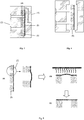
- the regions of the plastic film which are not to be back-injected are preferably covered in step A) with one or more punches or slides so that one or more partial surfaces of the plastic film are not back-injected.
- the non-back-injected (n) partial surface (s) of the plastic film are (are) completely surrounded by back-injected partial surfaces of the plastic film after injection molding.
- a plurality of non-contiguous partial surfaces of the plastic film are not back-injected in the step A) and the non-back-injected partial surfaces of the plastic film are completely surrounded by back-injected partial surfaces of the plastic film.
- the back molding in step A) by means of windowing.
- This window technique in which the regions of the plastic film which are not to be back-injected in step A) are covered with one or more punches or slides, so that one or more partial surfaces of the plastic film are not back-injected, is known to the person skilled in the art.
- the injection molding of the plastic film is carried out by methods known in the art.
- a plastic film is inserted into a first half of an open injection mold and then the tool can be closed by a second half of the tool is mounted on the first half, so that between the film and the second mold half a cavity (gap, cavity) is formed, and then the plastic film are back-injected with thermoplastic in the tool by the thermoplastic material is introduced into the cavity.
- the punches or slides used to cover the areas not to be injected can preferably be mounted on the second half of the tool and cover the areas to be kept clear when the tool is closed.
- step A this can be inserted either with the printed side toward the tool wall or with the printed side facing away from the tool wall in the first mold half.
- Step C) can then take place after opening the tool in one of the two tool halves.
- the plastic molded part can also be removed from the tool after cooling in step B), and step C) can take place outside the tool.
- the plastic molding can also be removed from the tool before reaching the intended complete cooling and the cooling can be completed outside of the tool. This approach may, for example, have the advantage that in certain embodiments the present invention, a sufficient shrinkage of the molding obtained in step A) with the remaining mold temperature in step B) can not be achieved or not fast enough.
- the cooling of the plastic molding obtained in step A) in step B) before re-heating in step C) is preferably carried out at a temperature at which the complete shrinkage and / or complete shrinkage of the obtained under step A) plastic molding.
- the cooling of the plastic molding obtained in step A) in step B) before re-heating in step C) to a temperature of below 60 ° C, more preferably below 50 ° C, most preferably below 40 ° C. It is further preferred that the temperature to which the plastic molded article obtained in step A) does not subcool in step B) before re-heating in step C), i. is not cooled to a temperature below 0 ° C, preferably not to a temperature below 10 ° C.
- the plastic film is preferably at least partially transparent or translucent in the non-back-injected areas, i. translucent to allow backlighting on these transparent or translucent areas.
- the plastic film can be at least partially transparent to light in the visible wavelength range in the non-back-injected areas to 100%, preferably the plastic film in the non-back-injected areas at least partially translucent.
- Translucency within the scope of the invention is a transmission of light in the visible wavelength range of more than 20% and less than 100%, preferably more than 50% and less than 100%, particularly preferably more than 70% and less than 100%. to understand.
- the visible wavelength range of the light extends over the wavelength range of 380 to 780 nm.
- the light transmission can be measured with a Hunter UltraScanPRO with a diffuse / 8 ° geometry.
- plastic film is in the non-back-injected areas at least part of the surface neither transparent nor translucent, for example, control element, e.g. capacitive circuits or mechanical switches to access.
- Plastic moldings produced by the process according to the invention are suitable, for example, for use in electronic devices, household appliances, mobile phones, computers, for example for computer keyboards, in the vehicle interior, such as in the automotive interior and in the aircraft industry. or rail vehicle interior etc .. Plastic moldings produced by the process according to the invention can be used in these applications, for example, as controls that should be accessible to the user in the dark by backlighting.
- the glass transition temperature T g was determined in each case by means of differential scanning calorimetry (DSC) according to standard ISO 113557-2 at a heating rate of 10 K / min, during the second heating and with definition of T g as the midpoint temperature (tangent method).
- DSC differential scanning calorimetry
- the polycarbonate films were subsequently back-molded in an injection molding with a thermoplastic polycarbonate (Makrolon ® 2405).
- the polycarbonate Polybuthylentherephthalat blend film was in an injection molding with a thermoplastic polycarbonate / ABS blend (Bayblend T65 ®) injected behind.
- the tests were carried out on an Arburg Allrounder 570 C injection molding machine with a clamping force of 200 tons.
- a plate tool with a wall thickness of 2.5 mm with breakthroughs of different shapes (partly round openings with diameters of 10 to 30 mm, some rectangular and square openings with edge lengths of 10 to 30 mm) was used.
- the melt temperature was 280 ° C and the mold temperature was 60 ° C.
- the filling time was measured for the Makrolon ® 2405 and ® Bayblend T65 of about 2.8 sec.
- the method of windowing was used. For this stamp fumbled when closing the tool exactly to the areas to be kept free the foil. In the back injection was so successfully avoided that plastic melt could reach these areas.
- the back-molded part was cooled to room temperature (23 ° C). In all four cases (polycarbonate films with a film thickness of 150 ⁇ m, 175 ⁇ m, 200 ⁇ m and polybuthylene terephthalate blend film with a film thickness of 375 ⁇ m), bumps in the film were produced at the non-back-injected areas.
- the molding was removed from the tool and the film areas, which have not been back-injected with plastic, reheated briefly with a commercial IR ceramic emitter and alternatively with a hot air dryer.
- the re-heating for the polycarbonate films was carried out at a temperature of 175 ° C and for the polybuthylene terephthalate blend film to 155 ° C.
- the temperature of the films was measured using a commercial line pyrometer from Bartec Messtechnik and sensors, the distance between the camera and the film surface being 56 cm.
- the heating time was varied for the experiments within the range of 0.5 to 5 seconds. Whether a long heating time with lower radiator output, or a short heating time with high performance was used, showed no difference in the final result. The components had no bumps after re-heating and cooling.
Landscapes
- Engineering & Computer Science (AREA)
- Manufacturing & Machinery (AREA)
- Mechanical Engineering (AREA)
- Physics & Mathematics (AREA)
- Thermal Sciences (AREA)
- Injection Moulding Of Plastics Or The Like (AREA)
- Moulds For Moulding Plastics Or The Like (AREA)
- Casting Or Compression Moulding Of Plastics Or The Like (AREA)
- Laminated Bodies (AREA)
Priority Applications (1)
| Application Number | Priority Date | Filing Date | Title |
|---|---|---|---|
| EP12155209A EP2489493A2 (fr) | 2011-02-17 | 2012-02-13 | Procédé d'équilibrage d'oscillations partiel pour des pièces de formage en matière synthétique |
Applications Claiming Priority (2)
| Application Number | Priority Date | Filing Date | Title |
|---|---|---|---|
| EP11154822A EP2489492A1 (fr) | 2011-02-17 | 2011-02-17 | Procédé d'équilibrage d'oscillations partiel dans des pièces de formage en matière synthétique |
| EP12155209A EP2489493A2 (fr) | 2011-02-17 | 2012-02-13 | Procédé d'équilibrage d'oscillations partiel pour des pièces de formage en matière synthétique |
Publications (1)
| Publication Number | Publication Date |
|---|---|
| EP2489493A2 true EP2489493A2 (fr) | 2012-08-22 |
Family
ID=44167973
Family Applications (2)
| Application Number | Title | Priority Date | Filing Date |
|---|---|---|---|
| EP11154822A Withdrawn EP2489492A1 (fr) | 2011-02-17 | 2011-02-17 | Procédé d'équilibrage d'oscillations partiel dans des pièces de formage en matière synthétique |
| EP12155209A Withdrawn EP2489493A2 (fr) | 2011-02-17 | 2012-02-13 | Procédé d'équilibrage d'oscillations partiel pour des pièces de formage en matière synthétique |
Family Applications Before (1)
| Application Number | Title | Priority Date | Filing Date |
|---|---|---|---|
| EP11154822A Withdrawn EP2489492A1 (fr) | 2011-02-17 | 2011-02-17 | Procédé d'équilibrage d'oscillations partiel dans des pièces de formage en matière synthétique |
Country Status (7)
| Country | Link |
|---|---|
| US (1) | US20120213977A1 (fr) |
| EP (2) | EP2489492A1 (fr) |
| JP (1) | JP2012171355A (fr) |
| KR (1) | KR20120102507A (fr) |
| CN (1) | CN102642267A (fr) |
| BR (1) | BR102012003689A2 (fr) |
| RU (1) | RU2012105417A (fr) |
Families Citing this family (4)
| Publication number | Priority date | Publication date | Assignee | Title |
|---|---|---|---|---|
| DE102011102830B4 (de) * | 2011-05-30 | 2014-11-13 | Hbw-Gubesch Kunststoff-Engineering Gmbh | Herstellung von foliendekorierten Kunststoffteilen mit Durchbrüchen oder tiefen Einschnitten mittels IMD-Spritzguss |
| JP7314612B2 (ja) * | 2019-05-14 | 2023-07-26 | 富士電機株式会社 | 樹脂成型物および樹脂成型物の製造方法 |
| CN111361099B (zh) * | 2020-04-16 | 2025-07-22 | 佛山市南海华达高木模具有限公司 | 一种收缩补偿滑块结构 |
| CN112550932A (zh) * | 2020-12-02 | 2021-03-26 | 卓高泰(广州)材料科技有限公司 | 一种双色透明盖及其模具 |
Citations (7)
| Publication number | Priority date | Publication date | Assignee | Title |
|---|---|---|---|---|
| DE1900270A1 (de) | 1968-01-04 | 1969-11-06 | Rhodiaceta | Neue thermoplastische Formmassen |
| DE2407674A1 (de) | 1973-03-30 | 1974-10-10 | Tokyo Kosei Kaken Co | Fahrbare vorrichtung zum schleifen und reinigen von boeden |
| DE2407776A1 (de) | 1974-02-19 | 1975-09-04 | Licentia Gmbh | Schaltung zur regelung der betriebsspannung fuer die transistor-zeilenendstufe eines fernsehempfaengers |
| DE2715932A1 (de) | 1977-04-09 | 1978-10-19 | Bayer Ag | Schnellkristallisierende poly(aethylen/alkylen)-terephthalate |
| EP0371425A2 (fr) | 1988-12-01 | 1990-06-06 | Curt Niebling | Procédé de fabrication de pièces embouties en matière plastique |
| WO2009043539A2 (fr) | 2007-09-28 | 2009-04-09 | Bayer Materialscience Ag | Procédé de réalisation d'une pièce mince emboutie en matière thermoplastique |
| WO2009138217A1 (fr) | 2008-05-14 | 2009-11-19 | Bayer Materialscience Ag | Matériau stratifié revêtu d'une encre d'impression ou d'une laque d'impression radiodurcissable et pièce moulée |
Family Cites Families (4)
| Publication number | Priority date | Publication date | Assignee | Title |
|---|---|---|---|---|
| DE3302789C2 (de) * | 1982-01-29 | 1986-03-06 | Citizen Watch Co., Ltd., Tokio/Tokyo | Uhrenarmband und Verfahren zu seiner Herstellung |
| BE1002368A3 (nl) * | 1988-08-16 | 1991-01-15 | Confect Schockaert Bv Met Bepe | Werkwijze voor het bevestigen van een gesp aan een riem. |
| US7655163B2 (en) * | 2007-05-09 | 2010-02-02 | Sanwa Screen Co., Ltd. | Manufacturing method of film insert molded article |
| CN101100101B (zh) * | 2007-07-31 | 2010-06-09 | 中兴通讯股份有限公司 | 一种表面薄膜消鼓平整的注塑方法 |
-
2011
- 2011-02-17 EP EP11154822A patent/EP2489492A1/fr not_active Withdrawn
-
2012
- 2012-02-07 US US13/367,502 patent/US20120213977A1/en not_active Abandoned
- 2012-02-13 EP EP12155209A patent/EP2489493A2/fr not_active Withdrawn
- 2012-02-16 RU RU2012105417/05A patent/RU2012105417A/ru not_active Application Discontinuation
- 2012-02-16 KR KR1020120015678A patent/KR20120102507A/ko not_active Withdrawn
- 2012-02-16 JP JP2012031714A patent/JP2012171355A/ja active Pending
- 2012-02-17 CN CN2012100362709A patent/CN102642267A/zh active Pending
- 2012-02-17 BR BRBR102012003689-4A patent/BR102012003689A2/pt not_active Application Discontinuation
Patent Citations (8)
| Publication number | Priority date | Publication date | Assignee | Title |
|---|---|---|---|---|
| DE1900270A1 (de) | 1968-01-04 | 1969-11-06 | Rhodiaceta | Neue thermoplastische Formmassen |
| US3692744A (en) | 1968-01-04 | 1972-09-19 | Rhodiaceta | Injection molded branched polyesters |
| DE2407674A1 (de) | 1973-03-30 | 1974-10-10 | Tokyo Kosei Kaken Co | Fahrbare vorrichtung zum schleifen und reinigen von boeden |
| DE2407776A1 (de) | 1974-02-19 | 1975-09-04 | Licentia Gmbh | Schaltung zur regelung der betriebsspannung fuer die transistor-zeilenendstufe eines fernsehempfaengers |
| DE2715932A1 (de) | 1977-04-09 | 1978-10-19 | Bayer Ag | Schnellkristallisierende poly(aethylen/alkylen)-terephthalate |
| EP0371425A2 (fr) | 1988-12-01 | 1990-06-06 | Curt Niebling | Procédé de fabrication de pièces embouties en matière plastique |
| WO2009043539A2 (fr) | 2007-09-28 | 2009-04-09 | Bayer Materialscience Ag | Procédé de réalisation d'une pièce mince emboutie en matière thermoplastique |
| WO2009138217A1 (fr) | 2008-05-14 | 2009-11-19 | Bayer Materialscience Ag | Matériau stratifié revêtu d'une encre d'impression ou d'une laque d'impression radiodurcissable et pièce moulée |
Non-Patent Citations (4)
| Title |
|---|
| "Kunststoff-Handbuch", vol. VIII, 1973, KARL-HANSER-VERLAG, pages: 695 FF |
| D. FREITAG ET AL.: "Encyclopedia of Polymer Science and Engineering", vol. 11, 1988, article "Polycarbonates", pages: 648 - 718 |
| DRES. U. GRIGO ET AL.: "Kunststoff-Handbuch, Band 3/1, Polycarbonate, Polyacetale, Polyester, Celluloseester", vol. 3/1, 1992, CARL HANSER VERLAG, article "Polycarbonate", pages: 117 - 299 |
| SCHNELL: "Polymer Reviews", vol. 9, 1964, INTERSCIENCE PUBLISHERS, article "Chemistry and Physics of Polycarbonates" |
Also Published As
| Publication number | Publication date |
|---|---|
| RU2012105417A (ru) | 2013-08-27 |
| CN102642267A (zh) | 2012-08-22 |
| EP2489492A1 (fr) | 2012-08-22 |
| KR20120102507A (ko) | 2012-09-18 |
| BR102012003689A2 (pt) | 2013-07-30 |
| JP2012171355A (ja) | 2012-09-10 |
| US20120213977A1 (en) | 2012-08-23 |
Similar Documents
| Publication | Publication Date | Title |
|---|---|---|
| EP2197656B1 (fr) | Procédé de réalisation d'une pièce mince emboutie en matière thermoplastique | |
| US8945704B2 (en) | Multi-layer film, decorative molding film and molded body | |
| EP2172336A1 (fr) | Caractéristiques de sécurité protégées contre la falsification dans des documents de sécurité ou de valeur | |
| EP2683551B1 (fr) | Feuille transparente en matière plastique pouvant être traitée par électrodéposition, destinée à être partiellement traitée par électrodéposition | |
| EP2489493A2 (fr) | Procédé d'équilibrage d'oscillations partiel pour des pièces de formage en matière synthétique | |
| EP3890971B1 (fr) | Feuilles en matière plastique à température de ramollissement vicat plus élevée dans les structures stratifiées | |
| WO2010091796A1 (fr) | Procédé amélioré de production d'un composite multicouche laminé | |
| EP2804763B1 (fr) | Feuille en matière synthétique destinée à l'impression à l'aide d'une diffusion de colorant par transfert thermique | |
| EP3501819A1 (fr) | Feuilles en matière plastique pour document d'id à luminosité des hologrammes estampés améliorée | |
| EP2393657A1 (fr) | Composite en feuille multicouches, comportant une couche en polycarbonate | |
| WO2011076717A1 (fr) | Procédé pour fabriquer un ensemble de feuilles déformé à base de plastique thermoplastique | |
| WO2020099344A1 (fr) | Films plastiques présentant une opacité élevée et une faible transparence pour des documents d'identité pourvus d'une fenêtre transparente | |
| WO2011083013A2 (fr) | Procédé pour la fabrication d'une partie de feuille emboutie en matière plastique thermoplastique | |
| EP2168783A1 (fr) | Utilisation d'un film plastique dans l'impression laser couleur | |
| JP2003253111A (ja) | 樹脂組成物、積層成形品、およびリサイクル方法 | |
| DE102022105839A1 (de) | Verfahren zum Herstellen eines Kunststoff-Formteils | |
| EP2459378A1 (fr) | Feuille de polyester dimensionnellement stable, et support de données comportant la feuille de polyester | |
| EP4074718A1 (fr) | Stabilisateurs pour polymères | |
| EP2455228A1 (fr) | Document de sécurité et/ou de valeur contenant un convertisseur électromécanique | |
| EP3623148A1 (fr) | Procédé de fabrication d'un laminé comportant des composants électroniques et / ou des unités fonctionnelles |
Legal Events
| Date | Code | Title | Description |
|---|---|---|---|
| PUAI | Public reference made under article 153(3) epc to a published international application that has entered the european phase |
Free format text: ORIGINAL CODE: 0009012 |
|
| AK | Designated contracting states |
Kind code of ref document: A2 Designated state(s): AL AT BE BG CH CY CZ DE DK EE ES FI FR GB GR HR HU IE IS IT LI LT LU LV MC MK MT NL NO PL PT RO RS SE SI SK SM TR |
|
| AX | Request for extension of the european patent |
Extension state: BA ME |
|
| RAP1 | Party data changed (applicant data changed or rights of an application transferred) |
Owner name: BAYER INTELLECTUAL PROPERTY GMBH |
|
| STAA | Information on the status of an ep patent application or granted ep patent |
Free format text: STATUS: THE APPLICATION HAS BEEN WITHDRAWN |
|
| 18W | Application withdrawn |
Effective date: 20141120 |