EP2198511B1 - Motorsteuerung mit hallsensor-fehlausrichtungskompensation - Google Patents
Motorsteuerung mit hallsensor-fehlausrichtungskompensation Download PDFInfo
- Publication number
- EP2198511B1 EP2198511B1 EP08769508A EP08769508A EP2198511B1 EP 2198511 B1 EP2198511 B1 EP 2198511B1 EP 08769508 A EP08769508 A EP 08769508A EP 08769508 A EP08769508 A EP 08769508A EP 2198511 B1 EP2198511 B1 EP 2198511B1
- Authority
- EP
- European Patent Office
- Prior art keywords
- motor
- windings
- commutation
- commutation state
- state
- Prior art date
- Legal status (The legal status is an assumption and is not a legal conclusion. Google has not performed a legal analysis and makes no representation as to the accuracy of the status listed.)
- Not-in-force
Links
- 238000004804 winding Methods 0.000 claims abstract description 60
- 230000005355 Hall effect Effects 0.000 claims abstract description 23
- 238000000034 method Methods 0.000 claims abstract description 17
- 230000003111 delayed effect Effects 0.000 claims abstract description 16
- 238000012544 monitoring process Methods 0.000 claims 2
- 230000009471 action Effects 0.000 abstract description 4
- 230000007704 transition Effects 0.000 description 8
- 238000010586 diagram Methods 0.000 description 6
- 230000008569 process Effects 0.000 description 4
- 230000001419 dependent effect Effects 0.000 description 3
- 238000004519 manufacturing process Methods 0.000 description 2
- 238000011084 recovery Methods 0.000 description 2
- 238000012163 sequencing technique Methods 0.000 description 2
- 230000009286 beneficial effect Effects 0.000 description 1
- 230000001934 delay Effects 0.000 description 1
- 230000003292 diminished effect Effects 0.000 description 1
- 230000000694 effects Effects 0.000 description 1
- 230000003993 interaction Effects 0.000 description 1
Images



Classifications
-
- H—ELECTRICITY
- H02—GENERATION; CONVERSION OR DISTRIBUTION OF ELECTRIC POWER
- H02P—CONTROL OR REGULATION OF ELECTRIC MOTORS, ELECTRIC GENERATORS OR DYNAMO-ELECTRIC CONVERTERS; CONTROLLING TRANSFORMERS, REACTORS OR CHOKE COILS
- H02P6/00—Arrangements for controlling synchronous motors or other dynamo-electric motors using electronic commutation dependent on the rotor position; Electronic commutators therefor
- H02P6/14—Electronic commutators
- H02P6/16—Circuit arrangements for detecting position
-
- H—ELECTRICITY
- H02—GENERATION; CONVERSION OR DISTRIBUTION OF ELECTRIC POWER
- H02P—CONTROL OR REGULATION OF ELECTRIC MOTORS, ELECTRIC GENERATORS OR DYNAMO-ELECTRIC CONVERTERS; CONTROLLING TRANSFORMERS, REACTORS OR CHOKE COILS
- H02P29/00—Arrangements for regulating or controlling electric motors, appropriate for both AC and DC motors
- H02P29/02—Providing protection against overload without automatic interruption of supply
- H02P29/032—Preventing damage to the motor, e.g. setting individual current limits for different drive conditions
Definitions
- BLDC brushless direct-current
- motor rotation is caused by electronic switching or "commutation" of drive current among a plurality of motor windings.
- the commutation induces a rotating component to the overall magnetic field associated with the windings, and the interaction of this rotating magnetic field component with the rotor's permanent magnets which causes rotation of the rotor.
- one common BLDC configuration employs three windings offset from each other by 120 degrees of electrical phase.
- Commutation can be performed in many different ways.
- a set of motor position sensors such as Hall-effect magnetic sensors are arranged about the motor rotational axis with a precise spacing. As the rotor rotates, the output of each Hall-effect sensor switches in a binary fashion. The collective outputs of the sensors are used to control commutation.
- three sensors offset from each other by nominally 120 mechanical degrees are used.
- Each of six distinct sets of the three binary outputs of the sensors maps directly to a corresponding commutation state in which a particular pair of the motor windings is driven with current with a particular polarity. Thus commutation occurs precisely at the time that the binary output from one of the sensors switches from one binary state to the other.
- the sensors are located such that this transition occurs exactly midway between two successive peaks of a torque characteristic of the motor, so that the value of the torque at this "valley" location is as high as possible.
- This ideal configuration provides the highest minimum torque value which may be especially needed to maintain proper operation under high load conditions.
- Misalignment of the motor position sensors in a motor system can cause commutation to be later or earlier than the ideal, causing the torque to be reduced below the ideal minimum torque that is available with perfect alignment. Under high load conditions, the motor could stall. It is desirable to quickly detect and overcome such a stall, i.e., resume normal motor rotation, if possible.
- Boe et al. The technique of Boe et al. is applied to the case of an impending stall with accompanying saturation, which is overcome by switching to the next successive commutation state.
- This technique cannot be used to address sensor misalignment which erroneously shifts commutation in an unknown direction (either early or late). If the sensors are misaligned such that commutation occurs earlier than under ideal conditions, then merely switching to the next successive commutation state as in Boe et al. will not result in the desired increased torque, but rather an even further diminished torque that will likely not overcome the stall.
- the disclosed technique is directed to recovering from stalls caused by the misalignment of motor position sensors (such as Hall-effect sensors) where the direction of such misalignment is not known a priori.
- a disclosed motor controller (1) provides motor drive current to the windings of a motor based on the sensor signals such that sets of the windings are driven in a normal commutation sequence corresponding to a sequence of states of the sensor signals, and (2) monitors for occurrence of a motor stall condition.
- the motor controller Upon detecting the motor stall condition with the sensor signals in a given state that in the normal operating mode results in driving the windings according to a corresponding given commutation state, the motor controller (1) in a first driving step, momentarily drives the windings according to one of an advanced commutation state and a delayed commutation state each adjacent to the given commutation state in the normal commutation sequence, (2) determines whether the motor stall condition persists after the first driving step, and (3) if the stall condition persists after the first driving step then in a second driving step momentarily drives the windings according to the other of the advanced commutation state and the delayed commutation state.
- the controller attempts operation at both preceding and succeeding portions of the torque characteristic, one of which is the more effective portion for increasing torque depending on the direction of misalignment of the sensors.
- the controller attempts operation at both preceding and succeeding portions of the torque characteristic, one of which is the more effective portion for increasing torque depending on the direction of misalignment of the sensors.
- FIG. 1 shows a system having a motor assembly 10 coupled by a wiring harness 12 to a controller 14.
- the motor assembly 10 includes a motor 16 such as a brushless DC motor, and a sensor assembly 18 affixed to one end of the motor 16.
- One end of the wiring harness 12 terminates on the sensor assembly 18.
- the controller 14 controls the operation of the motor 10, specifically its rotational position and/or speed depending on the application.
- the motor 16 is part of an electromagnetic actuator utilized to control the position of a mechanical component, such as in an aircraft.
- the controller 14 monitors the rotational position of the motor 14 via
- Hall-effect sensors located on the sensor assembly 18 and controls the flow of current to the windings of the motor 16 to achieve a desired motor position and/or speed for a desired actuator movement.
- Different types of motor control arrangements and techniques may be utilized in different embodiments, including specific circuitry for controlling winding currents.
- the present description is primarily concerned with recovering from a motor stall condition that is caused in part by inaccurate motor position information in turn caused by misalignment of the position sensors on the sensor assembly 18.
- Figure 2 depicts operation of the motor 16 under normal operating conditions.
- One electrical rotation from 0 to 2 ⁇ radians is shown.
- the number of electrical rotations per mechanical rotation is dependent on the number of permanent magnet pole pairs in a particular motor design.
- the motor is assumed to have three rotor phase windings labeled A, B and C.
- the windings are driven pair-wise in operation through 6 commutation states or commutation intervals during each revolution as generally known in the art.
- the sequence of commutation states also called a "commutation sequence” is shown as AB, AC, BC, BA, CA and CB in the illustrated embodiment.
- the timing of the commutation sequence is determined by the motor rotational position as indicated by the outputs of the Hall-effect sensors, which are indicated by the sequence of "Hall states" 1 through 6.
- Hall states 1-6 may correspond to different combinations of binary states of three Hall-effect sensors arranged at intervals of 2 ⁇ /3 radians about the rotational axis, in one embodiment.
- Time in Figure 2 is indicated by fractions of the motor rotation period T.
- FIG. 2 Also shown in Figure 2 is a plot of the motor torque, which has the characteristic of a sum of rectified portions of the three phase voltages (back EMF).
- the torque exhibits ripple with a magnitude shown as a "torque valley" (TV) of 13.4%.
- T MIN minimum torque value
- T MAX maximum torque value
- the controller 14 utilizes the position information from the Hall-effect sensors in order to effect commutation of the motor windings to maintain motor rotation.
- the controller 14 drives the winding pair AB.
- the controller 14 switches or "commutates" the driving current to windings AC, etc.
- the driving of the motor windings is determined by the motor position information as indicated by the Hall-effect sensors.
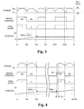
- Figure 3 illustrates an undesirable operating condition that can occur when one of the Hall-effect sensors is misaligned such that its output exhibits a delay with respect to the output from a properly aligned sensor.
- the transitions into Hall states 1 and 2 exhibit normal timing, but the transition from state 2 to state 3 is delayed. Accordingly, the winding pair AC is driven beyond the normal commutation point at T/3, such that the motor torque is reduced below that ideal minimum shown in Figure 3 .
- the torque valley TV is about 29.4%, indicating that torque has fallen to about 70.6% of peak. In such a situation, if the motor load is sufficiently high then the motor can stall because it does not have sufficient torque to drive the load.
- Such a stall is shown in Figure 3 - it occurs at a time T/3+ just after the time T/3. Due to the stall, the Hall state remains at 2, and thus the controller 14 continues to drive winding pair AC and the torque remains at its low level.
- the dotted lines in Figure 3 indicate the patterns of the respective signals that would be expected if the stall had not occurred.
- Figure 4 illustrates a technique utilized to recover from a situation of the type shown in Figure 3 . It is assumed that the motor stall at time T/3+ is detected by some means, such as circuitry which detects that no movement of the motor has occurred for a period of time under conditions in which movement is expected (i.e., movement is being commanded by higher-level circuitry within the controller 14). Typically such a stall condition will be accompanied by application of an abnormally high driving current to the windings which can be detected within the controller 14. At the time that such a stall is detected, which is shown as "ADV" in Figure 4 , the controller 14 momentarily advances the commutation state of the windings.
- some means such as circuitry which detects that no movement of the motor has occurred for a period of time under conditions in which movement is expected (i.e., movement is being commanded by higher-level circuitry within the controller 14).
- Typically such a stall condition will be accompanied by application of an abnormally high driving current to the windings which can
- T ADV duration of this operation.
- the duration of T ADV will be highly dependent on a variety of factors, including the dynamic rotational characteristics of the motor 14 and the degree of misalignment of the Hall-effect sensors.
- a value of T ADV in the range of 10-12 milliseconds may be effective.
- Figures 5 and 6 illustrate another undesirable operating condition that can occur when one of the Hall-effect sensors is misaligned such that its output exhibits an advance with respect to the output from a properly aligned sensor.
- the transitions into Hall states 1 and 2 exhibit normal timing, but the transition from state 2 to state 3 is advanced or early. Accordingly, the winding pair BC becomes driven prematurely, before the normal commutation point at T/3, such that the motor torque is abruptly reduced below the ideal minimum shown in Figure 3 .
- the torque valley TV is again about 29.4%. In such a situation, if the motor load is sufficiently high then the motor can stall because it does not have sufficient torque to drive the load.
- Such a stall is shown in Figure 5 - it occurs at a time T/3- just prior to T/3. Due to the stall, the Hall state remains at 3, and thus the controller 14 continues to drive winding pair BC and the torque remains at its low level.
- the dotted lines in Figure 5 indicate the patterns of the respective signals that would be expected if the stall had not occurred.
- Figure 6 illustrates a technique utilized to recover from a situation of the type shown in Figure 5 . It is assumed that the motor stall at time T/3- is detected by some means such as discussed above. At the time that such a stall is detected, which is shown as "DLY" in Figure 6 , the controller 14 momentarily delays the commutation state of the windings, i.e., it momentarily drives the winding pair that precedes the currently driven winding pair in the commutation sequence. In the particular situation of Figure 6 , drive current is momentarily applied to the winding pair AC. As shown, this action moves the motor operation to a much higher point on the torque curve. If the torque increase is sufficient, the motor will begin rotating again and normal operation can resume, such as shown in Figure 6 . In this case, the Hall state will resume its normal sequencing beginning at Hall state 3 and the controller 14 resumes the normal pattern of driving the windings starting with the corresponding winding pair BC.
- DLY the controller 14 momentarily delays the commutation state of the wind
- T DLY the duration of T DLY will be highly dependent on a variety of factors, including the dynamic rotational characteristics of the motor 14 and the degree of misalignment of the Hall-effect sensors, and it may or may not be different from T ADV .
- the controller 14 may not know whether the stall is caused by misalignment of the Hall-effect sensors, and if so whether the sensors are misaligned in one rotational direction so as to cause a late commutation (as shown in Figures 3 and 4 ) or in the other rotational direction so as to cause an early commutation (as shown in Figures 5 and 6 ). It will be appreciated by those skilled in the art that the advance technique of Figure 4 will not recover from the stall condition of Figure 5 caused by early commutation, and likewise the delay technique of Figure 6 will not recover from the stall condition of Figure 3 caused by late commutation. In either case, the torque applied during the momentary operation would actually be reduced rather than increased. Thus generally a motor system can only employ a single one of the techniques of Figures 4 or 6 to overcome sensor misalignment if the direction of misalignment of the Hall-effect sensors is known.
- FIG 7 shows a process that can be utilized when the direction of misalignment of the Hall-effect sensors is unknown, which may be the case, for example, for normal manufacturing tolerances.
- Step 20 indicates operation in the normal operating mode such as illustrated by Figure 2 and discussed above.
- a motor stall condition is detected, causing the process to proceed to step 24 which is a momentary advance operation such as described above with reference to Figure 4 .
- step 26 it is determined whether the stall condition persists. If not (i.e., the motor has resumed rotating), then the normal operating mode is resumed at 20. This operation might occur, for example, if the stall is due to sensor misalignment that causes delayed commutation such as shown in Figures 3 and 4 .
- step 28 a momentary delay operation such as described above with reference to Figure 6 is performed. If the stall condition is due to sensor misalignment that causes early commutation such as shown in Figures 5 and 6 , then the operation at step 28 may induce the motor 14 to resume rotating.
- one alternative to the process of Figure 7 is to simply reverse the order of the advance and delay steps 24 and 28, i.e., to first delay commutation and then, if the stall condition persists at step 26, advance it.
- One order or the other may be more beneficial depending on the characteristics of the motor system and any known tendency of the sensor misalignment. If in a majority of cases the sensor misalignment results in delayed commutation such as shown in Figures 3 and 4 , then the order shown in Figure 7 might be most effective. If in a majority of cases the sensor misalignment results in early commutation such as shown in Figures 5 and 6 , then the opposite order (delay then advance) might be better to use. The order could be predetermined by the system design or it could be selectable either at manufacturing time or even by a user.
Landscapes
- Engineering & Computer Science (AREA)
- Power Engineering (AREA)
- Control Of Motors That Do Not Use Commutators (AREA)
Claims (6)
- Verfahren zum Ausgleichen einer Fehlausrichtung von Halleffektsensoren, die Sensorsignale erzeugen, die eine Motorpositionsinformation bereitstellen, um eine Kommutierung eines Motorantriebstrom durch Wicklungen eines Motors zu steuern, mit den Schritten:in einer normalen Betriebsart (20),
Bereitstellen eines Motorantriebstroms an die Wicklungen basierend auf den Sensorsignalen, so dass Sätze der Wicklungen in einer normalen Kommutierungssequenz entsprechend einer Sequenz von Zuständen der Sensorsignale angesteuert werden; und
Überwachen eines Auftretens eines Motorverzögerungszustandes (22);
dadurch gekennzeichnet, dass eine Detektion des Motorverzögerungszustandes (22) mit den Sensorsignalen in einem gegebenen Zustand in dem normalen Betriebsmodus (20) zum Ansteuern der Wicklungen entsprechend einem übereinstimmenden gegebenen Kommutierungszustand führt,in einem ersten Antriebsschritt (24) die Wicklungen entsprechend einem erweiterten Kommutierungszustand oder einem verzögerten Kommutierungszustand jeweils benachbart zu dem gegebenen Kommutierungszustand in der normalen Kommutierungssequenz momentan angesteuert werden;Bestimmen, ob nach dem ersten Antriebsschritt (24) der Motorverzögerungszustand bestehen bleibt (26); undwenn der Verzögerungszustand nach dem ersten Antriebsschritt (24) bestehen bleibt, dann werden in einem zweiten Antriebsschritt (28) die Wicklungen entsprechend dem anderen des erweiterten Kommutierungszustandes und dem verzögerten Kommutierungszustand momentan angetrieben. - Verfahren nach Anspruch 1,
wobei in dem ersten Antriebsschritt (24) die Wicklungen entsprechend dem erweiterten Kommutierungszustand angesteuert und in dem zweiten Antriebsschritt (28) die Wicklungen entsprechend dem verzögerten Kommutierungszustand angesteuert werden. - Verfahren nach Anspruch 1,
wobei in dem ersten Antriebsschritt die Wicklungen entsprechend dem verzögerten Kommutierungszustand angesteuert und in dem zweiten Antriebsschritt die Wicklungen entsprechend dem erweiterten Kommutierungszustand angesteuert werden. - Motorsystem mit:einem Motor (16) mit Halleffektsensoren, die Sensorsignale zum Bereitstellen von Motorpositionsinformation erzeugen; undeinem Motorregler (14) gekoppelt mit dem Motor (16),wobei der Regler (14) dazu ausgestaltet ist, eine Fehlausrichtung der Halleffektsensoren beim Steuern von Kommutierung eines Motorantriebsstroms durch die Wicklungen eines Motors auszugleichen durch:in einer normalen Betriebsart (20),
Bereitstellen eines Motorantriebstroms an die Wicklungen basierend auf den Sensorsignalen , so dass Sätze der Wicklungen in einer normalen Kommutierungssequenz entsprechend einer Sequenz von Zuständen der Sensorsignale angesteuert werden; und
Überwachen eines Auftretens eines Motorverzögerungszustandes (22);
dadurch gekennzeichnet, dass eine Detektion des Motorverzögerungszustandes (22) mit den Sensorsignalen in einem gegebenen Zustand in dem normalen Betriebsmodus (20) zum Ansteuern der Wicklungen entsprechend einem übereinstimmenden gegebenen Kommutierungszustand führt,in einem ersten Antriebsschritt (24) die Wicklungen entsprechend einem erweiterten Kommutierungszustand oder einem verzögerten Kommutierungszustand jeweils benachbart zu dem gegebenen Kommutierungszustand in der normalen Kommutierungssequenz momentan angesteuert werden;Bestimmen, ob nach dem ersten Antriebsschritt (24) der Motorverzögerungszustand bestehen bleibt (26); undwenn der Verzögerungszustand nach dem ersten Antriebsschritt (24) bestehen bleibt, dann werden in einem zweiten Antriebsschritt (28) die Wicklungen entsprechend dem anderen des erweiterten Kommutierungszustandes und dem verzögerten Kommutierungszustand momentan angetrieben. - Motorsystem nach Anspruch 4,
wobei in dem ersten Antriebsschritt (24) der Motorregler dazu ausgestaltet ist, Wicklungen entsprechend dem erweiterten Kommutierungszustand und in dem zweiten Antriebsschritt (28) der Motorregler dazu ausgestaltet ist, die Wicklungen entsprechend dem verzögerten Kommutierungszustand anzutreiben. - Motorsystem nach Anspruch 4,
wobei in dem ersten Antriebsschritt der Motorregler dazu ausgestaltet ist, Wicklungen entsprechend dem verzögerten Kommutierungszustand und in dem zweiten Antriebsschritt der Motorregler dazu ausgestaltet ist, Wicklungen entsprechend dem erweiterten Kommutierungszustand anzutreiben.
Applications Claiming Priority (2)
| Application Number | Priority Date | Filing Date | Title |
|---|---|---|---|
| US11/850,999 US7808200B2 (en) | 2007-09-06 | 2007-09-06 | Motor controller with hall sensor misalignment compensation |
| PCT/US2008/064054 WO2009032365A1 (en) | 2007-09-06 | 2008-05-19 | Motor controller with hall sensor misalignment compensation |
Publications (2)
| Publication Number | Publication Date |
|---|---|
| EP2198511A1 EP2198511A1 (de) | 2010-06-23 |
| EP2198511B1 true EP2198511B1 (de) | 2011-08-31 |
Family
ID=39638897
Family Applications (1)
| Application Number | Title | Priority Date | Filing Date |
|---|---|---|---|
| EP08769508A Not-in-force EP2198511B1 (de) | 2007-09-06 | 2008-05-19 | Motorsteuerung mit hallsensor-fehlausrichtungskompensation |
Country Status (4)
| Country | Link |
|---|---|
| US (1) | US7808200B2 (de) |
| EP (1) | EP2198511B1 (de) |
| AT (1) | ATE522975T1 (de) |
| WO (1) | WO2009032365A1 (de) |
Families Citing this family (19)
| Publication number | Priority date | Publication date | Assignee | Title |
|---|---|---|---|---|
| US8577811B2 (en) * | 2007-11-27 | 2013-11-05 | Adobe Systems Incorporated | In-band transaction verification |
| US7705555B2 (en) * | 2007-12-18 | 2010-04-27 | Freescale Semiconductor, Inc. | Method and controller for detecting a stall condition in a stepping motor during micro-stepping |
| DE102011075869A1 (de) * | 2011-05-16 | 2012-11-22 | Robert Bosch Gmbh | Verfahren und Steuergerät zur Erkennung einer geblockten Elektromaschine in einem Elektrofahrzeug |
| US9013133B2 (en) | 2011-06-02 | 2015-04-21 | Visteon Global Technologies, Inc. | Method and apparatus for stepper motor stall detection |
| US8810187B2 (en) * | 2011-08-19 | 2014-08-19 | Oriental Motor Boston Technology Group Incorporated | Method and apparatus for misstep detection and recovery in a stepper motor |
| US8692398B2 (en) | 2012-03-30 | 2014-04-08 | Thermo King Corporation | Mobile environment-controlled unit having a magnetic sensor for a high-voltage alternating current bus |
| US10821591B2 (en) | 2012-11-13 | 2020-11-03 | Milwaukee Electric Tool Corporation | High-power cordless, hand-held power tool including a brushless direct current motor |
| US9093937B2 (en) | 2013-07-12 | 2015-07-28 | Magnetek, Inc. | Method and apparatus for determining position for a permanent magnet elevator motor |
| US9239345B2 (en) | 2013-11-20 | 2016-01-19 | Woodward, Inc. | Controlling a motor with two or more Hall sensors |
| US9325262B2 (en) | 2014-04-09 | 2016-04-26 | Woodward, Inc. | Brushless motors with linear hall sensors |
| KR101655548B1 (ko) | 2014-10-17 | 2016-09-07 | 현대자동차주식회사 | 모터 위치 검출용 홀 센서의 위치 오차 보정 방법 |
| US9230593B1 (en) * | 2014-12-23 | 2016-01-05 | Western Digital Technologies, Inc. | Data storage device optimizing spindle motor power when transitioning into a power failure mode |
| US9355676B1 (en) | 2015-03-25 | 2016-05-31 | Western Digital Technologies, Inc. | Data storage device controlling amplitude and phase of driving voltage to generate power from a spindle motor |
| US10298099B2 (en) * | 2016-02-29 | 2019-05-21 | Dana Automotive Systems Group, Llc | Method of sensor misalignment learning for motor speed estimation |
| US20170346426A1 (en) * | 2016-05-30 | 2017-11-30 | Microsemi SoC Corporation | Apparatus and method to detect stall condition of a stepper motor |
| JP2020502984A (ja) | 2016-12-21 | 2020-01-23 | デーナ、オータモウティヴ、システィムズ、グループ、エルエルシー | 相転流におけるホール効果センサ信号オフセット補正 |
| US10511245B2 (en) | 2017-12-20 | 2019-12-17 | Microsemi Soc Corp. | Apparatus and method for sensorless detection of load torque of a stepper motor and for optimizing drive current for efficient operation |
| CN108233791B (zh) * | 2018-02-09 | 2020-07-07 | 陈昊 | 一种开关磁阻电机位置传感器不对称安装角度调整策略 |
| CN109546901B (zh) * | 2018-12-24 | 2022-04-01 | 南京理工大学 | 一种直流无刷电机换相方法 |
Family Cites Families (19)
| Publication number | Priority date | Publication date | Assignee | Title |
|---|---|---|---|---|
| DE3424247A1 (de) | 1984-06-30 | 1986-01-09 | Teldix Gmbh, 6900 Heidelberg | Kollektorloser gleichstrommotor |
| IE851629L (en) * | 1985-06-28 | 1986-12-28 | Kollmorgen Ireland Ltd | Electrical drive systems |
| JPH0667258B2 (ja) * | 1985-08-12 | 1994-08-24 | 松下電器産業株式会社 | ブラシレスモ−タ |
| US5164622A (en) | 1990-06-14 | 1992-11-17 | Applied Motion Products, Inc. | High pole density three phase motor |
| US6404158B1 (en) * | 1992-04-22 | 2002-06-11 | Nartron Corporation | Collision monitoring system |
| EP0801843A1 (de) * | 1994-03-03 | 1997-10-22 | Iomega Corporation | Servo-motor regler mit positionsinterpolation |
| US5483135A (en) * | 1994-06-06 | 1996-01-09 | Ford Motor Company | Adaptive system and method for controlling vehicle window operation |
| US5497326A (en) * | 1994-08-03 | 1996-03-05 | The Cherry Corporation | Intelligent commutation pulse detection system to control electric D.C. motors used with automobile accessories |
| US6239564B1 (en) * | 1998-10-06 | 2001-05-29 | H.R. Textron, Inc. | State advance controller commutation loop for brushless D.C. motors |
| US6338016B1 (en) * | 1999-03-08 | 2002-01-08 | Trw Inc. | Method and apparatus for detecting a motor stall condition in an electric assist steering system |
| DE69924231T2 (de) * | 1999-03-29 | 2006-02-16 | Matsushita Electric Industrial Co., Ltd., Kadoma | Antriebsvorrichtung für einen Schrittmotor |
| US6566830B2 (en) | 2001-08-17 | 2003-05-20 | Delphi Technologies, Inc. | Method and system for controlling a permanent magnet machine |
| WO2003029503A2 (en) | 2001-10-01 | 2003-04-10 | Delphi Technologies, Inc. | Method and apparatus for calibrating and initializing an electronically commutated electric machine |
| US6995679B2 (en) | 2002-04-30 | 2006-02-07 | International Rectifier Corporation | Electronically controlled power steering system for vehicle and method and system for motor control |
| US6891343B2 (en) | 2003-03-14 | 2005-05-10 | Petersen Technology Corporation | Multiphase motors with single point sensing based commutation |
| GB0310491D0 (en) * | 2003-05-07 | 2003-06-11 | Switched Reluctance Drives Ltd | Excitation of switched reluctance motors |
| US7423396B2 (en) | 2004-06-11 | 2008-09-09 | International Rectifier Corporation | Hall sensor alignment for BLDC motor |
| US7259531B1 (en) * | 2006-04-05 | 2007-08-21 | Kwang-Hwa Liu | Speed control of brushless DC motors |
| US7495409B2 (en) * | 2006-10-30 | 2009-02-24 | David Coutu | Method and apparatus for eliminating stall and cogging in multi-phase stepping motors |
-
2007
- 2007-09-06 US US11/850,999 patent/US7808200B2/en active Active
-
2008
- 2008-05-19 AT AT08769508T patent/ATE522975T1/de not_active IP Right Cessation
- 2008-05-19 WO PCT/US2008/064054 patent/WO2009032365A1/en not_active Ceased
- 2008-05-19 EP EP08769508A patent/EP2198511B1/de not_active Not-in-force
Also Published As
| Publication number | Publication date |
|---|---|
| ATE522975T1 (de) | 2011-09-15 |
| EP2198511A1 (de) | 2010-06-23 |
| WO2009032365A1 (en) | 2009-03-12 |
| US20090066274A1 (en) | 2009-03-12 |
| US7808200B2 (en) | 2010-10-05 |
Similar Documents
| Publication | Publication Date | Title |
|---|---|---|
| EP2198511B1 (de) | Motorsteuerung mit hallsensor-fehlausrichtungskompensation | |
| US8058826B2 (en) | Motor controller with hall sensor output misalignment compensation using delayed or shifted commutation | |
| US7190131B2 (en) | Device and method for starting brushless direct current motor | |
| US7023173B2 (en) | Apparatus for driving brushless motor and method of controlling the motor | |
| JP5469730B2 (ja) | ブラシレスモータを始動させる方法 | |
| US7633251B2 (en) | Single-sensor based commutation of multi-phase motor | |
| JP2006109579A (ja) | モータの駆動装置および駆動方法 | |
| KR102654914B1 (ko) | 진상각 제어기 | |
| US6741046B1 (en) | Method for starting a sensor- and brushless d.c. motor | |
| US6218794B1 (en) | Spindle motor startup method and apparatus | |
| US7235941B2 (en) | Phase commutation method of brushless direct current motor | |
| US6577085B2 (en) | Control of a brushless motor | |
| CN108092572B (zh) | 一种不具有整流器的三相同步电机的启动的控制方法 | |
| US9281768B2 (en) | Method and device for synchronizing a rotation speed of a rotor with a rotation field of a stator | |
| JP2014087217A (ja) | モータ駆動装置 | |
| CN107528504B (zh) | 用于驱动包括转子的电机的方法和驱动电路 | |
| US20110285333A1 (en) | Motor drive unit | |
| JP4506914B2 (ja) | ブラシレスモータの制御方法 | |
| JP4291976B2 (ja) | ブラシレス・センサレスdcモータの起動方法 | |
| US20210265926A1 (en) | Method of controlling a brushless permanent magnet motor | |
| JPH06253584A (ja) | センサレスブラシレスモータの駆動装置 | |
| KR102317068B1 (ko) | Bldc 모터의 제어시스템 및 제어방법 | |
| JP2003259681A (ja) | Dcブラシレスモータの制御装置 | |
| JPH07147795A (ja) | ブラシレスモータの始動方法 | |
| JP2002325485A (ja) | センサレスモータ駆動装置 |
Legal Events
| Date | Code | Title | Description |
|---|---|---|---|
| PUAI | Public reference made under article 153(3) epc to a published international application that has entered the european phase |
Free format text: ORIGINAL CODE: 0009012 |
|
| 17P | Request for examination filed |
Effective date: 20100406 |
|
| AK | Designated contracting states |
Kind code of ref document: A1 Designated state(s): AT BE BG CH CY CZ DE DK EE ES FI FR GB GR HR HU IE IS IT LI LT LU LV MC MT NL NO PL PT RO SE SI SK TR |
|
| AX | Request for extension of the european patent |
Extension state: AL BA MK RS |
|
| DAX | Request for extension of the european patent (deleted) | ||
| GRAP | Despatch of communication of intention to grant a patent |
Free format text: ORIGINAL CODE: EPIDOSNIGR1 |
|
| GRAS | Grant fee paid |
Free format text: ORIGINAL CODE: EPIDOSNIGR3 |
|
| GRAA | (expected) grant |
Free format text: ORIGINAL CODE: 0009210 |
|
| RAP1 | Party data changed (applicant data changed or rights of an application transferred) |
Owner name: WOODWARD HRT, INC. |
|
| AK | Designated contracting states |
Kind code of ref document: B1 Designated state(s): AT BE BG CH CY CZ DE DK EE ES FI FR GB GR HR HU IE IS IT LI LT LU LV MC MT NL NO PL PT RO SE SI SK TR |
|
| REG | Reference to a national code |
Ref country code: GB Ref legal event code: FG4D Ref country code: CH Ref legal event code: EP |
|
| REG | Reference to a national code |
Ref country code: IE Ref legal event code: FG4D |
|
| REG | Reference to a national code |
Ref country code: SE Ref legal event code: TRGR |
|
| REG | Reference to a national code |
Ref country code: DE Ref legal event code: R096 Ref document number: 602008009343 Country of ref document: DE Effective date: 20111110 |
|
| REG | Reference to a national code |
Ref country code: NL Ref legal event code: T3 |
|
| REG | Reference to a national code |
Ref country code: NO Ref legal event code: T2 Effective date: 20110831 |
|
| LTIE | Lt: invalidation of european patent or patent extension |
Effective date: 20110831 |
|
| PG25 | Lapsed in a contracting state [announced via postgrant information from national office to epo] |
Ref country code: HR Free format text: LAPSE BECAUSE OF FAILURE TO SUBMIT A TRANSLATION OF THE DESCRIPTION OR TO PAY THE FEE WITHIN THE PRESCRIBED TIME-LIMIT Effective date: 20110831 Ref country code: FI Free format text: LAPSE BECAUSE OF FAILURE TO SUBMIT A TRANSLATION OF THE DESCRIPTION OR TO PAY THE FEE WITHIN THE PRESCRIBED TIME-LIMIT Effective date: 20110831 Ref country code: LT Free format text: LAPSE BECAUSE OF FAILURE TO SUBMIT A TRANSLATION OF THE DESCRIPTION OR TO PAY THE FEE WITHIN THE PRESCRIBED TIME-LIMIT Effective date: 20110831 Ref country code: IS Free format text: LAPSE BECAUSE OF FAILURE TO SUBMIT A TRANSLATION OF THE DESCRIPTION OR TO PAY THE FEE WITHIN THE PRESCRIBED TIME-LIMIT Effective date: 20111231 |
|
| REG | Reference to a national code |
Ref country code: AT Ref legal event code: MK05 Ref document number: 522975 Country of ref document: AT Kind code of ref document: T Effective date: 20110831 |
|
| PG25 | Lapsed in a contracting state [announced via postgrant information from national office to epo] |
Ref country code: SI Free format text: LAPSE BECAUSE OF FAILURE TO SUBMIT A TRANSLATION OF THE DESCRIPTION OR TO PAY THE FEE WITHIN THE PRESCRIBED TIME-LIMIT Effective date: 20110831 Ref country code: AT Free format text: LAPSE BECAUSE OF FAILURE TO SUBMIT A TRANSLATION OF THE DESCRIPTION OR TO PAY THE FEE WITHIN THE PRESCRIBED TIME-LIMIT Effective date: 20110831 Ref country code: GR Free format text: LAPSE BECAUSE OF FAILURE TO SUBMIT A TRANSLATION OF THE DESCRIPTION OR TO PAY THE FEE WITHIN THE PRESCRIBED TIME-LIMIT Effective date: 20111201 Ref country code: LV Free format text: LAPSE BECAUSE OF FAILURE TO SUBMIT A TRANSLATION OF THE DESCRIPTION OR TO PAY THE FEE WITHIN THE PRESCRIBED TIME-LIMIT Effective date: 20110831 Ref country code: CY Free format text: LAPSE BECAUSE OF FAILURE TO SUBMIT A TRANSLATION OF THE DESCRIPTION OR TO PAY THE FEE WITHIN THE PRESCRIBED TIME-LIMIT Effective date: 20110831 |
|
| PG25 | Lapsed in a contracting state [announced via postgrant information from national office to epo] |
Ref country code: BE Free format text: LAPSE BECAUSE OF FAILURE TO SUBMIT A TRANSLATION OF THE DESCRIPTION OR TO PAY THE FEE WITHIN THE PRESCRIBED TIME-LIMIT Effective date: 20110831 |
|
| PG25 | Lapsed in a contracting state [announced via postgrant information from national office to epo] |
Ref country code: CZ Free format text: LAPSE BECAUSE OF FAILURE TO SUBMIT A TRANSLATION OF THE DESCRIPTION OR TO PAY THE FEE WITHIN THE PRESCRIBED TIME-LIMIT Effective date: 20110831 Ref country code: SK Free format text: LAPSE BECAUSE OF FAILURE TO SUBMIT A TRANSLATION OF THE DESCRIPTION OR TO PAY THE FEE WITHIN THE PRESCRIBED TIME-LIMIT Effective date: 20110831 |
|
| PG25 | Lapsed in a contracting state [announced via postgrant information from national office to epo] |
Ref country code: PL Free format text: LAPSE BECAUSE OF FAILURE TO SUBMIT A TRANSLATION OF THE DESCRIPTION OR TO PAY THE FEE WITHIN THE PRESCRIBED TIME-LIMIT Effective date: 20110831 Ref country code: EE Free format text: LAPSE BECAUSE OF FAILURE TO SUBMIT A TRANSLATION OF THE DESCRIPTION OR TO PAY THE FEE WITHIN THE PRESCRIBED TIME-LIMIT Effective date: 20110831 Ref country code: RO Free format text: LAPSE BECAUSE OF FAILURE TO SUBMIT A TRANSLATION OF THE DESCRIPTION OR TO PAY THE FEE WITHIN THE PRESCRIBED TIME-LIMIT Effective date: 20110831 Ref country code: PT Free format text: LAPSE BECAUSE OF FAILURE TO SUBMIT A TRANSLATION OF THE DESCRIPTION OR TO PAY THE FEE WITHIN THE PRESCRIBED TIME-LIMIT Effective date: 20120102 |
|
| PG25 | Lapsed in a contracting state [announced via postgrant information from national office to epo] |
Ref country code: DK Free format text: LAPSE BECAUSE OF FAILURE TO SUBMIT A TRANSLATION OF THE DESCRIPTION OR TO PAY THE FEE WITHIN THE PRESCRIBED TIME-LIMIT Effective date: 20110831 |
|
| PLBE | No opposition filed within time limit |
Free format text: ORIGINAL CODE: 0009261 |
|
| STAA | Information on the status of an ep patent application or granted ep patent |
Free format text: STATUS: NO OPPOSITION FILED WITHIN TIME LIMIT |
|
| 26N | No opposition filed |
Effective date: 20120601 |
|
| REG | Reference to a national code |
Ref country code: DE Ref legal event code: R097 Ref document number: 602008009343 Country of ref document: DE Effective date: 20120601 |
|
| REG | Reference to a national code |
Ref country code: NL Ref legal event code: V1 Effective date: 20121201 |
|
| REG | Reference to a national code |
Ref country code: NO Ref legal event code: MMEP |
|
| PG25 | Lapsed in a contracting state [announced via postgrant information from national office to epo] |
Ref country code: MC Free format text: LAPSE BECAUSE OF NON-PAYMENT OF DUE FEES Effective date: 20120531 |
|
| REG | Reference to a national code |
Ref country code: CH Ref legal event code: PL |
|
| REG | Reference to a national code |
Ref country code: SE Ref legal event code: EUG |
|
| GBPC | Gb: european patent ceased through non-payment of renewal fee |
Effective date: 20120519 |
|
| PG25 | Lapsed in a contracting state [announced via postgrant information from national office to epo] |
Ref country code: LI Free format text: LAPSE BECAUSE OF NON-PAYMENT OF DUE FEES Effective date: 20120531 Ref country code: NO Free format text: LAPSE BECAUSE OF NON-PAYMENT OF DUE FEES Effective date: 20120531 Ref country code: CH Free format text: LAPSE BECAUSE OF NON-PAYMENT OF DUE FEES Effective date: 20120531 |
|
| REG | Reference to a national code |
Ref country code: IE Ref legal event code: MM4A |
|
| PG25 | Lapsed in a contracting state [announced via postgrant information from national office to epo] |
Ref country code: SE Free format text: LAPSE BECAUSE OF NON-PAYMENT OF DUE FEES Effective date: 20120520 Ref country code: IT Free format text: LAPSE BECAUSE OF NON-PAYMENT OF DUE FEES Effective date: 20120519 |
|
| REG | Reference to a national code |
Ref country code: FR Ref legal event code: ST Effective date: 20130131 |
|
| REG | Reference to a national code |
Ref country code: DE Ref legal event code: R119 Ref document number: 602008009343 Country of ref document: DE Effective date: 20121201 |
|
| PG25 | Lapsed in a contracting state [announced via postgrant information from national office to epo] |
Ref country code: NL Free format text: LAPSE BECAUSE OF NON-PAYMENT OF DUE FEES Effective date: 20121201 |
|
| PG25 | Lapsed in a contracting state [announced via postgrant information from national office to epo] |
Ref country code: IE Free format text: LAPSE BECAUSE OF NON-PAYMENT OF DUE FEES Effective date: 20120519 Ref country code: GB Free format text: LAPSE BECAUSE OF NON-PAYMENT OF DUE FEES Effective date: 20120519 Ref country code: ES Free format text: LAPSE BECAUSE OF FAILURE TO SUBMIT A TRANSLATION OF THE DESCRIPTION OR TO PAY THE FEE WITHIN THE PRESCRIBED TIME-LIMIT Effective date: 20111211 Ref country code: FR Free format text: LAPSE BECAUSE OF NON-PAYMENT OF DUE FEES Effective date: 20120531 |
|
| PG25 | Lapsed in a contracting state [announced via postgrant information from national office to epo] |
Ref country code: BG Free format text: LAPSE BECAUSE OF FAILURE TO SUBMIT A TRANSLATION OF THE DESCRIPTION OR TO PAY THE FEE WITHIN THE PRESCRIBED TIME-LIMIT Effective date: 20111130 Ref country code: DE Free format text: LAPSE BECAUSE OF NON-PAYMENT OF DUE FEES Effective date: 20121201 |
|
| PG25 | Lapsed in a contracting state [announced via postgrant information from national office to epo] |
Ref country code: MT Free format text: LAPSE BECAUSE OF FAILURE TO SUBMIT A TRANSLATION OF THE DESCRIPTION OR TO PAY THE FEE WITHIN THE PRESCRIBED TIME-LIMIT Effective date: 20110831 |
|
| PG25 | Lapsed in a contracting state [announced via postgrant information from national office to epo] |
Ref country code: TR Free format text: LAPSE BECAUSE OF FAILURE TO SUBMIT A TRANSLATION OF THE DESCRIPTION OR TO PAY THE FEE WITHIN THE PRESCRIBED TIME-LIMIT Effective date: 20110831 |
|
| PG25 | Lapsed in a contracting state [announced via postgrant information from national office to epo] |
Ref country code: LU Free format text: LAPSE BECAUSE OF NON-PAYMENT OF DUE FEES Effective date: 20120519 |
|
| PG25 | Lapsed in a contracting state [announced via postgrant information from national office to epo] |
Ref country code: HU Free format text: LAPSE BECAUSE OF FAILURE TO SUBMIT A TRANSLATION OF THE DESCRIPTION OR TO PAY THE FEE WITHIN THE PRESCRIBED TIME-LIMIT Effective date: 20080519 |