EP2199250B1 - Schlauchführrad - Google Patents
Schlauchführrad Download PDFInfo
- Publication number
- EP2199250B1 EP2199250B1 EP20080172407 EP08172407A EP2199250B1 EP 2199250 B1 EP2199250 B1 EP 2199250B1 EP 20080172407 EP20080172407 EP 20080172407 EP 08172407 A EP08172407 A EP 08172407A EP 2199250 B1 EP2199250 B1 EP 2199250B1
- Authority
- EP
- European Patent Office
- Prior art keywords
- hose
- guiding member
- dispensing unit
- fuel dispensing
- hose guiding
- Prior art date
- Legal status (The legal status is an assumption and is not a legal conclusion. Google has not performed a legal analysis and makes no representation as to the accuracy of the status listed.)
- Not-in-force
Links
Images




Classifications
-
- B—PERFORMING OPERATIONS; TRANSPORTING
- B67—OPENING, CLOSING OR CLEANING BOTTLES, JARS OR SIMILAR CONTAINERS; LIQUID HANDLING
- B67D—DISPENSING, DELIVERING OR TRANSFERRING LIQUIDS, NOT OTHERWISE PROVIDED FOR
- B67D7/00—Apparatus or devices for transferring liquids from bulk storage containers or reservoirs into vehicles or into portable containers, e.g. for retail sale purposes
- B67D7/06—Details or accessories
- B67D7/38—Arrangements of hoses, e.g. operative connection with pump motor
- B67D7/40—Suspending, reeling or storing devices
- B67D7/403—Suspending, reeling or storing devices the hose carrier comprising a sliding unit
Definitions
- the present invention generally relates to a device for handling a hose, more particularly to a hose guiding member, a fuel dispensing unit.
- a collapsing hose management system is for example disclosed in US 6 334 457 B1 .
- a fuel dispensing unit such as a petrol pump, typically comprises a pump part standing on the ground, a display part showing the chosen type of petrol, cash readout, volume readout etc., and a column to which one or more hoses are connected.
- a fuel dispensing unit typically comprises a pump part standing on the ground, a display part showing the chosen type of petrol, cash readout, volume readout etc., and a column to which one or more hoses are connected.
- different arrangements are provided in order to make the hoses easy to pull out of the fuel dispensing unit and in order to make the hoses retract efficiently into the fuel dispensing unit when the hoses are placed in their boots.
- the hoses in order to make it easier to use the fuel dispensing unit, it is an advantage if the hoses can be pulled out a long distance, thereby lowering the demands of how close to the fuel dispensing unit a vehicle must be placed.
- the hoses should be as short as possible. This means that, in order to make a user friendly but yet cost efficient fuel dispensing unit, the hose handling within the fuel dispensing unit is crucial.
- an objective of the invention is to solve or at least reduce the problems discussed above.
- an objective is to obtain an efficient hose handling.
- a fuel dispensing unit comprising a hose guiding member having a rotation axis and a groove adapted to receive a hose, the hose guiding member comprising a first and a second outer portion having a first radius, and an inner portion having a second radius, the inner portion being placed between the first and second outer portions, the first and second outer portions and the inner portion forming the groove, wherein a difference between the first radius and the second radius is larger than a diameter of the hose.
- An advantage of this is that the hose is not squeezed between the hose guiding member and another device, such as guiding means, which has the effect that it is easier for a user to pull out the hose from a fuel dispensing unit.
- the hose guiding member may be made of a conductive plastic material.
- An advantage of this is that the electrical voltage that may arise when the hose guiding member rotates around the rotation axis can be lead away from the hose guiding member.
- the groove may be provided with a number of holes.
- An advantage of this is that the friction between the hose and the hose guiding member is improved.
- the hose guiding member may be a wheel.
- the fuel dispensing unit further comprises guiding means adapted to guide the hose guiding member, the guiding means comprising a groove adapted to receive the hose guiding member.
- An advantage of having such guiding means is that the hose guiding member can be moved along the guiding means in a controlled manner.
- first and the second outer portions of the hose guiding member can be arranged to be in contact with the guiding means.
- An advantage of this is that the hose is held between the groove of the hose guiding member and the guiding means, thereby reducing the risk that the hose ends up outside the groove of the hose guiding member.
- the guiding means may have a U-shaped cross section such that said hose guiding member is guided to rotate around said rotation axis of said hose guiding member.
- the guiding means may be a part of a framework for a housing of the fuel dispensing unit.
- the guiding means may be utilised both as means holding the housing of the fuel dispensing unit and as guiding means for the hose guiding member.
- the fuel dispensing unit may further comprise a hose guiding member holder arranged to hold the hose guiding member.
- At least one elastic member may be attached to the hose guiding member holder.
- At least one elastic member may be attached to said hose guiding member.
- hose guiding member holder as well as the hose guiding member attached to the hose guiding member holder, may be automatically retracted when the hose is in an idle mode, that is e.g. when the nozzle is placed in the nozzle boot.
- the at least one elastic member may be any one from a group of a spring, and a rubber band.
- the fuel dispensing unit may comprise a bar perpendicular to and attached to the guiding means thereby preventing the hose guiding member holder from passing the bar along the guiding means.
- a stop may be provided in the end position.
- An advantage of this is that a hose connection (that is, an end of the hose) may be exposed to less wear.
- the bar may have a U-shaped cross section.
- Fig. 1 shows a fuel dispensing unit 1, having eight hose storage spaces 2, an electrical cabinet 3 containing all the electronics for the fuel dispensing unit 1, a hydraulic cabinet 4 containing fuel dispensing means (not shown), e.g. fuel metering means, valves, vapour recovery system etc, and a column 5 extending vertically between and separating the electrical cabinet 3 and the hydraulic cabinet 4 from the hose storage spaces 2.
- the fuel dispensing unit 1 is connected to an underground fuel container (not shown). When filling up the tank of a vehicle, the fuel is pumped from the underground container by means of a pump (not shown) which is located in the hydraulic cabinet 4, and from there to the column 5 and out to a nozzle 6 via a hose.
- the hose When filling-up does not take place, the hose is accommodated in a hose storage space 2 and the nozzle 6 is inserted in a nozzle boot.
- the hose can be handled by a hose handling device, which can be arranged in every hose storage space 2.
- the electronics located in the electrical cabinet 3, such as means for choosing the desired type of fuel and display means for showing the chosen type of fuel, the volume of dispensed fuel etc, are securely isolated in order to encapsulate electronic components from possible presence of flammable gases.
- the electronics can also include a payment terminal.
- Fig 2a and fig 2b illustrate a hose handling device 7 which can be placed inside a hose storage space 2.
- the hose handling device 7 can comprise a hose guiding member 8 rotatably arranged in a hose guiding member holder 9, which in turn may be slidably attached to a beam 10.
- the hose runs from the nozzle (not shown in fig 2a or fig 2b ) via the hose guiding member 8 to a hose connection 11 placed on the beam 10.
- a cross bar 12 can be attached to the beam 10.
- an elastic band 13 can be attached to the hose guiding member holder 9 and to the hose connection 11, or alternatively the beam 10.
- the hose can run from the point of attachment on the hose guiding member holder 9 to the point of attachment on the hose connection 11 via a roller 14 attached to an upper part of the beam.
- the elastic band 13 pulls the hose guiding member holder 9 and the hose guiding member 8 to the upper end of the beam 10 as illustrated in fig 2a .
- An effect of this is that the hose is retracted into hose storage space 2.
- the hose guiding member holder 9 and the hose guiding member 8 When the hose is pulled out from the hose storage space 2, the hose guiding member holder 9 and the hose guiding member 8 is pulled towards the hose connection 11, as illustrated in fig 2b .
- the cross bar 12 may be such that the hose guiding member 8 can roll over the cross bar 12. This is possible, for instance, if the cross section of the cross bar 12 is formed as U and the welded side of the cross bar 12 is directed from the beam 10.
- the hose guiding member 8 may have a large radius.
- the cross bar 12 may function as a hose length lock. That is, when the hose guiding member 8 has been pulled down over the cross bar 12, the cross bar 12 can function as a catch that makes it less easy for the hose guiding member 8 to be retracted towards the upper part of the beam.
- the depth of a groove in the hose guiding member 8 can be larger than the diameter of the hose. This means that the hose may be completely received by the hose guiding member 8.
- a positive effect of having a deep groove is that the outer portions of the hose guiding member 8 will be in contact with the beam 10, which makes it easier to pull out the hose.
- the contact surface between the hose guiding member 8 and the beam 10 can be provided with a rubber moulding. The rubber moulding can be attached to the hose guiding member 8, for example on its outer portions, as well as along the beam 10.
- the beam 10 may be a profile formed as a U, thereby partly enclosing the hose guiding member 8.
- the hose guiding member 8 may have a number of holes such that the weight of the hose guiding member 8 is reduced, and thereby in some cases also reducing the amount of material needed.
- the hose guiding member 8 may be made of conductive plastics.
- the electric voltage which may be built up due to the rotation of the hose guiding member 8 may be lead to ground via the hose guiding member holder 9, which may be made of steel, or via the beam 10, which may be made of aluminium.
- the elastic band 13 may run in the space formed by the hose guiding member 8 and the beam 10 together with the hose. Further, in order to keep the hose and the elastic band 13 apart, the elastic band 13 can run on the inside of the cross bar 12, that is in the space between the cross bar 12 and the beam 10, and the hose can run in the space between the hose guiding member 8 and the cross bar 12.
- the hose guiding member holder 9 can be slidably attached to the beam 10 by a set of wheels 15a, 15b on the hose guiding member holder 9 running in grooves of the beam 10.
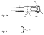
- two projections on the bar can be adapted such that the outer portions of the hose guiding member 8 is in contact with these when the hose guiding member 8 is moved along the beam 10.
- the projections which are further illustrated in fig 3 , may also be utilised when mounting the bar, e.g. by inserting a plate attached to a ground based platform between the two projections.
- Fig 4a, fig 4b and fig 4c illustrate the hose guiding member 8, the hose guiding member holder 9 and the hose in different views.
- the depth of the groove of the hose guiding member 8 is larger than the diameter of the hose. This has the effect that when the hose guiding member 8 and the hose guiding member holder 9 moves along the beam 10, the hose is not squeezed between the hose guiding member 8 and the beam 10.
- the hose guiding member 8 is further illustrated in fig 5a and fig 5b .
- the hose guiding member 8 can be provided with a number of holes on the inner portion, constituting the bottom of the groove, as well as on the outer portions, constituting the sides of the groove.
- the elastic band 13 which may be attached to said hose guiding member 8 or said hose guiding member holder 9 can be replaced with a rigid wire or the like. In this case, a retraction effect is achieved by a weight also attached to said wire.
- the length of the projections of the beam 10 and the depth of the groove can be larger than the diameter of the hose.
- the hose guiding member 8 passes the cross bar 12
- the hose will be squeezed between the cross bar 12 and the beam 10. This is a disadvantage since the hose cannot be pulled out as smooth and easy as in the embodiment where the depth of the groove is larger than the diameter of the hose. Further, a smaller hose guiding member will make it less easy to pull out the hose.
Landscapes
- Engineering & Computer Science (AREA)
- Mechanical Engineering (AREA)
- Loading And Unloading Of Fuel Tanks Or Ships (AREA)
Claims (13)
- Kraftstoffabgabeeinheit (1), wie zum Beispiel eine Benzinpumpe, Folgendes aufweisend:einen Schlauch, ein Schlauchführungselement (8), das eine Rotationsachse (16) und eine Hohlkehle, die zum Aufnehmen des Schlauchs angepasst ist, aufweist,Führungsmittel (10) mit einem Profil, das als ein U ausgebildet ist, das angepasst ist, um das Schlauchführungselement (8) zu führen, wobei das Führungsmittel (10) eine Hohlkehle aufweist, die angepasst ist, um das Schlauchführungselement (8) aufzunehmen,wobei das Schlauchführungselement (8) Folgendes aufweisteinen ersten und einen zweiten Außenabschnitt, die einen ersten Radius haben, undeinen Innenabschnitt, der einen zweiten Radius hat, wobei der Innenabschnitt zwischen dem ersten und dem zweiten Außenabschnitt platziert ist,wobei der erste und der zweite Außenabschnitt und der Innenabschnitt die Hohlkehle bilden,wobei der Unterschied zwischen dem ersten Radius und dem zweiten Radius größer ist als der Durchmesser des Schlauchs, so dass die Tiefe der Hohlkehle in dem Schlauchführungselement (8) größer ist als der Durchmesser des Schlauchs und der Schlauch nicht zwischen dem Schlauchführungselement und den Führungsmitteln (10) gequetscht wird.
- Kraftstoffabgabeeinheit (1) nach Anspruch 1, wobei das Schlauchführungselement (8) aus einem leitenden Kunststoff hergestellt ist.
- Kraftstoffabgabeeinheit (1) nach einem der vorhergehenden Ansprüche, wobei die Hohlkehle mit einer Anzahl von Löchern versehen ist.
- Kraftstoffabgabeeinheit (1) nach einem der vorhergehenden Ansprüche, wobei das Schlauchführungselement (8) ein Rad ist.
- Kraftstoffabgabeeinheit (1) nach einem der vorhergehenden Ansprüche, wobei der erste und der zweite Außenabschnitt des Schlauchführungselements (8) eingerichtet sind, um mit dem Führungsmittel (10) in Berührung zu sein.
- Kraftstoffabgabeeinheit (1) nach einem der vorhergehenden Ansprüche, wobei das Führungsmittel (10) einen U-förmigen Querschnitt hat, so dass das Schlauchführungselement (8) geführt wird, um um die Rotationsachse (16) des Schlauchführungselements (8) zu drehen.
- Kraftstoffabgabeeinheit (1) nach einem der vorhergehenden Ansprüche, wobei das Führungsmittel (10) Teil eines Gerüsts für ein Gehäuse (5) der Kraftstoffabgabeeinheit (1) ist.
- Kraftstoffabgabeeinheit (1) nach einem der vorhergehenden Ansprüche, ferner aufweisend
einen Schlauchführungselementhalter (9), der eingerichtet ist, um das Schlauchführungselement (8) zu halten. - Kraftstoffabgabeeinheit (1) nach Anspruch 8, die ferner mindestens ein elastisches Element (13) aufweist, das an dem Schlauchführungselementhalter (9) befestigt ist.
- Kraftstoffabgabeeinheit (1) nach einem der vorhergehenden Ansprüche, ferner aufweisend
mindestens ein elastisches Element (13), das an dem Schlauchführungselement (8) befestigt ist. - Kraftstoffabgabeeinheit (1) nach einem der Ansprüche 9 oder 10, wobei das mindestens eine elastische Element (13) ein beliebiges Element aus der Gruppe einer Feder und eines Gummibands ist.
- Kraftstoffabgabeeinheit (1) nach einem der vorhergehenden Ansprüche, ferner aufweisend
eine Stange (12) senkrecht zu und befestigt an dem Führungsmittel (10), die dadurch den Schlauchführungselementhalter (9) am Passieren entlang des Führungsmittels hindert. - Kraftstoffabgabeeinheit (1) nach Anspruch 12, wobei die Stange (12) einen U-förmigen Querschnitt hat.
Priority Applications (1)
| Application Number | Priority Date | Filing Date | Title |
|---|---|---|---|
| EP20080172407 EP2199250B1 (de) | 2008-12-19 | 2008-12-19 | Schlauchführrad |
Applications Claiming Priority (1)
| Application Number | Priority Date | Filing Date | Title |
|---|---|---|---|
| EP20080172407 EP2199250B1 (de) | 2008-12-19 | 2008-12-19 | Schlauchführrad |
Publications (2)
| Publication Number | Publication Date |
|---|---|
| EP2199250A1 EP2199250A1 (de) | 2010-06-23 |
| EP2199250B1 true EP2199250B1 (de) | 2013-06-12 |
Family
ID=40456957
Family Applications (1)
| Application Number | Title | Priority Date | Filing Date |
|---|---|---|---|
| EP20080172407 Not-in-force EP2199250B1 (de) | 2008-12-19 | 2008-12-19 | Schlauchführrad |
Country Status (1)
| Country | Link |
|---|---|
| EP (1) | EP2199250B1 (de) |
Families Citing this family (1)
| Publication number | Priority date | Publication date | Assignee | Title |
|---|---|---|---|---|
| SE544682C2 (en) * | 2020-10-23 | 2022-10-18 | Dover Fueling Solutions Uk Ltd | A device for handling a hose in a fuel dispensing unit |
Family Cites Families (7)
| Publication number | Priority date | Publication date | Assignee | Title |
|---|---|---|---|---|
| US2623732A (en) * | 1949-06-18 | 1952-12-30 | Kenneth F Morgan | Pulley winch |
| US4730652A (en) * | 1984-11-06 | 1988-03-15 | Proprietary Technology, Inc. | Automotive fuel filler system |
| US5018549A (en) * | 1986-08-05 | 1991-05-28 | Shell Internationale Research Maatschappij B.V. | Pump column |
| EP0369089B1 (de) * | 1988-11-15 | 1991-04-24 | Scheidt & Bachmann Gmbh | Vorrichtung zur Abgabe von Kraftstoffen an Kraftfahrzeuge |
| US5450874A (en) * | 1994-07-05 | 1995-09-19 | Hamula; Warren | Dental instrument hose retraction device |
| US6334457B1 (en) * | 1999-03-02 | 2002-01-01 | Dresser, Inc. | Collapsing hose management system and method for gasoline dispensing unit |
| EP2006245A1 (de) * | 2007-06-20 | 2008-12-24 | Dresser Wayne Aktiebolag | Vorrichtung und Verfahren zur Handhabung eines Schlauchs |
-
2008
- 2008-12-19 EP EP20080172407 patent/EP2199250B1/de not_active Not-in-force
Also Published As
| Publication number | Publication date |
|---|---|
| EP2199250A1 (de) | 2010-06-23 |
Similar Documents
| Publication | Publication Date | Title |
|---|---|---|
| CN107531477B (zh) | 用于安置至少一个软管的设备以及具有这种设备的燃料分配单元 | |
| EP2147892B1 (de) | Vorrichtung und Verfahren zur Handhabung eines Schlauchs und Brennstoffabgabeeinheit mit einer solchen Vorrichtung | |
| KR101505332B1 (ko) | 기계식 입체 주차장의 팔레트 및 이것을 구비한 기계식 입체 주차장 | |
| US20140034382A1 (en) | Electrical cable for the energy supply of vehicles | |
| US6334457B1 (en) | Collapsing hose management system and method for gasoline dispensing unit | |
| EP2006245A1 (de) | Vorrichtung und Verfahren zur Handhabung eines Schlauchs | |
| WO2011141138A3 (en) | Device for adjusting the length of infusion tubing | |
| US20150129703A1 (en) | Motorized hose reel with anti-rotation interlock | |
| EP2199250B1 (de) | Schlauchführrad | |
| GB2360506A (en) | Gasoline dispensing unit with improved hose handling | |
| EP2163511B1 (de) | Vorrichtung zur Handhabung eines Schlauchs und Brennstoffabgabeeinheit mit einer solchen Vorrichtung | |
| US20170036721A1 (en) | Bicycle rack | |
| US10308498B2 (en) | Methods and devices for handling a fuel dispenser hose | |
| EP2199251B1 (de) | Schlauchführung | |
| EP2163512B1 (de) | Zapfpistolenaufnahme für eine Zapfsäule | |
| EP3790835B1 (de) | Servounterstützte kraftstoffschlauch-handhabungseinrichtung | |
| EP1832549B1 (de) | Zapfsäule mit Schlauchrückführung | |
| WO2019215161A1 (en) | Fuel dispenser with angled nozzle boot | |
| EP3790836B1 (de) | Motorisierte vorrichtung zur handhabung eines oder mehrerer schläuche in einer kraftstoffzapfsäule | |
| AU2019264805B2 (en) | A motor-driven device for handling a plurality of hoses in a fuel dispensing unit | |
| EP2949619B1 (de) | Vorrichtung zur handhabung eines schlauchs und brennstoffabgabeeinheit mit solch einer vorrichtung | |
| EP1666407B1 (de) | Zapfsäule mit Ausschnitt im Seitenpaneel | |
| CN208531304U (zh) | 文件夹升降装置和具有其的集装箱 | |
| SE2050357A1 (en) | Intelligent hose handling |
Legal Events
| Date | Code | Title | Description |
|---|---|---|---|
| PUAI | Public reference made under article 153(3) epc to a published international application that has entered the european phase |
Free format text: ORIGINAL CODE: 0009012 |
|
| AK | Designated contracting states |
Kind code of ref document: A1 Designated state(s): AT BE BG CH CY CZ DE DK EE ES FI FR GB GR HR HU IE IS IT LI LT LU LV MC MT NL NO PL PT RO SE SI SK TR |
|
| AX | Request for extension of the european patent |
Extension state: AL BA MK RS |
|
| 17P | Request for examination filed |
Effective date: 20101222 |
|
| RIN1 | Information on inventor provided before grant (corrected) |
Inventor name: SASSNER, LINDA Inventor name: LARSSON, BENGT Inventor name: LARSSON, JOHN |
|
| AKX | Designation fees paid |
Designated state(s): AT BE BG CH CY CZ DE DK EE ES FI FR GB GR HR HU IE IS IT LI LT LU LV MC MT NL NO PL PT RO SE SI SK TR |
|
| GRAP | Despatch of communication of intention to grant a patent |
Free format text: ORIGINAL CODE: EPIDOSNIGR1 |
|
| RAP1 | Party data changed (applicant data changed or rights of an application transferred) |
Owner name: DRESSER WAYNE AB |
|
| GRAS | Grant fee paid |
Free format text: ORIGINAL CODE: EPIDOSNIGR3 |
|
| GRAP | Despatch of communication of intention to grant a patent |
Free format text: ORIGINAL CODE: EPIDOSNIGR1 |
|
| GRAA | (expected) grant |
Free format text: ORIGINAL CODE: 0009210 |
|
| AK | Designated contracting states |
Kind code of ref document: B1 Designated state(s): AT BE BG CH CY CZ DE DK EE ES FI FR GB GR HR HU IE IS IT LI LT LU LV MC MT NL NO PL PT RO SE SI SK TR |
|
| REG | Reference to a national code |
Ref country code: GB Ref legal event code: FG4D |
|
| REG | Reference to a national code |
Ref country code: CH Ref legal event code: EP |
|
| REG | Reference to a national code |
Ref country code: AT Ref legal event code: REF Ref document number: 616624 Country of ref document: AT Kind code of ref document: T Effective date: 20130615 |
|
| REG | Reference to a national code |
Ref country code: IE Ref legal event code: FG4D |
|
| REG | Reference to a national code |
Ref country code: DE Ref legal event code: R096 Ref document number: 602008025259 Country of ref document: DE Effective date: 20130808 |
|
| REG | Reference to a national code |
Ref country code: SE Ref legal event code: TRGR |
|
| REG | Reference to a national code |
Ref country code: ES Ref legal event code: FG2A Ref document number: 2426638 Country of ref document: ES Kind code of ref document: T3 Effective date: 20131024 |
|
| PG25 | Lapsed in a contracting state [announced via postgrant information from national office to epo] |
Ref country code: NO Free format text: LAPSE BECAUSE OF FAILURE TO SUBMIT A TRANSLATION OF THE DESCRIPTION OR TO PAY THE FEE WITHIN THE PRESCRIBED TIME-LIMIT Effective date: 20130912 Ref country code: LT Free format text: LAPSE BECAUSE OF FAILURE TO SUBMIT A TRANSLATION OF THE DESCRIPTION OR TO PAY THE FEE WITHIN THE PRESCRIBED TIME-LIMIT Effective date: 20130612 Ref country code: SI Free format text: LAPSE BECAUSE OF FAILURE TO SUBMIT A TRANSLATION OF THE DESCRIPTION OR TO PAY THE FEE WITHIN THE PRESCRIBED TIME-LIMIT Effective date: 20130612 Ref country code: GR Free format text: LAPSE BECAUSE OF FAILURE TO SUBMIT A TRANSLATION OF THE DESCRIPTION OR TO PAY THE FEE WITHIN THE PRESCRIBED TIME-LIMIT Effective date: 20130913 Ref country code: FI Free format text: LAPSE BECAUSE OF FAILURE TO SUBMIT A TRANSLATION OF THE DESCRIPTION OR TO PAY THE FEE WITHIN THE PRESCRIBED TIME-LIMIT Effective date: 20130612 |
|
| REG | Reference to a national code |
Ref country code: AT Ref legal event code: MK05 Ref document number: 616624 Country of ref document: AT Kind code of ref document: T Effective date: 20130612 |
|
| REG | Reference to a national code |
Ref country code: NL Ref legal event code: VDEP Effective date: 20130612 |
|
| REG | Reference to a national code |
Ref country code: LT Ref legal event code: MG4D |
|
| PG25 | Lapsed in a contracting state [announced via postgrant information from national office to epo] |
Ref country code: HR Free format text: LAPSE BECAUSE OF FAILURE TO SUBMIT A TRANSLATION OF THE DESCRIPTION OR TO PAY THE FEE WITHIN THE PRESCRIBED TIME-LIMIT Effective date: 20130612 Ref country code: BG Free format text: LAPSE BECAUSE OF FAILURE TO SUBMIT A TRANSLATION OF THE DESCRIPTION OR TO PAY THE FEE WITHIN THE PRESCRIBED TIME-LIMIT Effective date: 20130912 |
|
| PG25 | Lapsed in a contracting state [announced via postgrant information from national office to epo] |
Ref country code: LV Free format text: LAPSE BECAUSE OF FAILURE TO SUBMIT A TRANSLATION OF THE DESCRIPTION OR TO PAY THE FEE WITHIN THE PRESCRIBED TIME-LIMIT Effective date: 20130612 |
|
| PG25 | Lapsed in a contracting state [announced via postgrant information from national office to epo] |
Ref country code: IS Free format text: LAPSE BECAUSE OF FAILURE TO SUBMIT A TRANSLATION OF THE DESCRIPTION OR TO PAY THE FEE WITHIN THE PRESCRIBED TIME-LIMIT Effective date: 20131012 Ref country code: AT Free format text: LAPSE BECAUSE OF FAILURE TO SUBMIT A TRANSLATION OF THE DESCRIPTION OR TO PAY THE FEE WITHIN THE PRESCRIBED TIME-LIMIT Effective date: 20130612 Ref country code: EE Free format text: LAPSE BECAUSE OF FAILURE TO SUBMIT A TRANSLATION OF THE DESCRIPTION OR TO PAY THE FEE WITHIN THE PRESCRIBED TIME-LIMIT Effective date: 20130612 Ref country code: BE Free format text: LAPSE BECAUSE OF FAILURE TO SUBMIT A TRANSLATION OF THE DESCRIPTION OR TO PAY THE FEE WITHIN THE PRESCRIBED TIME-LIMIT Effective date: 20130612 Ref country code: SK Free format text: LAPSE BECAUSE OF FAILURE TO SUBMIT A TRANSLATION OF THE DESCRIPTION OR TO PAY THE FEE WITHIN THE PRESCRIBED TIME-LIMIT Effective date: 20130612 Ref country code: PT Free format text: LAPSE BECAUSE OF FAILURE TO SUBMIT A TRANSLATION OF THE DESCRIPTION OR TO PAY THE FEE WITHIN THE PRESCRIBED TIME-LIMIT Effective date: 20131014 |
|
| PG25 | Lapsed in a contracting state [announced via postgrant information from national office to epo] |
Ref country code: PL Free format text: LAPSE BECAUSE OF FAILURE TO SUBMIT A TRANSLATION OF THE DESCRIPTION OR TO PAY THE FEE WITHIN THE PRESCRIBED TIME-LIMIT Effective date: 20130612 Ref country code: NL Free format text: LAPSE BECAUSE OF FAILURE TO SUBMIT A TRANSLATION OF THE DESCRIPTION OR TO PAY THE FEE WITHIN THE PRESCRIBED TIME-LIMIT Effective date: 20130612 Ref country code: RO Free format text: LAPSE BECAUSE OF FAILURE TO SUBMIT A TRANSLATION OF THE DESCRIPTION OR TO PAY THE FEE WITHIN THE PRESCRIBED TIME-LIMIT Effective date: 20130612 |
|
| PLBE | No opposition filed within time limit |
Free format text: ORIGINAL CODE: 0009261 |
|
| STAA | Information on the status of an ep patent application or granted ep patent |
Free format text: STATUS: NO OPPOSITION FILED WITHIN TIME LIMIT |
|
| PG25 | Lapsed in a contracting state [announced via postgrant information from national office to epo] |
Ref country code: DK Free format text: LAPSE BECAUSE OF FAILURE TO SUBMIT A TRANSLATION OF THE DESCRIPTION OR TO PAY THE FEE WITHIN THE PRESCRIBED TIME-LIMIT Effective date: 20130612 |
|
| 26N | No opposition filed |
Effective date: 20140313 |
|
| REG | Reference to a national code |
Ref country code: DE Ref legal event code: R097 Ref document number: 602008025259 Country of ref document: DE Effective date: 20140313 |
|
| REG | Reference to a national code |
Ref country code: CH Ref legal event code: PL |
|
| PG25 | Lapsed in a contracting state [announced via postgrant information from national office to epo] |
Ref country code: LU Free format text: LAPSE BECAUSE OF FAILURE TO SUBMIT A TRANSLATION OF THE DESCRIPTION OR TO PAY THE FEE WITHIN THE PRESCRIBED TIME-LIMIT Effective date: 20131219 Ref country code: MC Free format text: LAPSE BECAUSE OF FAILURE TO SUBMIT A TRANSLATION OF THE DESCRIPTION OR TO PAY THE FEE WITHIN THE PRESCRIBED TIME-LIMIT Effective date: 20130612 |
|
| REG | Reference to a national code |
Ref country code: IE Ref legal event code: MM4A |
|
| PG25 | Lapsed in a contracting state [announced via postgrant information from national office to epo] |
Ref country code: IE Free format text: LAPSE BECAUSE OF NON-PAYMENT OF DUE FEES Effective date: 20131219 Ref country code: LI Free format text: LAPSE BECAUSE OF NON-PAYMENT OF DUE FEES Effective date: 20131231 Ref country code: CH Free format text: LAPSE BECAUSE OF NON-PAYMENT OF DUE FEES Effective date: 20131231 |
|
| PGFP | Annual fee paid to national office [announced via postgrant information from national office to epo] |
Ref country code: SE Payment date: 20141218 Year of fee payment: 7 Ref country code: CZ Payment date: 20141210 Year of fee payment: 7 Ref country code: ES Payment date: 20141215 Year of fee payment: 7 |
|
| PGFP | Annual fee paid to national office [announced via postgrant information from national office to epo] |
Ref country code: IT Payment date: 20141216 Year of fee payment: 7 |
|
| PGFP | Annual fee paid to national office [announced via postgrant information from national office to epo] |
Ref country code: FR Payment date: 20141212 Year of fee payment: 7 |
|
| PG25 | Lapsed in a contracting state [announced via postgrant information from national office to epo] |
Ref country code: CY Free format text: LAPSE BECAUSE OF FAILURE TO SUBMIT A TRANSLATION OF THE DESCRIPTION OR TO PAY THE FEE WITHIN THE PRESCRIBED TIME-LIMIT Effective date: 20130612 Ref country code: TR Free format text: LAPSE BECAUSE OF FAILURE TO SUBMIT A TRANSLATION OF THE DESCRIPTION OR TO PAY THE FEE WITHIN THE PRESCRIBED TIME-LIMIT Effective date: 20130612 |
|
| PG25 | Lapsed in a contracting state [announced via postgrant information from national office to epo] |
Ref country code: HU Free format text: LAPSE BECAUSE OF FAILURE TO SUBMIT A TRANSLATION OF THE DESCRIPTION OR TO PAY THE FEE WITHIN THE PRESCRIBED TIME-LIMIT; INVALID AB INITIO Effective date: 20081219 |
|
| PG25 | Lapsed in a contracting state [announced via postgrant information from national office to epo] |
Ref country code: MT Free format text: LAPSE BECAUSE OF FAILURE TO SUBMIT A TRANSLATION OF THE DESCRIPTION OR TO PAY THE FEE WITHIN THE PRESCRIBED TIME-LIMIT Effective date: 20130612 |
|
| PG25 | Lapsed in a contracting state [announced via postgrant information from national office to epo] |
Ref country code: CZ Free format text: LAPSE BECAUSE OF NON-PAYMENT OF DUE FEES Effective date: 20151219 |
|
| REG | Reference to a national code |
Ref country code: SE Ref legal event code: EUG |
|
| PG25 | Lapsed in a contracting state [announced via postgrant information from national office to epo] |
Ref country code: SE Free format text: LAPSE BECAUSE OF NON-PAYMENT OF DUE FEES Effective date: 20151220 |
|
| REG | Reference to a national code |
Ref country code: FR Ref legal event code: ST Effective date: 20160831 |
|
| PG25 | Lapsed in a contracting state [announced via postgrant information from national office to epo] |
Ref country code: FR Free format text: LAPSE BECAUSE OF NON-PAYMENT OF DUE FEES Effective date: 20151231 |
|
| PG25 | Lapsed in a contracting state [announced via postgrant information from national office to epo] |
Ref country code: IT Free format text: LAPSE BECAUSE OF NON-PAYMENT OF DUE FEES Effective date: 20151219 |
|
| PG25 | Lapsed in a contracting state [announced via postgrant information from national office to epo] |
Ref country code: ES Free format text: LAPSE BECAUSE OF NON-PAYMENT OF DUE FEES Effective date: 20151220 |
|
| REG | Reference to a national code |
Ref country code: DE Ref legal event code: R081 Ref document number: 602008025259 Country of ref document: DE Owner name: DOVER FUELING SOLUTIONS UK LTD., GB Free format text: FORMER OWNER: DRESSER WAYNE AB, MALMOE, SE |
|
| REG | Reference to a national code |
Ref country code: GB Ref legal event code: 732E Free format text: REGISTERED BETWEEN 20220901 AND 20220907 |
|
| P01 | Opt-out of the competence of the unified patent court (upc) registered |
Effective date: 20230529 |
|
| PGFP | Annual fee paid to national office [announced via postgrant information from national office to epo] |
Ref country code: GB Payment date: 20231219 Year of fee payment: 16 |
|
| PGFP | Annual fee paid to national office [announced via postgrant information from national office to epo] |
Ref country code: DE Payment date: 20231227 Year of fee payment: 16 |
|
| REG | Reference to a national code |
Ref country code: DE Ref legal event code: R119 Ref document number: 602008025259 Country of ref document: DE |
|
| GBPC | Gb: european patent ceased through non-payment of renewal fee |
Effective date: 20241219 |
|
| PG25 | Lapsed in a contracting state [announced via postgrant information from national office to epo] |
Ref country code: DE Free format text: LAPSE BECAUSE OF NON-PAYMENT OF DUE FEES Effective date: 20250701 |
|
| PG25 | Lapsed in a contracting state [announced via postgrant information from national office to epo] |
Ref country code: GB Free format text: LAPSE BECAUSE OF NON-PAYMENT OF DUE FEES Effective date: 20241219 |