EP2199416A1 - Abschreckverfahren und vorrichtung für ringförmigen gegenstand - Google Patents
Abschreckverfahren und vorrichtung für ringförmigen gegenstand Download PDFInfo
- Publication number
- EP2199416A1 EP2199416A1 EP08834332A EP08834332A EP2199416A1 EP 2199416 A1 EP2199416 A1 EP 2199416A1 EP 08834332 A EP08834332 A EP 08834332A EP 08834332 A EP08834332 A EP 08834332A EP 2199416 A1 EP2199416 A1 EP 2199416A1
- Authority
- EP
- European Patent Office
- Prior art keywords
- shaped article
- ring shaped
- quenching
- heating
- temperature
- Prior art date
- Legal status (The legal status is an assumption and is not a legal conclusion. Google has not performed a legal analysis and makes no representation as to the accuracy of the status listed.)
- Granted
Links
Images



Classifications
-
- C—CHEMISTRY; METALLURGY
- C21—METALLURGY OF IRON
- C21D—MODIFYING THE PHYSICAL STRUCTURE OF FERROUS METALS; GENERAL DEVICES FOR HEAT TREATMENT OF FERROUS OR NON-FERROUS METALS OR ALLOYS; MAKING METAL MALLEABLE, e.g. BY DECARBURISATION OR TEMPERING
- C21D1/00—General methods or devices for heat treatment, e.g. annealing, hardening, quenching or tempering
- C21D1/62—Quenching devices
- C21D1/63—Quenching devices for bath quenching
-
- B—PERFORMING OPERATIONS; TRANSPORTING
- B21—MECHANICAL METAL-WORKING WITHOUT ESSENTIALLY REMOVING MATERIAL; PUNCHING METAL
- B21B—ROLLING OF METAL
- B21B1/00—Metal-rolling methods or mills for making semi-finished products of solid or profiled cross-section; Sequence of operations in milling trains; Layout of rolling-mill plant, e.g. grouping of stands; Succession of passes or of sectional pass alternations
-
- B—PERFORMING OPERATIONS; TRANSPORTING
- B21—MECHANICAL METAL-WORKING WITHOUT ESSENTIALLY REMOVING MATERIAL; PUNCHING METAL
- B21B—ROLLING OF METAL
- B21B35/00—Drives for metal-rolling mills, e.g. hydraulic drives
-
- C—CHEMISTRY; METALLURGY
- C21—METALLURGY OF IRON
- C21D—MODIFYING THE PHYSICAL STRUCTURE OF FERROUS METALS; GENERAL DEVICES FOR HEAT TREATMENT OF FERROUS OR NON-FERROUS METALS OR ALLOYS; MAKING METAL MALLEABLE, e.g. BY DECARBURISATION OR TEMPERING
- C21D1/00—General methods or devices for heat treatment, e.g. annealing, hardening, quenching or tempering
- C21D1/34—Methods of heating
- C21D1/42—Induction heating
-
- C—CHEMISTRY; METALLURGY
- C21—METALLURGY OF IRON
- C21D—MODIFYING THE PHYSICAL STRUCTURE OF FERROUS METALS; GENERAL DEVICES FOR HEAT TREATMENT OF FERROUS OR NON-FERROUS METALS OR ALLOYS; MAKING METAL MALLEABLE, e.g. BY DECARBURISATION OR TEMPERING
- C21D1/00—General methods or devices for heat treatment, e.g. annealing, hardening, quenching or tempering
- C21D1/62—Quenching devices
- C21D1/667—Quenching devices for spray quenching
-
- C—CHEMISTRY; METALLURGY
- C21—METALLURGY OF IRON
- C21D—MODIFYING THE PHYSICAL STRUCTURE OF FERROUS METALS; GENERAL DEVICES FOR HEAT TREATMENT OF FERROUS OR NON-FERROUS METALS OR ALLOYS; MAKING METAL MALLEABLE, e.g. BY DECARBURISATION OR TEMPERING
- C21D7/00—Modifying the physical properties of iron or steel by deformation
- C21D7/02—Modifying the physical properties of iron or steel by deformation by cold working
-
- C—CHEMISTRY; METALLURGY
- C21—METALLURGY OF IRON
- C21D—MODIFYING THE PHYSICAL STRUCTURE OF FERROUS METALS; GENERAL DEVICES FOR HEAT TREATMENT OF FERROUS OR NON-FERROUS METALS OR ALLOYS; MAKING METAL MALLEABLE, e.g. BY DECARBURISATION OR TEMPERING
- C21D7/00—Modifying the physical properties of iron or steel by deformation
- C21D7/13—Modifying the physical properties of iron or steel by deformation by hot working
-
- C—CHEMISTRY; METALLURGY
- C21—METALLURGY OF IRON
- C21D—MODIFYING THE PHYSICAL STRUCTURE OF FERROUS METALS; GENERAL DEVICES FOR HEAT TREATMENT OF FERROUS OR NON-FERROUS METALS OR ALLOYS; MAKING METAL MALLEABLE, e.g. BY DECARBURISATION OR TEMPERING
- C21D9/00—Heat treatment, e.g. annealing, hardening, quenching or tempering, adapted for particular articles; Furnaces therefor
- C21D9/08—Heat treatment, e.g. annealing, hardening, quenching or tempering, adapted for particular articles; Furnaces therefor for tubular bodies or pipes
- C21D9/085—Cooling or quenching
-
- C—CHEMISTRY; METALLURGY
- C21—METALLURGY OF IRON
- C21D—MODIFYING THE PHYSICAL STRUCTURE OF FERROUS METALS; GENERAL DEVICES FOR HEAT TREATMENT OF FERROUS OR NON-FERROUS METALS OR ALLOYS; MAKING METAL MALLEABLE, e.g. BY DECARBURISATION OR TEMPERING
- C21D9/00—Heat treatment, e.g. annealing, hardening, quenching or tempering, adapted for particular articles; Furnaces therefor
- C21D9/40—Heat treatment, e.g. annealing, hardening, quenching or tempering, adapted for particular articles; Furnaces therefor for rings; for bearing races
-
- F—MECHANICAL ENGINEERING; LIGHTING; HEATING; WEAPONS; BLASTING
- F16—ENGINEERING ELEMENTS AND UNITS; GENERAL MEASURES FOR PRODUCING AND MAINTAINING EFFECTIVE FUNCTIONING OF MACHINES OR INSTALLATIONS; THERMAL INSULATION IN GENERAL
- F16C—SHAFTS; FLEXIBLE SHAFTS; ELEMENTS OR CRANKSHAFT MECHANISMS; ROTARY BODIES OTHER THAN GEARING ELEMENTS; BEARINGS
- F16C33/00—Parts of bearings; Special methods for making bearings or parts thereof
- F16C33/30—Parts of ball or roller bearings
- F16C33/58—Raceways; Race rings
- F16C33/64—Special methods of manufacture
-
- C—CHEMISTRY; METALLURGY
- C21—METALLURGY OF IRON
- C21D—MODIFYING THE PHYSICAL STRUCTURE OF FERROUS METALS; GENERAL DEVICES FOR HEAT TREATMENT OF FERROUS OR NON-FERROUS METALS OR ALLOYS; MAKING METAL MALLEABLE, e.g. BY DECARBURISATION OR TEMPERING
- C21D7/00—Modifying the physical properties of iron or steel by deformation
- C21D7/02—Modifying the physical properties of iron or steel by deformation by cold working
- C21D7/10—Modifying the physical properties of iron or steel by deformation by cold working of the whole cross-section, e.g. of concrete reinforcing bars
-
- Y—GENERAL TAGGING OF NEW TECHNOLOGICAL DEVELOPMENTS; GENERAL TAGGING OF CROSS-SECTIONAL TECHNOLOGIES SPANNING OVER SEVERAL SECTIONS OF THE IPC; TECHNICAL SUBJECTS COVERED BY FORMER USPC CROSS-REFERENCE ART COLLECTIONS [XRACs] AND DIGESTS
- Y02—TECHNOLOGIES OR APPLICATIONS FOR MITIGATION OR ADAPTATION AGAINST CLIMATE CHANGE
- Y02P—CLIMATE CHANGE MITIGATION TECHNOLOGIES IN THE PRODUCTION OR PROCESSING OF GOODS
- Y02P10/00—Technologies related to metal processing
- Y02P10/25—Process efficiency
Definitions
- the present invention relates to a method of quenching a ring shaped article such as, for example, a bearing raceway ring or the like, which is performed while correction of a thermal deformation of the ring shaped article is carried out, and an apparatus accomplishing such quenching.
- the ring shaped article W is cooled down to a temperature near to a martensitic transformation point (martensitic transformation temperature: 230°C) without being restrained in any arresting die; when it is cooled down to such temperature, the ring shaped article W is placed inside the arresting die 40 and is then cooled down to a predetermined temperature (about 110°C); after the ring shaped article W has been cooled down to such temperature, the ring shaped article W is removed from the arresting die 40; and thereafter the ring shaped article W is allowed to cool naturally down to room temperature.
- a quenching temperature about 850°C
- the method has been suggested, in which using the arresting die of an axially elongated and vertically extending cylindrical configuration, a ring shaped article then at a cooling step of the quenching process is forcible inserted into the vertically cylindrical arresting die sequentially from above so that the ring shaped article within the arresting die can be pushed sequentially outwardly from below.
- An object of the present invention is to provide a method of, and an apparatus for, quenching a ring shaped article, in which thermal deformation of the ring shaped article, which occurs as a result of the quenching treatment, can be corrected during the quenching treatment of such ring shaped article; such correction of the thermal deformation can be accomplished without substantially requiring a cost and a labor and can be applied to ring shaped articles of varying sizes; the ring shaped article can be efficiently heated to the quenching temperature; the required heating time is short; and the required equipment is compact.
- a method of quenching a ring shaped article in accordance with the present invention includes a heating step of heating the ring shaped article to a quenching temperature; a primary cooling step of cooling the ring shaped article, which has been heated to the quenching temperature, down to a deformation correction initiating temperature, which is higher than a martensitic transformation point; and a secondary cooling step of cooling the ring shaped article, which has been cooled down to the deformation correction initiating temperature, down to a temperature lower than the martensitic transformation point by, while a pair of receiving rolls are held in contact with an outer peripheral surface of such ring shaped article for rotation about an axis of rotation, which is parallel to a center of the ring shaped article, pressing a press roll, rotatable about an axis of rotation parallel to the center of the ring shaped article, against the outer peripheral surface of the ring shaped article from one side of the ring shaped article opposite to a point intermediate between the receiving rolls.
- the press roll then rotating is urged against the outer peripheral surface of the ring shaped articles from the opposite side of the receiving rolls, the ring shaped article is cooled.
- the deformation occurring in the ring shaped article can be corrected with the circularity increased consequently.
- This deformation correction is performed with no use of any arresting die and, therefore, no cost is incurred in utilizing the arresting die and neither a work to mount the ring shaped article on the arresting die nor a work to remove the ring shaped article from the arresting die is required. Since the deformation correction is performed during the secondary cooling step, no extra step for the deformation correction need not be employed.
- the heating step is carried out by induction heating.
- the heating step includes a preheating step of heating by induction heating the ring shaped article to a predetermined preheating temperature near to the quenching temperature and a soaking step of heating the ring shaped article, which has been heated to the preheating temperature, to the quenching temperature within a continuous heating furnace.
- the ring shaped article since the ring shaped article is heated to the quenching temperature with the use of the preheating step for heating by induction heating and the soaking step for heating within a continuous heating furnace, the ring shaped article can be heated deep by induction heating in a matter of minutes with a good energy efficiency and, also, due to the use of the continuous heating furnace, the ring shaped article in its entirety can be soaked.
- the continuous heating furnace is used only for the purpose of heating the ring shaped article, which has been preheated to a temperature near to the quenching temperature, to the quenching temperature, and, therefore, the heating time can be reduced considerably in contrast to that required to heat from room temperature and the path of transport, through which the ring shaped article is transported within the furnace, may be short and, therefore, resulting in reduction of the size of the equipment.
- the length of time during which the press roll is urged against the outer peripheral surface of the ring shaped article is preferably within the range of 40 to 90 seconds.
- the temperature of the ring shaped article at the time a deformation correction is initiated with the press roll urged against the outer peripheral surface of the ring shaped article is preferably 20°C to 50°C higher than the martensitic transformation point.
- the length of time during which the deformation correction is carried out with the press roll urged against the outer peripheral surface of the ring shaped article is preferred within the range of 40 to 90 seconds. Also, in order to complete the deformation correction during the cooling step for quenching while the above described length of time during which the deformation correction is carried out is secured, it has been found preferred that urging of the press roll has to be initiated from the temperature that is 20°C to 50°C higher than the martensitic transformation point.
- An apparatus for quenching a ring shaped article includes a heating station for heating the ring shaped article to a quenching temperature; a primary cooling station for cooling the ring shaped article, which has been heated to the quenching temperature by the heating station, down to a deformation correction initiating temperature, which is higher than a martensitic transformation point; and a secondary cooling station for cooling the ring shaped article, which has been cooled down to the deformation correction initiating temperature by the primary cooling station, down to a temperature lower than the martensitic transformation point by, while a pair of receiving rolls are held in contact with an outer peripheral surface of such ring shaped article for rolling motion about an axis of rotation, which is parallel to a center of the ring shaped article, pressing a press roll, rotatable about an axis of rotation parallel to the center of the ring shaped article, against the outer peripheral surface of the ring shaped article from one side of the ring shaped article opposite to a point intermediate between the receiving rolls
- the ring shaped article quenching apparatus the ring shaped article is cooled at the secondary cooling station in a condition in which while the pair of the receiving rolls are rotatably held in contact with the outer peripheral surface of the ring shaped article, the press roll then rotating is urged against the outer peripheral surface of the ring shaped article from the opposite side.
- the deformation occurring in the ring shaped article can be corrected with the circularity increased consequently.
- the apparatus can be suited to the ring shaped articles of varying sizes.
- This deformation correction is performed with no use of any arresting die and, therefore, no cost is incurred in utilizing the arresting die and neither a work to mount the ring shaped article on the arresting die nor a work to remove the ring shaped article from the arresting die is required. Since the deformation correction is performed during the secondary cooling step, no extra step for the deformation correction need not be employed.
- the heating station is operable to perform an induction heating.
- the ring shaped article since the ring shaped article is heated to the quenching temperature with the use of the preheating station, at which heating by induction heating takes place, and the soaking station, at which heating takes place within a continuous heating furnace, the ring shaped article can be heated deep by induction heating in a matter of minutes with a good energy efficiency and, also, due to the use of the continuous heating furnace, the ring shaped article in its entirety can be soaked.
- the continuous heating furnace is used only for the purpose of heating the ring shaped article, which has been preheated to a temperature near to the quenching temperature, to the quenching temperature, and, therefore, the heating time can be reduced considerably in contrast to that required to heat from room temperature and the path of transport, through which the ring shaped article is transported within the furnace, may be short and, therefore, resulting in reduction of the size of the equipment.
- the primary cooling station 32 is for primarily cooling the ring shaped article W, which has been heated to the quenching temperature, down to a temperature (for example, 290°C), which is higher than the martensitic transformation point, by immersing such ring shaped article W within a quenching oil contained in a primary cooling bath 32a (a primary cooling step S2).
- the secondary cooling station 33 is for secondarily cooling the ring shaped article W, which has been primarily cooled, down to a predetermined temperature (for example, 110°C) by immersing a quenching oil, contained in an oil bath 20, while a deformation correction is performed by means of a deformation correcting device 1 (a secondary cooling step S3).
- the cleansing station 34 is for cleansing the ring shaped article W, which has been secondarily cooled, and then transferring it to the subsequent processing step.
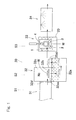
- a portion of the top surface of the support table 2 between the pair of the receiving rolls 3 and the press roll 4 is designed as a ring shaped article support area 5 and a region thereof ranging from one to the other of opposite ends in a direction (Y-axis direction) of arrangement of the receiving rolls 3 is so formed as to lie at a level higher than that of the other portion thereof.
- This ring shaped article support area 5 is formed with a cutout 5a for the purpose of avoiding an interference thereof with the press roll 4 and the press roll support member 11 when the press roll 4 is advanced as will be described later.
- a loading and discharging mechanism (not shown) for loading the ring shaped article W onto the ring shaped article support area 5 from a direction shown by the arrow A and discharging the ring shaped article W from the ring shaped article support area 5 towards a direction shown by the arrow B.
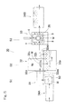
- the deformation correction accomplished by the deformation correcting device 1 at the secondary cooling station 33 shown in Fig. 1 , will now be described with particular reference to Figs. 2A and 2B .
- the deformation correcting device 1 is held standby at a retracted position P1 with the press roll 4 having been retracted relative to the receiving rolls 3 as shown by the chain line in Fig. 2A .
- the support table 2 is held in a horizontal condition.
- the ring shaped article W shown by the chain line and emerging outwardly from the primarily cooling bath 32a shown in Fig.
- the press roll 4 is driven to rotate the press roll 4 in the predetermined direction. While the ring shaped article W is restrained under a predetermined load by the pair of the receiving rolls 3 and the press roll 4 from the opposite sides, the ring shaped article W is rotated between the rolls 3 and 4 so that a deformation can be corrected to allow the ring shaped article W to have an increased circularity.
- the tilting unit 23 of the deformation correcting time cooling mechanism 21 is driven to tilt the support table 2 with the ring shaped article support area 5 lowered consequently. Accordingly, the ring shaped article W is immersed into the quenching oil contained in the oil bath 20 and is therefore secondarily cooled. Since loading of the ring shaped article W onto the ring shaped article support area 5, advance of the press roll 4, rotation of the press roll 4 and tilting of the support table 2 take place continuously, the primary cooling and the secondary cooling are performed with no substantial time spent therebetween. For this reason, quenching takes place favorably.
- the ring shaped article W so released is, by the action of the loading and discharging mechanism (not shown), discharged in a direction, shown by B in Fig. 2A . from the ring shaped article support area 5 of the support table 2 to the outside of the support table 2.
- the deformation correcting device 1 of the construction described above designed for the ring shaped article is such that since the press roll 4 can be selectively movable between the advanced and retracted positions, the distance between the pair of the receiving rolls 3 and the press roll 4 can be changed as desired. For this reason, it can be applied to ring shaped articles W of any varying diameters.
- the spacing between the receiving rolls 3 may be changed by the receiving roll interval adjusting mechanism 6 to suit to the size of the ring shaped article W.
- the deformation correction of the ring shaped article W by the deformation correcting device 1 require no allowance for a die, since no arresting die is utilized, and, also, no work is required to mount the ring shaped article W onto the die nor remove it from the die.
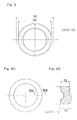
- the amount of change in outer diameter ⁇ D represents the difference between the outer diameter D1 before the deformation correction and the outer diameter D2 after the deformation correction ( Fig. 3 ).
- the amount of change in wall thickness ⁇ T represents the difference between the wall thickness T1 before the deformation correction and the wall thickness T2 after the deformation correction ( Figs. 4A and 4B ).
- the average value x, the standard deviation value ⁇ and the maximum value Max were determined. Results of those tests are tabulated in Table 1 below. Table 1 230°C 250°C 280°C Load X ⁇ Max x ⁇ Max x ⁇ Max 150 kgf Amt. of Outer Dia.
- the ring shaped article W which has been heated to the quenching temperature, is immersed in the quenching oil contained in the primary cooling bath 32a so that the ring shaped article W can be primarily cooled down to a temperature (for example, 290°C) that is higher than the martensitic transformation point (a primary cooling step S2).
- a temperature for example, 290°C
- the ring shaped article W which has been primarily cooled, is immersed into the quenching oil within the oil bath 20 while deformation thereof is corrected by the deformation correcting device 1, so that the ring shaped article W can be secondarily cooled down to a predetermined temperature (for example, 110°C) (a secondary cooling step S3).
- a predetermined temperature for example, 110°C
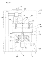
- This induction heating device 50 includes a rotary table 51 for turning a ring shaped article W, placed on such rotary table 51, about a ring center 01, a heating coil 52 and an alternating current power source 53 for supplying an electric current to the heating coil 52.
- the alternating current power source 53 is rendered to be, for example, a high frequency power source.
- a heating chamber 37, in which the induction heating device 50 is installed, is of an atmosphere filled with a nitrogen gas N 2 .
- the pre-cleansing station 34A swarfs and oil content, which adhere to the ring shaped article W during a turning process, are cleansed off.
- the ring shaped article W which has been pre-cleansed at the pre-cleansing station 34A, is heated by induction heating to a predetermined preheating temperature, which is near to the quenching temperature, by an induction heating device 50 (a heating step S1A).
- the ring shaped article W which has been heated to the preheating temperature, is heated to a predetermined quenching temperature (for example, 850°C) within the continuous heating furnace 31a (a soaking step S1B).
- the ring shaped article W which has been heated to the quenching temperature, is immersed in the quenching oil contained in the primary cooling bath 32a so that the ring shaped article W can be primarily cooled down to a temperature (for example, 290°C) that is higher than the martensitic transformation point (a primary cooling step S2).
- a primary cooling step S2 the ring shaped article W, which has been primarily cooled, is immersed into the quenching oil within the oil bath 20 while deformation thereof is corrected by the deformation correcting device 1, so that the ring shaped article W can be secondarily cooled down to a predetermined temperature (for example, 110°C) (a secondary cooling step S3).
- the post-cleansing station 34B the ring shaped article W, which has been secondarily cooled, is transferred to the subsequent processing step.
- the induction heating device 50 employed at the preheating station 31A used in the practice of the third preferred embodiment is of a structure identical with the induction heating device 50 employed at the heating station 31 used in the practice of the previously described second preferred embodiment and, therefore, the details thereof are not reiterated for the sake of brevity, but there is such a difference that in contrast to the use of the induction heating device 50 at the preheating station 31A according to the third embodiment for the purpose of heating by induction heating of the ring shaped article to the predetermined preheating temperature near to the quenching temperature, the heating station 31 according to the previously described second embodiment makes use of the induction heating device 50 for the purpose of heating to the quenching temperature.
- the structure and the description of the heating coil 52 shown in Figs. 7A and 7B and Figs. 8A and 8B are also equally applicable to the third preferred embodiment of the present invention and, therefore, the details thereof are not reiterated for the sake of brevity.
- the continuous heating furnace 31a at the soaking station 31B is a furnace for heating the ring shaped articles W while the latter are transported successively in a row by a transport unit 31b such as, for example, a conveyor within the interior of such furnace that is kept under a high temperature atmosphere.
- a transport unit 31b such as, for example, a conveyor within the interior of such furnace that is kept under a high temperature atmosphere.
- the quenching apparatus 30 of the third embodiment of the present invention since heating is effected to the quenching temperature through the preheating station 31A, at which the heating takes place by means of induction heating, and also through the soaking station 31B, at which the heating takes place by means of the continuous heating furnace 31a.
- the ring shaped article W can be heated deep by induction heating in a matter of minutes with a good energy efficiency and, also, due to the use of the continuous heating furnace 31a, the ring shaped article W in its entirety can be soaked.
- the continuous heating furnace 31a Since although the use is made of the continuous heating furnace 31a, the continuous heating furnace 31a is used only for the purpose of heating the ring shaped article W, which has been preheated to a temperature near to the quenching temperature, to the quenching temperature, the heating time can be reduced considerably in contrast to that required to heat from room temperature. Also, the path of transport, through which the ring shaped article W is transported within the furnace, may be short and, therefore, the equipment can be reduced in size.
- the deformation correcting device 1 according to any one of the foregoing embodiments of the present invention can be embodied in the following modes.
- the ring shaped article deformation correcting device as defined in Mode 1 above, further comprising a roll interval adjusting mechanism for adjusting the interval between the receiving rolls.
- the ring shaped article deformation correcting device as defined in Mode 1 above, in which the length of time required to perform a deformation correction with the press roll urged against the outer peripheral surface of the ring shaped article is within the range of 40 to 90 seconds.
- the ring shaped article deformation correcting device as defined in Mode 1 above, in which the temperature of the ring shaped article at the time a deformation correction is initiated with the press roll urged against the outer peripheral surface of the ring shaped article is 20°C to 50°C higher than the martensitic transformation point.
- the deformation correcting time cooling mechanism comprises a support unit for tiltably supporting the support table such that a ring shaped article support area of the support table, where the ring shaped article is placed, may be lowered, and a tilting unit for tilting the support table supported by the support unit, so that when the support table is tilted by the tilting unit, the ring shaped article can be immersed into the quenching oil within the oil bath.
Landscapes
- Chemical & Material Sciences (AREA)
- Engineering & Computer Science (AREA)
- Mechanical Engineering (AREA)
- Crystallography & Structural Chemistry (AREA)
- Materials Engineering (AREA)
- Metallurgy (AREA)
- Organic Chemistry (AREA)
- Physics & Mathematics (AREA)
- Thermal Sciences (AREA)
- General Engineering & Computer Science (AREA)
- Manufacturing & Machinery (AREA)
- Heat Treatment Of Articles (AREA)
Applications Claiming Priority (5)
| Application Number | Priority Date | Filing Date | Title |
|---|---|---|---|
| JP2007253290A JP5495483B2 (ja) | 2007-09-28 | 2007-09-28 | リング状品の焼入れ方法および装置 |
| JP2007253289A JP5500769B2 (ja) | 2007-09-28 | 2007-09-28 | リング状品の変形矯正装置 |
| JP2007253288A JP5495482B2 (ja) | 2007-09-28 | 2007-09-28 | リング状品の焼入れ方法および装置 |
| JP2007265389A JP5495485B2 (ja) | 2007-10-11 | 2007-10-11 | リング状品の焼入れ方法および装置 |
| PCT/JP2008/002633 WO2009041025A1 (ja) | 2007-09-28 | 2008-09-24 | リング状品の焼入れ方法および装置 |
Publications (3)
| Publication Number | Publication Date |
|---|---|
| EP2199416A1 true EP2199416A1 (de) | 2010-06-23 |
| EP2199416A4 EP2199416A4 (de) | 2013-08-14 |
| EP2199416B1 EP2199416B1 (de) | 2014-10-22 |
Family
ID=40510930
Family Applications (1)
| Application Number | Title | Priority Date | Filing Date |
|---|---|---|---|
| EP08834332.2A Active EP2199416B1 (de) | 2007-09-28 | 2008-09-24 | Abschreckverfahren und vorrichtung für ringförmigen gegenstand |
Country Status (4)
| Country | Link |
|---|---|
| US (3) | US8974613B2 (de) |
| EP (1) | EP2199416B1 (de) |
| CN (1) | CN101809174B (de) |
| WO (1) | WO2009041025A1 (de) |
Cited By (1)
| Publication number | Priority date | Publication date | Assignee | Title |
|---|---|---|---|---|
| NL2020091A (en) * | 2016-12-15 | 2018-06-19 | Skf Ab | Induction heating device |
Families Citing this family (24)
| Publication number | Priority date | Publication date | Assignee | Title |
|---|---|---|---|---|
| WO2009041025A1 (ja) * | 2007-09-28 | 2009-04-02 | Ntn Corporation | リング状品の焼入れ方法および装置 |
| JP5733555B2 (ja) * | 2010-08-27 | 2015-06-10 | 高周波熱錬株式会社 | 熱処理装置、環状部材及び熱処理方法 |
| JP5998438B2 (ja) * | 2011-07-25 | 2016-09-28 | 日本精工株式会社 | ワークの拘束焼入れ方法および拘束焼入れ装置 |
| CN103014246A (zh) * | 2011-09-28 | 2013-04-03 | 昆山鑫昌泰模具科技有限公司 | 金属热处理变形冷却校正同步法 |
| KR101507001B1 (ko) | 2011-12-30 | 2015-03-31 | 제일모직 주식회사 | 유기광전자소자용 화합물, 이를 포함하는 유기발광소자 및 상기 유기발광소자를 포함하는 표시장치 |
| CN102828008B (zh) * | 2012-09-04 | 2014-08-27 | 镇江市天祥精密机电有限公司 | 无心淬火机床 |
| CN103388058A (zh) * | 2013-08-16 | 2013-11-13 | 天津天模热处理有限公司 | 列车球型环铰接连接器感应淬火方法 |
| CN103725837A (zh) * | 2014-01-23 | 2014-04-16 | 唐山亚捷机械有限公司 | 油中自由冷却、机床上马氏体转变的压模淬火工艺及设备 |
| US10190185B2 (en) * | 2015-08-24 | 2019-01-29 | Jtekt Corporation | Hardening method of annular workpiece |
| GB2548416B (en) * | 2016-03-15 | 2019-06-12 | Arconic Inc | Improved methods for quenching metal tubes |
| RU2653520C1 (ru) * | 2017-03-28 | 2018-05-10 | федеральное государственное бюджетное образовательное учреждение высшего образования "Тольяттинский государственный университет" | Устройство для термосиловой правки валов |
| JP2019157163A (ja) * | 2018-03-08 | 2019-09-19 | Ntn株式会社 | ワークの熱処理方法及び熱処理装置 |
| CN108842049B (zh) * | 2018-08-11 | 2020-03-27 | 江阴市一鸣管业有限公司 | 一种用于内高压成形高塑性钢管的设备及方法 |
| CN109396807A (zh) * | 2018-12-14 | 2019-03-01 | 山西天海泵业有限公司 | 一种电机平衡环高效热装装置及热装方法 |
| CN109971939B (zh) * | 2019-03-29 | 2025-01-03 | 马鞍山华东回转支承有限公司 | 一种回转支承齿圈圆度的检测校正装置 |
| CN112719204B (zh) * | 2020-12-10 | 2024-02-23 | 合肥市远大轴承锻造有限公司 | 一种轴承套圈锻后冷却装置 |
| CN114799782A (zh) * | 2022-04-12 | 2022-07-29 | 乐清市芙蓉工具一厂 | 一种用于钻头的加工设备 |
| CN115418456B (zh) * | 2022-09-21 | 2023-10-13 | 江苏天工精密工具有限公司 | 一种高速钢高效淬火装置 |
| CN115786647B (zh) * | 2022-12-19 | 2025-05-09 | 江苏龙城精锻集团有限公司 | 一种同类导磁体感应器调整热处理变形量的制造方法 |
| CN118243047B (zh) * | 2024-03-27 | 2026-02-17 | 中国铁建重工集团股份有限公司 | 环件感应淬火变形量的计算方法 |
| JP2025165627A (ja) * | 2024-04-23 | 2025-11-05 | Ntn株式会社 | 焼入れ方法 |
| CN118497477B (zh) * | 2024-06-18 | 2024-10-25 | 诺通(常州)液压科技有限公司 | 一种液压管接头淬火装置 |
| CN118581314B (zh) * | 2024-08-05 | 2025-01-10 | 溧阳市金昆锻压有限公司 | 一种防止淬火开裂的压辊淬火工艺及其设备 |
| CN120843802B (zh) * | 2025-09-22 | 2025-12-23 | 宁波市东方滑轮有限公司 | 一种滑轮淬火方法、系统、智能终端及存储介质 |
Family Cites Families (14)
| Publication number | Priority date | Publication date | Assignee | Title |
|---|---|---|---|---|
| JPS5121847B2 (de) | 1972-10-24 | 1976-07-06 | ||
| JPS5582725A (en) | 1978-12-15 | 1980-06-21 | Kowa Kogyosho:Kk | Hardening unit |
| JPS5835578B2 (ja) * | 1979-05-28 | 1983-08-03 | 日本精工株式会社 | 環状体の回転焼入装置 |
| JPS5835578A (ja) | 1981-08-28 | 1983-03-02 | Toppan Printing Co Ltd | ホログラムの複製方法 |
| JPS63111123A (ja) | 1986-10-29 | 1988-05-16 | Daido Steel Co Ltd | シヤフト材冷却用タ−ニング装置 |
| JP3151681B2 (ja) | 1992-01-27 | 2001-04-03 | エヌティエヌ株式会社 | 油焼入れ装置 |
| JP3965525B2 (ja) | 1995-12-26 | 2007-08-29 | Ntn株式会社 | 玉軸受用軌道輪の製造方法 |
| JP2004043909A (ja) * | 2002-07-12 | 2004-02-12 | Daido Steel Co Ltd | 被加熱物の加熱方法および加熱設備 |
| JP4291995B2 (ja) | 2002-10-17 | 2009-07-08 | 住友電工焼結合金株式会社 | 鉄系焼結合金部品の温間サイジング設備 |
| JP4365311B2 (ja) | 2004-12-24 | 2009-11-18 | 高周波熱錬株式会社 | 環状部材を内外周から加熱する誘導加熱コイル及び誘導加熱方法 |
| JP2007131902A (ja) | 2005-11-09 | 2007-05-31 | Ntn Corp | リング状品組込機械部品の連続生産ラインおよび誘導加熱装置 |
| JP2007138223A (ja) * | 2005-11-16 | 2007-06-07 | Ntn Corp | リング状品の型焼入れ方法および装置 |
| JP5311719B2 (ja) * | 2006-03-13 | 2013-10-09 | Ntn株式会社 | 高周波焼入方法、機械部材、転動部材および機械部材の製造方法 |
| WO2009041025A1 (ja) * | 2007-09-28 | 2009-04-02 | Ntn Corporation | リング状品の焼入れ方法および装置 |
-
2008
- 2008-09-24 WO PCT/JP2008/002633 patent/WO2009041025A1/ja not_active Ceased
- 2008-09-24 US US12/733,853 patent/US8974613B2/en active Active
- 2008-09-24 CN CN2008801089763A patent/CN101809174B/zh active Active
- 2008-09-24 EP EP08834332.2A patent/EP2199416B1/de active Active
-
2015
- 2015-01-29 US US14/608,706 patent/US9580765B2/en active Active
- 2015-01-29 US US14/608,633 patent/US9453268B2/en active Active
Cited By (2)
| Publication number | Priority date | Publication date | Assignee | Title |
|---|---|---|---|---|
| NL2020091A (en) * | 2016-12-15 | 2018-06-19 | Skf Ab | Induction heating device |
| US10834788B2 (en) | 2016-12-15 | 2020-11-10 | Aktiebolaget Skf | Induction heating device |
Also Published As
| Publication number | Publication date |
|---|---|
| US8974613B2 (en) | 2015-03-10 |
| US9580765B2 (en) | 2017-02-28 |
| US20100230014A1 (en) | 2010-09-16 |
| EP2199416A4 (de) | 2013-08-14 |
| EP2199416B1 (de) | 2014-10-22 |
| US20150137433A1 (en) | 2015-05-21 |
| US9453268B2 (en) | 2016-09-27 |
| CN101809174A (zh) | 2010-08-18 |
| CN101809174B (zh) | 2012-04-11 |
| US20150137434A1 (en) | 2015-05-21 |
| WO2009041025A1 (ja) | 2009-04-02 |
Similar Documents
| Publication | Publication Date | Title |
|---|---|---|
| EP2199416B1 (de) | Abschreckverfahren und vorrichtung für ringförmigen gegenstand | |
| US10480860B2 (en) | Conveyor furnace | |
| KR101665294B1 (ko) | 코일스프링 연속 가열 장치 및 이를 이용한 코일스프링 연속 가열 방법 | |
| KR101611785B1 (ko) | 금속봉의 열처리 장치 및 열처리 방법 | |
| KR101611786B1 (ko) | 금속봉의 유도 가열 및 회전 확산 장치 | |
| JP5495485B2 (ja) | リング状品の焼入れ方法および装置 | |
| JP2017148934A (ja) | ビレットの両端面研削装置 | |
| JP2007131902A (ja) | リング状品組込機械部品の連続生産ラインおよび誘導加熱装置 | |
| JP5495483B2 (ja) | リング状品の焼入れ方法および装置 | |
| EP3476956A1 (de) | Induktionserhitzungsvorrichtung und induktionserhitzungsverfahren | |
| JP2004043909A (ja) | 被加熱物の加熱方法および加熱設備 | |
| JP5495482B2 (ja) | リング状品の焼入れ方法および装置 | |
| JP3462798B2 (ja) | 転動部材の焼入装置 | |
| JP2025085511A (ja) | 誘導加熱方法および誘導加熱装置 | |
| CN112517648A (zh) | 钢材热加工系统及加工方法 | |
| JP2007169670A (ja) | リング状品の焼入用誘導加熱装置 | |
| JP2007146261A (ja) | リング状品の焼入用誘導加熱装置およびリング状品組込機械部品の連続生産ライン | |
| JP2012251185A (ja) | 熱処理方法 | |
| JP2007131901A (ja) | リング状品組込機械部品の連続生産ライン | |
| CN223752856U (zh) | 轴类零件中频退火装置 | |
| KR20180109258A (ko) | 중탄소강으로 이루어진 플랜지를 구비한 베어링용 열간 단조품 제조 장치 및 제조 방법 | |
| JP7014550B2 (ja) | 熱処理装置および熱処理方法 | |
| KR101443796B1 (ko) | 연속주조 주편의 표면처리장치 및 이를 이용한 연속주조 주편의 표면처리방법 | |
| CN121407011B (zh) | 内齿圈热处理输送及氮化热处理装置及热处理方法 | |
| JP2009084610A (ja) | リング状品の変形矯正装置 |
Legal Events
| Date | Code | Title | Description |
|---|---|---|---|
| PUAI | Public reference made under article 153(3) epc to a published international application that has entered the european phase |
Free format text: ORIGINAL CODE: 0009012 |
|
| 17P | Request for examination filed |
Effective date: 20100415 |
|
| AK | Designated contracting states |
Kind code of ref document: A1 Designated state(s): AT BE BG CH CY CZ DE DK EE ES FI FR GB GR HR HU IE IS IT LI LT LU LV MC MT NL NO PL PT RO SE SI SK TR |
|
| AX | Request for extension of the european patent |
Extension state: AL BA MK RS |
|
| DAX | Request for extension of the european patent (deleted) | ||
| REG | Reference to a national code |
Ref country code: DE Ref legal event code: R079 Ref document number: 602008035033 Country of ref document: DE Free format text: PREVIOUS MAIN CLASS: C21D0009400000 Ipc: F16C0033640000 |
|
| A4 | Supplementary search report drawn up and despatched |
Effective date: 20130715 |
|
| RIC1 | Information provided on ipc code assigned before grant |
Ipc: C21D 1/63 20060101ALI20130709BHEP Ipc: C21D 1/667 20060101ALI20130709BHEP Ipc: C21D 7/10 20060101ALI20130709BHEP Ipc: F16C 33/64 20060101AFI20130709BHEP Ipc: C21D 7/02 20060101ALI20130709BHEP Ipc: C21D 9/40 20060101ALI20130709BHEP Ipc: C21D 9/08 20060101ALI20130709BHEP |
|
| GRAP | Despatch of communication of intention to grant a patent |
Free format text: ORIGINAL CODE: EPIDOSNIGR1 |
|
| INTG | Intention to grant announced |
Effective date: 20140416 |
|
| INTG | Intention to grant announced |
Effective date: 20140423 |
|
| GRAS | Grant fee paid |
Free format text: ORIGINAL CODE: EPIDOSNIGR3 |
|
| GRAA | (expected) grant |
Free format text: ORIGINAL CODE: 0009210 |
|
| AK | Designated contracting states |
Kind code of ref document: B1 Designated state(s): AT BE BG CH CY CZ DE DK EE ES FI FR GB GR HR HU IE IS IT LI LT LU LV MC MT NL NO PL PT RO SE SI SK TR |
|
| REG | Reference to a national code |
Ref country code: GB Ref legal event code: FG4D |
|
| REG | Reference to a national code |
Ref country code: CH Ref legal event code: EP |
|
| REG | Reference to a national code |
Ref country code: AT Ref legal event code: REF Ref document number: 692804 Country of ref document: AT Kind code of ref document: T Effective date: 20141115 |
|
| REG | Reference to a national code |
Ref country code: IE Ref legal event code: FG4D |
|
| REG | Reference to a national code |
Ref country code: DE Ref legal event code: R096 Ref document number: 602008035033 Country of ref document: DE Effective date: 20141204 |
|
| REG | Reference to a national code |
Ref country code: SE Ref legal event code: TRGR |
|
| REG | Reference to a national code |
Ref country code: NL Ref legal event code: VDEP Effective date: 20141022 |
|
| REG | Reference to a national code |
Ref country code: AT Ref legal event code: MK05 Ref document number: 692804 Country of ref document: AT Kind code of ref document: T Effective date: 20141022 |
|
| REG | Reference to a national code |
Ref country code: LT Ref legal event code: MG4D |
|
| PG25 | Lapsed in a contracting state [announced via postgrant information from national office to epo] |
Ref country code: NL Free format text: LAPSE BECAUSE OF FAILURE TO SUBMIT A TRANSLATION OF THE DESCRIPTION OR TO PAY THE FEE WITHIN THE PRESCRIBED TIME-LIMIT Effective date: 20141022 Ref country code: NO Free format text: LAPSE BECAUSE OF FAILURE TO SUBMIT A TRANSLATION OF THE DESCRIPTION OR TO PAY THE FEE WITHIN THE PRESCRIBED TIME-LIMIT Effective date: 20150122 Ref country code: LT Free format text: LAPSE BECAUSE OF FAILURE TO SUBMIT A TRANSLATION OF THE DESCRIPTION OR TO PAY THE FEE WITHIN THE PRESCRIBED TIME-LIMIT Effective date: 20141022 Ref country code: IS Free format text: LAPSE BECAUSE OF FAILURE TO SUBMIT A TRANSLATION OF THE DESCRIPTION OR TO PAY THE FEE WITHIN THE PRESCRIBED TIME-LIMIT Effective date: 20150222 Ref country code: FI Free format text: LAPSE BECAUSE OF FAILURE TO SUBMIT A TRANSLATION OF THE DESCRIPTION OR TO PAY THE FEE WITHIN THE PRESCRIBED TIME-LIMIT Effective date: 20141022 Ref country code: ES Free format text: LAPSE BECAUSE OF FAILURE TO SUBMIT A TRANSLATION OF THE DESCRIPTION OR TO PAY THE FEE WITHIN THE PRESCRIBED TIME-LIMIT Effective date: 20141022 Ref country code: PT Free format text: LAPSE BECAUSE OF FAILURE TO SUBMIT A TRANSLATION OF THE DESCRIPTION OR TO PAY THE FEE WITHIN THE PRESCRIBED TIME-LIMIT Effective date: 20150223 |
|
| PG25 | Lapsed in a contracting state [announced via postgrant information from national office to epo] |
Ref country code: CY Free format text: LAPSE BECAUSE OF FAILURE TO SUBMIT A TRANSLATION OF THE DESCRIPTION OR TO PAY THE FEE WITHIN THE PRESCRIBED TIME-LIMIT Effective date: 20141022 Ref country code: GR Free format text: LAPSE BECAUSE OF FAILURE TO SUBMIT A TRANSLATION OF THE DESCRIPTION OR TO PAY THE FEE WITHIN THE PRESCRIBED TIME-LIMIT Effective date: 20150123 Ref country code: AT Free format text: LAPSE BECAUSE OF FAILURE TO SUBMIT A TRANSLATION OF THE DESCRIPTION OR TO PAY THE FEE WITHIN THE PRESCRIBED TIME-LIMIT Effective date: 20141022 Ref country code: LV Free format text: LAPSE BECAUSE OF FAILURE TO SUBMIT A TRANSLATION OF THE DESCRIPTION OR TO PAY THE FEE WITHIN THE PRESCRIBED TIME-LIMIT Effective date: 20141022 Ref country code: HR Free format text: LAPSE BECAUSE OF FAILURE TO SUBMIT A TRANSLATION OF THE DESCRIPTION OR TO PAY THE FEE WITHIN THE PRESCRIBED TIME-LIMIT Effective date: 20141022 Ref country code: PL Free format text: LAPSE BECAUSE OF FAILURE TO SUBMIT A TRANSLATION OF THE DESCRIPTION OR TO PAY THE FEE WITHIN THE PRESCRIBED TIME-LIMIT Effective date: 20141022 |
|
| REG | Reference to a national code |
Ref country code: DE Ref legal event code: R097 Ref document number: 602008035033 Country of ref document: DE |
|
| PG25 | Lapsed in a contracting state [announced via postgrant information from national office to epo] |
Ref country code: EE Free format text: LAPSE BECAUSE OF FAILURE TO SUBMIT A TRANSLATION OF THE DESCRIPTION OR TO PAY THE FEE WITHIN THE PRESCRIBED TIME-LIMIT Effective date: 20141022 Ref country code: SK Free format text: LAPSE BECAUSE OF FAILURE TO SUBMIT A TRANSLATION OF THE DESCRIPTION OR TO PAY THE FEE WITHIN THE PRESCRIBED TIME-LIMIT Effective date: 20141022 Ref country code: CZ Free format text: LAPSE BECAUSE OF FAILURE TO SUBMIT A TRANSLATION OF THE DESCRIPTION OR TO PAY THE FEE WITHIN THE PRESCRIBED TIME-LIMIT Effective date: 20141022 Ref country code: DK Free format text: LAPSE BECAUSE OF FAILURE TO SUBMIT A TRANSLATION OF THE DESCRIPTION OR TO PAY THE FEE WITHIN THE PRESCRIBED TIME-LIMIT Effective date: 20141022 Ref country code: RO Free format text: LAPSE BECAUSE OF FAILURE TO SUBMIT A TRANSLATION OF THE DESCRIPTION OR TO PAY THE FEE WITHIN THE PRESCRIBED TIME-LIMIT Effective date: 20141022 |
|
| PLBE | No opposition filed within time limit |
Free format text: ORIGINAL CODE: 0009261 |
|
| STAA | Information on the status of an ep patent application or granted ep patent |
Free format text: STATUS: NO OPPOSITION FILED WITHIN TIME LIMIT |
|
| PG25 | Lapsed in a contracting state [announced via postgrant information from national office to epo] |
Ref country code: IT Free format text: LAPSE BECAUSE OF FAILURE TO SUBMIT A TRANSLATION OF THE DESCRIPTION OR TO PAY THE FEE WITHIN THE PRESCRIBED TIME-LIMIT Effective date: 20141022 |
|
| 26N | No opposition filed |
Effective date: 20150723 |
|
| PG25 | Lapsed in a contracting state [announced via postgrant information from national office to epo] |
Ref country code: SI Free format text: LAPSE BECAUSE OF FAILURE TO SUBMIT A TRANSLATION OF THE DESCRIPTION OR TO PAY THE FEE WITHIN THE PRESCRIBED TIME-LIMIT Effective date: 20141022 |
|
| PG25 | Lapsed in a contracting state [announced via postgrant information from national office to epo] |
Ref country code: MC Free format text: LAPSE BECAUSE OF FAILURE TO SUBMIT A TRANSLATION OF THE DESCRIPTION OR TO PAY THE FEE WITHIN THE PRESCRIBED TIME-LIMIT Effective date: 20141022 Ref country code: LU Free format text: LAPSE BECAUSE OF FAILURE TO SUBMIT A TRANSLATION OF THE DESCRIPTION OR TO PAY THE FEE WITHIN THE PRESCRIBED TIME-LIMIT Effective date: 20150924 |
|
| REG | Reference to a national code |
Ref country code: CH Ref legal event code: PL |
|
| GBPC | Gb: european patent ceased through non-payment of renewal fee |
Effective date: 20150924 |
|
| REG | Reference to a national code |
Ref country code: IE Ref legal event code: MM4A |
|
| PG25 | Lapsed in a contracting state [announced via postgrant information from national office to epo] |
Ref country code: IE Free format text: LAPSE BECAUSE OF NON-PAYMENT OF DUE FEES Effective date: 20150924 Ref country code: LI Free format text: LAPSE BECAUSE OF NON-PAYMENT OF DUE FEES Effective date: 20150930 Ref country code: CH Free format text: LAPSE BECAUSE OF NON-PAYMENT OF DUE FEES Effective date: 20150930 Ref country code: GB Free format text: LAPSE BECAUSE OF NON-PAYMENT OF DUE FEES Effective date: 20150924 |
|
| REG | Reference to a national code |
Ref country code: FR Ref legal event code: PLFP Year of fee payment: 9 |
|
| PG25 | Lapsed in a contracting state [announced via postgrant information from national office to epo] |
Ref country code: MT Free format text: LAPSE BECAUSE OF FAILURE TO SUBMIT A TRANSLATION OF THE DESCRIPTION OR TO PAY THE FEE WITHIN THE PRESCRIBED TIME-LIMIT Effective date: 20141022 |
|
| PG25 | Lapsed in a contracting state [announced via postgrant information from national office to epo] |
Ref country code: HU Free format text: LAPSE BECAUSE OF FAILURE TO SUBMIT A TRANSLATION OF THE DESCRIPTION OR TO PAY THE FEE WITHIN THE PRESCRIBED TIME-LIMIT; INVALID AB INITIO Effective date: 20080924 Ref country code: BG Free format text: LAPSE BECAUSE OF FAILURE TO SUBMIT A TRANSLATION OF THE DESCRIPTION OR TO PAY THE FEE WITHIN THE PRESCRIBED TIME-LIMIT Effective date: 20141022 |
|
| REG | Reference to a national code |
Ref country code: FR Ref legal event code: PLFP Year of fee payment: 10 |
|
| PG25 | Lapsed in a contracting state [announced via postgrant information from national office to epo] |
Ref country code: TR Free format text: LAPSE BECAUSE OF FAILURE TO SUBMIT A TRANSLATION OF THE DESCRIPTION OR TO PAY THE FEE WITHIN THE PRESCRIBED TIME-LIMIT Effective date: 20141022 |
|
| PG25 | Lapsed in a contracting state [announced via postgrant information from national office to epo] |
Ref country code: BE Free format text: LAPSE BECAUSE OF FAILURE TO SUBMIT A TRANSLATION OF THE DESCRIPTION OR TO PAY THE FEE WITHIN THE PRESCRIBED TIME-LIMIT Effective date: 20141022 |
|
| REG | Reference to a national code |
Ref country code: FR Ref legal event code: PLFP Year of fee payment: 11 |
|
| PGFP | Annual fee paid to national office [announced via postgrant information from national office to epo] |
Ref country code: DE Payment date: 20250730 Year of fee payment: 18 |
|
| PGFP | Annual fee paid to national office [announced via postgrant information from national office to epo] |
Ref country code: FR Payment date: 20250808 Year of fee payment: 18 |
|
| PGFP | Annual fee paid to national office [announced via postgrant information from national office to epo] |
Ref country code: SE Payment date: 20250812 Year of fee payment: 18 |