EP2202035A2 - Outil électrique - Google Patents
Outil électrique Download PDFInfo
- Publication number
- EP2202035A2 EP2202035A2 EP09180405A EP09180405A EP2202035A2 EP 2202035 A2 EP2202035 A2 EP 2202035A2 EP 09180405 A EP09180405 A EP 09180405A EP 09180405 A EP09180405 A EP 09180405A EP 2202035 A2 EP2202035 A2 EP 2202035A2
- Authority
- EP
- European Patent Office
- Prior art keywords
- operation switch
- electrical power
- chuck
- rotation
- power tool
- Prior art date
- Legal status (The legal status is an assumption and is not a legal conclusion. Google has not performed a legal analysis and makes no representation as to the accuracy of the status listed.)
- Granted
Links
Images


Classifications
-
- B—PERFORMING OPERATIONS; TRANSPORTING
- B25—HAND TOOLS; PORTABLE POWER-DRIVEN TOOLS; MANIPULATORS
- B25F—COMBINATION OR MULTI-PURPOSE TOOLS NOT OTHERWISE PROVIDED FOR; DETAILS OR COMPONENTS OF PORTABLE POWER-DRIVEN TOOLS NOT PARTICULARLY RELATED TO THE OPERATIONS PERFORMED AND NOT OTHERWISE PROVIDED FOR
- B25F5/00—Details or components of portable power-driven tools not particularly related to the operations performed and not otherwise provided for
- B25F5/02—Construction of casings, bodies or handles
-
- B—PERFORMING OPERATIONS; TRANSPORTING
- B25—HAND TOOLS; PORTABLE POWER-DRIVEN TOOLS; MANIPULATORS
- B25B—TOOLS OR BENCH DEVICES NOT OTHERWISE PROVIDED FOR, FOR FASTENING, CONNECTING, DISENGAGING, OR HOLDING
- B25B21/00—Portable power-driven screw or nut setting or loosening tools; Attachments for drilling apparatus serving the same purpose
Definitions
- the present invention relates to an electrical power tool.
- a conventional electrical power tool has a tool body coaxially extending with a rotation axis of a tip tool, a grip extending downward from the tool body, and a trigger provided on top of the grip.
- the tip tool is rotated at a speed according to the degree to which the trigger is pulled in.
- Patent Document 2 discloses the invention in which a relationship between the degree to which a trigger is pulled in and a rotation speed of a tip tool is varied depending on the rotation direction.
- the tool body and the grip are bent and fixed, so that the electrical power tool cannot enter a work space if it is small.
- the present invention is to provide an electrical power tool that a user can intuitively grasp a rotation speed, preferably a rotation direction, of a tip tool, and more preferably to provide an electrical power tool whose shape can be changed according to the work space.
- an electrical power tool comprises:
- the operation switch since the operation switch is rotated with respect to the tool body, the user can intuitively grasp the rotation angle from a neutral position of the operation switch, from a relative angle between the tool body and the operation switch. Further, since the tip tool is rotated coaxially with the operation switch according to the rotation angle of the operation switch, the user can intuitively grasp a rotation speed of the tip tool, and perform fine speed control.
- the chuck may be rotated in a direction according to a rotation direction of the operation switch.
- the operation switch may be urged so as to be self-restored to a neutral position at which rotation of the chuck is stopped.
- the operation switch may have operation protrusions respectively protruded from both side surfaces of the tool body, and bilaterally symmetrically formed with a rotation axis of the operation switch therebetween, preferably with the rotation axis therebetween at an angle of 180°.
- the electrical power tool of the present invention may have a lock mechanism capable of preventing rotation of the operation switch at a neutral position by engaging therewith.
- a grip gripped by a user is provided at a rear end of the tool body, and the operation switch may be provided in the vicinity of the grip.
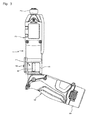
- the grip may be rotatably attached so as to be able to both extend roughly parallel to the rotation axis of the operation switch, and extend at a slant or a right angle with respect to the rotation axis of the operation switch, from the rear end of the tool body.
- the grip by placing the grip at a slant or at a right angle with respect to the rotation axis of the operation switch, it can be used as an electrical power tool of a gun-grip type, and, by placing the grip parallel to the rotation axis of the operation switch, it can be used also as an electrical power tool of a pen-grip type which can be inserted into a work space having a narrow width.
- the operation switch which is rotated around the axis parallel to the rotation axis of the tip tool, and determines the rotation direction and the rotation speed of the tip tool according to the rotation direction and the rotation angle of the operation switch, is provided, the user can intuitively grasp the operation amount of the operation switch, and finely control the speed of the tip tool.
- the grip is rotatable with respect to the tool body, whereby the electrical power tool can be used in various work spaces by changing the shape of the electrical power tool.
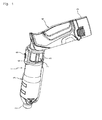
- Figs. 1 to 3 show an electrical power tool 1 of one embodiment of the present invention.
- the electrical power tool 1 has a chuck 2 which is rotatable with a tip tool such as a drill and a driver gripped, a roughly cylindrical shaped tool body 3, which is roughly coaxial with a rotation axis of the chuck 2, and a grip 4 for a user to grip, which extends downward and obliquely backward from a rear end of the tool body 3.
- the tool body 3 has an operation switch 7 having two operation protrusions 6 respectively protruded from switch openings provided on both sides in the vicinity of the rear end, and a lock switch 8 provided so as to be positioned above the operation switch 7.
- the operation protrusions 6 are protrusions, each of which extends parallel to the rotation axis of the chuck 2, and which are bilaterally symmetrically formed with the rotation axis of the chuck 2 therebetween at an angle of 180°.
- the tool body 3 has a motor (not shown) for rotating the chuck 2 built therein.
- the grip 4 detachably holds a battery 9, and is rotatably attached with respect to the tool body 3.
- the grip 4 can also deform the whole electrical power tool 1 in a roughly rod shape by being aligned in a roughly straight line with the tool body 3. This enables the electrical power tool 1. to be inserted into a work space, where work can be performed.
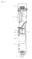
- the operation switch 7 taken out from the tool body 3 is shown in Fig. 3 .
- the operation switch 7 consists of a roughly cylindrical shaped cylinder 10 formed with the operation protrusions 6, and a switch body 11 located inside the cylinder 10 and fixed with respect to the tool body 3.
- the cylinder 10 is rotatable around the switch body 11, and is incorporated into the tool body 3 so that a rotation axis of the cylinder 10 is coaxial with the rotation axis of the chuck 2 and the tip tool held by the chuck 2. Further, the cylinder 10 has a notch 12 formed in one end of a cylinder wall.
- the operation switch 7 has an action portion 13, which is integrally rotated with the cylinder 10 inside the switch body 11.
- the switch body 11 is formed in a roughly cylindrical shape, and has an engagement portion 14 that inwardly protrudes.
- the operation switch 7 has an urging spring 15 whose central portion is wound around a rotation shaft of the cylinder 10, and whose both end portions pinch the action portion 13 and the engagement portion 14.
- the action portion 13 and the engagement portion 14 are separated to expand the both end portions of the urging spring 15 against its urging force.
- the urging spring 15 rotates the action portion 13 by its urging force so that the action portion 13 is radially aligned with the engagement portion 14, and then allow the cylinder 10 to be self-restored to a neutral position where the operation protrusions 6 become horizontal.
- the operation switch 7 has an input terminal connected to an electrode of a battery 9 attached to the grip 4, an output terminal connected to an input terminal of the motor built in the tool body 3, and a speed controlling circuit built therein, which can invert the polarity of the output terminal and vary the output voltage while controlling a current application time ratio.
- the speed controlling circuit outputs no voltage to the output terminal when the cylinder 10 is at the neutral position, so as to stop rotation of the chuck 2.
- the speed controlling circuit of the operation switch 7 outputs a voltage according to a rotation angle of the cylinder 10 with the polarity that rotates the chuck 2 right-handed.
- the chuck 2 is rotated at a speed according to the rotation angle of the cylinder 10 of the operation switch 7.
- the rotation speed of the chuck 2 when referring to the rotation speed of the chuck 2 (tip tool), it indicates an unloaded rotation speed, and does not necessarily coincide with a rotation speed when loaded.
- the speed controlling circuit of the operation switch 7 outputs a voltage to rotate the chuck 2 left-handed according to the rotation angle of the cylinder 10.
- the user can extend the user's thumb and put it on the operation protrusion 6 provided in the vicinity of the grip 4, and can also extend the user's index finger and put it on the operation protrusion 6 on the opposite side, and further can hold the operation protrusions 6 in a manner so as to pinch the operation protrusions 6 on both sides with the thumb and the index finger. That is, the user can rotate the cylinder 10 of the operation switch 7 while gripping the grip 4. Further, this is the same both when the electrical power tool 1 is gripped by the right hand and when it is gripped by the left hand and thus it is possible to handle the electrical power tool 1 by either the right or left hand.
- the user can intuitively grasp the rotation angle of the operation switch 7 based on a direction of the grip 4 that the user grips. That is, the user can easily grasp the rotation speed of the chuck 2 and finely control its rotation speed.
- a rotation axis of the operation switch 7 is coaxial with the rotation axis of the chuck 2 in the electrical power tool 1 of the present embodiment, even if the rotation axis of the operation switch 7 is not coaxial with the rotation axis of the chuck 2, there is almost no problem in operability as long as the rotation axis of the operation switch 7 is roughly parallel to the rotation axis of the chuck 2.
- the lock switch 8 is slidably provided parallel to the rotation axis of the chuck 2 and the operation switch 7, and engageable with a notch 12 formed in the cylinder 10 of the operation switch 7. That is, as shown in the figure, the lock switch 8 engages with the notch 12 by sliding to the grip 4 side when the operation switch 7 is at the neutral position, so as to construct a lock mechanism to prevent rotation of the cylinder 10 by engaging therewith.
- Preventing the rotation of the operation switch 7 by the engagement of the lock switch 8 therewith enables the chuck 2 to be kept in a stopped state. This makes it possible to prevent injury, damage to articles, and wasteful power consumption due to unintentional rotation of the tip tool caused by a contact of the electrical power tool 1 with a floor or surrounding objects, so that the operation switch 7 is accidentally operated.
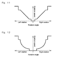
- Fig. 11 shows a relationship between the rotation angle of the operation switch 7 and the rotation speed of the chuck in the electrical power tool 1.
- the operation switch when the operation switch is at the neutral position, an electrical path is opened between the input terminal and the output terminal of the speed controlling circuit so as not to output a voltage.
- the operation switch 7 When the operation switch 7 is rotated by a few degrees, the input terminal and the output terminal of the speed controlling circuit are connected via a switching element for opening/closing them at a specific time ratio.
- a variable resistance value of a variable resistor is changed so that the closed time of the switching element becomes longer in proportion to the rotation angle of the operation switch 7.
- the switching element when the operation switch 7 is rotated by about 30°, the switching element is continuously turned on so that the chuck 2 is rotated at a maximum speed. By this, the user can almost linearly control the rotation number of the tip tool.
- the relationship between the rotation angle of the operation switch 7 and the rotation speed of the chuck 2 may acceleratingly change.
- the chuck 2 (and the tip tool held therein) were rotated in the same direction as the rotation direction of the operation switch 7, for example, when operating the electrical power tool 1 by extending only the user's thumb to the operation protrusion, in some cases, the right-handed user sensibly feels it easier to use it when the rotation direction of the operation switch 7 and the rotation direction of the chuck 2 are opposite to each other. That is, in the present invention, the rotation direction of the operation switch 7 and the rotation direction of the chuck 2 may be opposite to each other. Alternatively, the relationship between the rotation direction of the operation switch 7 and the rotation direction of the chuck 2 may be reversed.
- the chuck 2 may be rotated in the forward direction even if the operation switch 7 is rotated in either direction from the neutral position.
- the present invention can be utilized for an electrical power tool for controlling the rotation direction and the rotation speed of the tip tool such as a drill, a driver bit and a grinder.
Landscapes
- Engineering & Computer Science (AREA)
- Mechanical Engineering (AREA)
- Portable Power Tools In General (AREA)
- Rotary Switch, Piano Key Switch, And Lever Switch (AREA)
Applications Claiming Priority (1)
| Application Number | Priority Date | Filing Date | Title |
|---|---|---|---|
| JP2008333662A JP4961418B2 (ja) | 2008-12-26 | 2008-12-26 | 電動工具 |
Publications (4)
| Publication Number | Publication Date |
|---|---|
| EP2202035A2 true EP2202035A2 (fr) | 2010-06-30 |
| EP2202035A8 EP2202035A8 (fr) | 2010-11-17 |
| EP2202035A3 EP2202035A3 (fr) | 2012-08-15 |
| EP2202035B1 EP2202035B1 (fr) | 2013-07-24 |
Family
ID=42103399
Family Applications (1)
| Application Number | Title | Priority Date | Filing Date |
|---|---|---|---|
| EP09180405.4A Active EP2202035B1 (fr) | 2008-12-26 | 2009-12-22 | Outil électrique |
Country Status (4)
| Country | Link |
|---|---|
| US (1) | US8276685B2 (fr) |
| EP (1) | EP2202035B1 (fr) |
| JP (1) | JP4961418B2 (fr) |
| CN (1) | CN101767329B (fr) |
Cited By (5)
| Publication number | Priority date | Publication date | Assignee | Title |
|---|---|---|---|---|
| WO2014108110A1 (fr) * | 2013-01-10 | 2014-07-17 | Alfred Raith Gmbh | Dispositif de commutation et de commande pour un outil électrique et procédé de commande dudit outil |
| EP2998073A1 (fr) * | 2014-09-10 | 2016-03-23 | Robert Bosch Gmbh | Machine-outil portative fonctionnant sur batterie ayant au moins une partie de carter moteur |
| WO2018228825A1 (fr) * | 2017-06-12 | 2018-12-20 | Atlas Copco Industrial Technique Ab | Boulonneuse mécanique à entraînement angulaire |
| EP3792006A1 (fr) * | 2019-09-12 | 2021-03-17 | Andreas Stihl AG & Co. KG | Appareil de travail portatif doté d'un outil |
| US11607794B2 (en) | 2017-06-12 | 2023-03-21 | Atlas Copco Industrial Technique Ab | Power wrench with adjustable trigger position |
Families Citing this family (17)
| Publication number | Priority date | Publication date | Assignee | Title |
|---|---|---|---|---|
| EP2289670B1 (fr) * | 2009-08-31 | 2012-07-11 | Robert Bosch GmbH | Outil rotatif électrique |
| JP5368946B2 (ja) * | 2009-11-16 | 2013-12-18 | 株式会社マキタ | 電動工具 |
| US9266230B2 (en) | 2010-01-07 | 2016-02-23 | Black & Decker Inc. | Twist-handled power tool with locking system |
| US8555999B2 (en) * | 2010-04-30 | 2013-10-15 | Black & Decker Inc. | Twist-handled power tool with locking system |
| US12059780B2 (en) * | 2010-09-30 | 2024-08-13 | Black & Decker Inc. | Lighted power tool |
| DE102012206884A1 (de) * | 2012-04-26 | 2013-10-31 | Robert Bosch Gmbh | Handwerkzeugmaschine |
| US9956676B2 (en) | 2013-01-09 | 2018-05-01 | Techtronic Power Tools Technology Limited | Tool with rotatable head |
| DE102013200576A1 (de) * | 2013-01-16 | 2014-07-17 | Robert Bosch Gmbh | Handwerkzeugmaschine mit einem ergonomischen Handgriff |
| JP6481881B2 (ja) * | 2014-08-26 | 2019-03-13 | パナソニックIpマネジメント株式会社 | 電動工具 |
| DE102015214315A1 (de) * | 2015-07-29 | 2017-02-02 | Robert Bosch Gmbh | Tragbare Werkzeugmaschine |
| JP6506669B2 (ja) * | 2015-10-06 | 2019-04-24 | アルスコーポレーション株式会社 | 刈込機 |
| JP6821346B2 (ja) * | 2016-07-11 | 2021-01-27 | 京セラインダストリアルツールズ株式会社 | 電動ドライバ |
| DE102018121536B3 (de) * | 2018-09-04 | 2020-02-13 | Wiha Werkzeuge Gmbh | Schaltvorrichtung, Handwerkzeug und Verwendung einer Schaltvorrichtung |
| US11498198B2 (en) * | 2019-08-20 | 2022-11-15 | The Boeing Company | Ergonomic handle for a power tool |
| US11504829B2 (en) * | 2020-03-19 | 2022-11-22 | Joseph Pannone | Powered socket wrench assembly |
| JP7600542B2 (ja) * | 2020-05-20 | 2024-12-17 | オムロン株式会社 | ネジ締め不良判定装置 |
| US20220023957A1 (en) * | 2020-07-22 | 2022-01-27 | Angel Botello | Sheet Metal Tooling Assembly |
Citations (2)
| Publication number | Priority date | Publication date | Assignee | Title |
|---|---|---|---|---|
| JP3768400B2 (ja) | 2000-11-17 | 2006-04-19 | 佐鳥エス・テック株式会社 | 電動工具スイッチ |
| JP2006218560A (ja) | 2005-02-09 | 2006-08-24 | Satori S-Tech Co Ltd | トリガースイッチ |
Family Cites Families (26)
| Publication number | Priority date | Publication date | Assignee | Title |
|---|---|---|---|---|
| US3430707A (en) * | 1967-10-17 | 1969-03-04 | Singer Co | Reversible hammer drill mechanisms |
| US3511947A (en) * | 1968-01-03 | 1970-05-12 | Mc Graw Edison Co | Combination safety lock-switch mechanism for power tool |
| JPS6176285A (ja) * | 1984-09-22 | 1986-04-18 | 大協エンジニアリング株式会社 | 関節部を有する電動器具及び関節スイツチ |
| DE3524614A1 (de) * | 1985-07-10 | 1987-01-15 | Bosch Gmbh Robert | Handwerkzeugmaschine fuer rechts- und linkslauf |
| JPS62124882A (ja) * | 1985-11-25 | 1987-06-06 | 松下電工株式会社 | 電動ドライバ− |
| US4772765A (en) * | 1987-02-12 | 1988-09-20 | Black & Decker Inc. | Combined on/off and reversing switch and electric device therewith |
| US4759240A (en) * | 1987-04-28 | 1988-07-26 | Samson Lin | Electric screwdriver with adjustable joint |
| JPH0645343Y2 (ja) * | 1987-12-23 | 1994-11-24 | 松下電工株式会社 | 電動工具 |
| NL8800366A (nl) * | 1988-02-15 | 1989-09-01 | Emerson Electric Co | Montage-inrichting voor borstels bij een omkeerbare collectormotor. |
| ATE117473T1 (de) * | 1989-07-15 | 1995-02-15 | Kress Elektrik Gmbh & Co | Schaltvorrichtung für elektrische umschaltung von elektrowerkzeugen. |
| US5089729A (en) * | 1991-03-14 | 1992-02-18 | Black & Decker Inc. | Power tool with brush shifting and reversing switch assembly |
| DE4128651A1 (de) | 1991-08-29 | 1993-03-04 | Gardena Kress & Kastner Gmbh | Elektroschrauber |
| US5225727A (en) * | 1991-09-20 | 1993-07-06 | Ingersoll-Rand Company | Reverse switch assembly |
| KR100306734B1 (ko) | 1993-04-05 | 2001-11-30 | 배리 이. 도이치 | 무선장치용배터리팩 |
| US6039126A (en) * | 1998-05-15 | 2000-03-21 | Hsieh; An-Fu | Multi-usage electric tool with angle-changeable grip |
| US6102134A (en) * | 1998-10-16 | 2000-08-15 | Black & Decker Inc. | Two-position screwdriver |
| US6273200B1 (en) * | 1999-07-07 | 2001-08-14 | Black & Decker Inc. | Screwdriver with manuel spindel lock |
| JP2006321043A (ja) * | 2005-05-17 | 2006-11-30 | Milwaukee Electric Tool Corp | 動力工具、バッテリ、充電器、およびそれらを動作させる方法 |
| CN1891414A (zh) * | 2005-05-17 | 2007-01-10 | 密尔沃基电动工具公司 | 电动工具,蓄电池组,充电器及其操作方法 |
| JP2006325395A (ja) * | 2005-05-17 | 2006-11-30 | Milwaukee Electric Tool Corp | 動力工具、バッテリ、充電器、およびそれらを動作させる方法 |
| DE602006013863D1 (de) * | 2005-11-04 | 2010-06-02 | Bosch Gmbh Robert | Verfahren und vorrichtung für einen gelenkbohrer |
| JP2007276038A (ja) * | 2006-04-05 | 2007-10-25 | Hitachi Koki Co Ltd | 電動工具 |
| JP4669455B2 (ja) | 2006-08-31 | 2011-04-13 | パナソニック電工株式会社 | 電動工具 |
| JP2008055563A (ja) * | 2006-08-31 | 2008-03-13 | Matsushita Electric Works Ltd | 電動工具 |
| CN201128147Y (zh) * | 2007-12-25 | 2008-10-08 | 强纲工业股份有限公司 | 速度切换保护装置 |
| CN201320736Y (zh) * | 2008-11-25 | 2009-10-07 | 南京德朔实业有限公司 | 冲击螺丝批 |
-
2008
- 2008-12-26 JP JP2008333662A patent/JP4961418B2/ja active Active
-
2009
- 2009-12-21 US US12/643,446 patent/US8276685B2/en active Active
- 2009-12-22 EP EP09180405.4A patent/EP2202035B1/fr active Active
- 2009-12-24 CN CN2009102663291A patent/CN101767329B/zh active Active
Patent Citations (2)
| Publication number | Priority date | Publication date | Assignee | Title |
|---|---|---|---|---|
| JP3768400B2 (ja) | 2000-11-17 | 2006-04-19 | 佐鳥エス・テック株式会社 | 電動工具スイッチ |
| JP2006218560A (ja) | 2005-02-09 | 2006-08-24 | Satori S-Tech Co Ltd | トリガースイッチ |
Cited By (10)
| Publication number | Priority date | Publication date | Assignee | Title |
|---|---|---|---|---|
| WO2014108110A1 (fr) * | 2013-01-10 | 2014-07-17 | Alfred Raith Gmbh | Dispositif de commutation et de commande pour un outil électrique et procédé de commande dudit outil |
| EP2998073A1 (fr) * | 2014-09-10 | 2016-03-23 | Robert Bosch Gmbh | Machine-outil portative fonctionnant sur batterie ayant au moins une partie de carter moteur |
| WO2018228825A1 (fr) * | 2017-06-12 | 2018-12-20 | Atlas Copco Industrial Technique Ab | Boulonneuse mécanique à entraînement angulaire |
| US11273540B2 (en) | 2017-06-12 | 2022-03-15 | Atlas Copco Industrial Technique Ab | Power wrench with angle drive |
| US11607794B2 (en) | 2017-06-12 | 2023-03-21 | Atlas Copco Industrial Technique Ab | Power wrench with adjustable trigger position |
| EP3792006A1 (fr) * | 2019-09-12 | 2021-03-17 | Andreas Stihl AG & Co. KG | Appareil de travail portatif doté d'un outil |
| EP3792009A1 (fr) * | 2019-09-12 | 2021-03-17 | Andreas Stihl AG & Co. KG | Appareil de travail portatif doté d'un outil |
| EP3792008A1 (fr) * | 2019-09-12 | 2021-03-17 | Andreas Stihl AG & Co. KG | Appareil de travail portatif doté d'un outil |
| US11958155B2 (en) | 2019-09-12 | 2024-04-16 | Andreas Stihl Ag & Co. Kg | Handheld work apparatus having a work tool |
| US12330257B2 (en) | 2019-09-12 | 2025-06-17 | Andreas Stihl Ag & Co. Kg | Handheld work apparatus having a work tool |
Also Published As
| Publication number | Publication date |
|---|---|
| US8276685B2 (en) | 2012-10-02 |
| EP2202035A3 (fr) | 2012-08-15 |
| CN101767329A (zh) | 2010-07-07 |
| US20100163265A1 (en) | 2010-07-01 |
| EP2202035B1 (fr) | 2013-07-24 |
| EP2202035A8 (fr) | 2010-11-17 |
| CN101767329B (zh) | 2012-07-18 |
| JP4961418B2 (ja) | 2012-06-27 |
| JP2010155294A (ja) | 2010-07-15 |
Similar Documents
| Publication | Publication Date | Title |
|---|---|---|
| EP2202035B1 (fr) | Outil électrique | |
| JP5256151B2 (ja) | 刈払機 | |
| CN102848358B (zh) | 手持式工具机,特别是钻孔机或者起子机 | |
| EP2422934B1 (fr) | Outils électriques portables | |
| EP2199033B1 (fr) | Outil à main électrique | |
| EP2202771A1 (fr) | Commutateur d'outil électrique | |
| EP3503145B1 (fr) | Système de verrouillage destiné à être utilisé avec un ensemble de déclenchement d'un dispositif électrique | |
| CN112548954A (zh) | 手持式工具机 | |
| EP2709133A1 (fr) | Déclencheur et outil électrique | |
| CN112548956A (zh) | 手持式工具机和用于运行手持式工具机的方法 | |
| EP3141357B1 (fr) | Ciseaux électriques | |
| JP2008183691A (ja) | 電動工具 | |
| JP2016175148A (ja) | 電動工具 | |
| CN118061136A (zh) | 用于动力工具的方向选择器机构及工具 | |
| US7261166B2 (en) | Switch for power tool | |
| CN112548953A (zh) | 手持式工具机 | |
| JP6481881B2 (ja) | 電動工具 | |
| JP2011136405A (ja) | 電動工具 | |
| AU2021282449A1 (en) | Hand held rotary power tool | |
| CN111542417B (zh) | 工具机设备 | |
| EP1875988A1 (fr) | Clé électrique | |
| JP2013138689A (ja) | 刈払機 | |
| JP5403477B2 (ja) | 電動工具 | |
| JP2020049553A (ja) | 電動工具 | |
| JPS62120986A (ja) | 回転工具 |
Legal Events
| Date | Code | Title | Description |
|---|---|---|---|
| PUAI | Public reference made under article 153(3) epc to a published international application that has entered the european phase |
Free format text: ORIGINAL CODE: 0009012 |
|
| AK | Designated contracting states |
Kind code of ref document: A2 Designated state(s): AT BE BG CH CY CZ DE DK EE ES FI FR GB GR HR HU IE IS IT LI LT LU LV MC MK MT NL NO PL PT RO SE SI SK SM TR |
|
| AX | Request for extension of the european patent |
Extension state: AL BA RS |
|
| RAP1 | Party data changed (applicant data changed or rights of an application transferred) |
Owner name: OMRON CORPORATION Owner name: MAKITA CORPORATION |
|
| RIN1 | Information on inventor provided before grant (corrected) |
Inventor name: MIYAURA, HIROYUKI Inventor name: NISHIKIMI, JUNICHI Inventor name: TOMONAGA, AKIRA Inventor name: BABA, YOSHIYUKI Inventor name: HOZUMI, AKIHIRO Inventor name: OMORI, KOJI |
|
| PUAL | Search report despatched |
Free format text: ORIGINAL CODE: 0009013 |
|
| AK | Designated contracting states |
Kind code of ref document: A3 Designated state(s): AT BE BG CH CY CZ DE DK EE ES FI FR GB GR HR HU IE IS IT LI LT LU LV MC MK MT NL NO PL PT RO SE SI SK SM TR |
|
| AX | Request for extension of the european patent |
Extension state: AL BA RS |
|
| RIC1 | Information provided on ipc code assigned before grant |
Ipc: B25F 5/00 20060101AFI20120712BHEP Ipc: B25B 21/00 20060101ALI20120712BHEP |
|
| 17P | Request for examination filed |
Effective date: 20120924 |
|
| GRAP | Despatch of communication of intention to grant a patent |
Free format text: ORIGINAL CODE: EPIDOSNIGR1 |
|
| GRAS | Grant fee paid |
Free format text: ORIGINAL CODE: EPIDOSNIGR3 |
|
| GRAA | (expected) grant |
Free format text: ORIGINAL CODE: 0009210 |
|
| AK | Designated contracting states |
Kind code of ref document: B1 Designated state(s): AT BE BG CH CY CZ DE DK EE ES FI FR GB GR HR HU IE IS IT LI LT LU LV MC MK MT NL NO PL PT RO SE SI SK SM TR |
|
| REG | Reference to a national code |
Ref country code: GB Ref legal event code: FG4D |
|
| RIN1 | Information on inventor provided before grant (corrected) |
Inventor name: NISHIKIMI, JUNICHI Inventor name: OMORI, KOJI Inventor name: TOMONAGA, AKIRA Inventor name: BABA, YOSHIYUKI Inventor name: HOZUMI, AKIHIRO Inventor name: MIYAURA, HIROYUKI |
|
| REG | Reference to a national code |
Ref country code: CH Ref legal event code: EP |
|
| REG | Reference to a national code |
Ref country code: AT Ref legal event code: REF Ref document number: 623121 Country of ref document: AT Kind code of ref document: T Effective date: 20130815 |
|
| REG | Reference to a national code |
Ref country code: IE Ref legal event code: FG4D |
|
| REG | Reference to a national code |
Ref country code: DE Ref legal event code: R096 Ref document number: 602009017378 Country of ref document: DE Effective date: 20130919 |
|
| REG | Reference to a national code |
Ref country code: AT Ref legal event code: MK05 Ref document number: 623121 Country of ref document: AT Kind code of ref document: T Effective date: 20130724 |
|
| REG | Reference to a national code |
Ref country code: NL Ref legal event code: VDEP Effective date: 20130724 |
|
| REG | Reference to a national code |
Ref country code: LT Ref legal event code: MG4D |
|
| PG25 | Lapsed in a contracting state [announced via postgrant information from national office to epo] |
Ref country code: CY Free format text: LAPSE BECAUSE OF FAILURE TO SUBMIT A TRANSLATION OF THE DESCRIPTION OR TO PAY THE FEE WITHIN THE PRESCRIBED TIME-LIMIT Effective date: 20130828 Ref country code: HR Free format text: LAPSE BECAUSE OF FAILURE TO SUBMIT A TRANSLATION OF THE DESCRIPTION OR TO PAY THE FEE WITHIN THE PRESCRIBED TIME-LIMIT Effective date: 20130724 Ref country code: IS Free format text: LAPSE BECAUSE OF FAILURE TO SUBMIT A TRANSLATION OF THE DESCRIPTION OR TO PAY THE FEE WITHIN THE PRESCRIBED TIME-LIMIT Effective date: 20131124 Ref country code: BE Free format text: LAPSE BECAUSE OF FAILURE TO SUBMIT A TRANSLATION OF THE DESCRIPTION OR TO PAY THE FEE WITHIN THE PRESCRIBED TIME-LIMIT Effective date: 20130724 Ref country code: PT Free format text: LAPSE BECAUSE OF FAILURE TO SUBMIT A TRANSLATION OF THE DESCRIPTION OR TO PAY THE FEE WITHIN THE PRESCRIBED TIME-LIMIT Effective date: 20131125 Ref country code: SE Free format text: LAPSE BECAUSE OF FAILURE TO SUBMIT A TRANSLATION OF THE DESCRIPTION OR TO PAY THE FEE WITHIN THE PRESCRIBED TIME-LIMIT Effective date: 20130724 Ref country code: AT Free format text: LAPSE BECAUSE OF FAILURE TO SUBMIT A TRANSLATION OF THE DESCRIPTION OR TO PAY THE FEE WITHIN THE PRESCRIBED TIME-LIMIT Effective date: 20130724 Ref country code: NO Free format text: LAPSE BECAUSE OF FAILURE TO SUBMIT A TRANSLATION OF THE DESCRIPTION OR TO PAY THE FEE WITHIN THE PRESCRIBED TIME-LIMIT Effective date: 20131024 Ref country code: LT Free format text: LAPSE BECAUSE OF FAILURE TO SUBMIT A TRANSLATION OF THE DESCRIPTION OR TO PAY THE FEE WITHIN THE PRESCRIBED TIME-LIMIT Effective date: 20130724 |
|
| PG25 | Lapsed in a contracting state [announced via postgrant information from national office to epo] |
Ref country code: SI Free format text: LAPSE BECAUSE OF FAILURE TO SUBMIT A TRANSLATION OF THE DESCRIPTION OR TO PAY THE FEE WITHIN THE PRESCRIBED TIME-LIMIT Effective date: 20130724 Ref country code: GR Free format text: LAPSE BECAUSE OF FAILURE TO SUBMIT A TRANSLATION OF THE DESCRIPTION OR TO PAY THE FEE WITHIN THE PRESCRIBED TIME-LIMIT Effective date: 20131025 Ref country code: PL Free format text: LAPSE BECAUSE OF FAILURE TO SUBMIT A TRANSLATION OF THE DESCRIPTION OR TO PAY THE FEE WITHIN THE PRESCRIBED TIME-LIMIT Effective date: 20130724 Ref country code: FI Free format text: LAPSE BECAUSE OF FAILURE TO SUBMIT A TRANSLATION OF THE DESCRIPTION OR TO PAY THE FEE WITHIN THE PRESCRIBED TIME-LIMIT Effective date: 20130724 Ref country code: NL Free format text: LAPSE BECAUSE OF FAILURE TO SUBMIT A TRANSLATION OF THE DESCRIPTION OR TO PAY THE FEE WITHIN THE PRESCRIBED TIME-LIMIT Effective date: 20130724 Ref country code: LV Free format text: LAPSE BECAUSE OF FAILURE TO SUBMIT A TRANSLATION OF THE DESCRIPTION OR TO PAY THE FEE WITHIN THE PRESCRIBED TIME-LIMIT Effective date: 20130724 |
|
| PG25 | Lapsed in a contracting state [announced via postgrant information from national office to epo] |
Ref country code: CY Free format text: LAPSE BECAUSE OF FAILURE TO SUBMIT A TRANSLATION OF THE DESCRIPTION OR TO PAY THE FEE WITHIN THE PRESCRIBED TIME-LIMIT Effective date: 20130724 |
|
| PG25 | Lapsed in a contracting state [announced via postgrant information from national office to epo] |
Ref country code: SK Free format text: LAPSE BECAUSE OF FAILURE TO SUBMIT A TRANSLATION OF THE DESCRIPTION OR TO PAY THE FEE WITHIN THE PRESCRIBED TIME-LIMIT Effective date: 20130724 Ref country code: DK Free format text: LAPSE BECAUSE OF FAILURE TO SUBMIT A TRANSLATION OF THE DESCRIPTION OR TO PAY THE FEE WITHIN THE PRESCRIBED TIME-LIMIT Effective date: 20130724 Ref country code: EE Free format text: LAPSE BECAUSE OF FAILURE TO SUBMIT A TRANSLATION OF THE DESCRIPTION OR TO PAY THE FEE WITHIN THE PRESCRIBED TIME-LIMIT Effective date: 20130724 Ref country code: RO Free format text: LAPSE BECAUSE OF FAILURE TO SUBMIT A TRANSLATION OF THE DESCRIPTION OR TO PAY THE FEE WITHIN THE PRESCRIBED TIME-LIMIT Effective date: 20130724 Ref country code: CZ Free format text: LAPSE BECAUSE OF FAILURE TO SUBMIT A TRANSLATION OF THE DESCRIPTION OR TO PAY THE FEE WITHIN THE PRESCRIBED TIME-LIMIT Effective date: 20130724 |
|
| PG25 | Lapsed in a contracting state [announced via postgrant information from national office to epo] |
Ref country code: ES Free format text: LAPSE BECAUSE OF FAILURE TO SUBMIT A TRANSLATION OF THE DESCRIPTION OR TO PAY THE FEE WITHIN THE PRESCRIBED TIME-LIMIT Effective date: 20130724 |
|
| PLBE | No opposition filed within time limit |
Free format text: ORIGINAL CODE: 0009261 |
|
| STAA | Information on the status of an ep patent application or granted ep patent |
Free format text: STATUS: NO OPPOSITION FILED WITHIN TIME LIMIT |
|
| 26N | No opposition filed |
Effective date: 20140425 |
|
| REG | Reference to a national code |
Ref country code: CH Ref legal event code: PL |
|
| REG | Reference to a national code |
Ref country code: DE Ref legal event code: R097 Ref document number: 602009017378 Country of ref document: DE Effective date: 20140425 |
|
| PG25 | Lapsed in a contracting state [announced via postgrant information from national office to epo] |
Ref country code: MC Free format text: LAPSE BECAUSE OF FAILURE TO SUBMIT A TRANSLATION OF THE DESCRIPTION OR TO PAY THE FEE WITHIN THE PRESCRIBED TIME-LIMIT Effective date: 20130724 Ref country code: LU Free format text: LAPSE BECAUSE OF FAILURE TO SUBMIT A TRANSLATION OF THE DESCRIPTION OR TO PAY THE FEE WITHIN THE PRESCRIBED TIME-LIMIT Effective date: 20131222 |
|
| REG | Reference to a national code |
Ref country code: IE Ref legal event code: MM4A |
|
| PG25 | Lapsed in a contracting state [announced via postgrant information from national office to epo] |
Ref country code: CH Free format text: LAPSE BECAUSE OF NON-PAYMENT OF DUE FEES Effective date: 20131231 Ref country code: LI Free format text: LAPSE BECAUSE OF NON-PAYMENT OF DUE FEES Effective date: 20131231 Ref country code: IE Free format text: LAPSE BECAUSE OF NON-PAYMENT OF DUE FEES Effective date: 20131222 |
|
| PG25 | Lapsed in a contracting state [announced via postgrant information from national office to epo] |
Ref country code: SM Free format text: LAPSE BECAUSE OF FAILURE TO SUBMIT A TRANSLATION OF THE DESCRIPTION OR TO PAY THE FEE WITHIN THE PRESCRIBED TIME-LIMIT Effective date: 20130724 |
|
| PG25 | Lapsed in a contracting state [announced via postgrant information from national office to epo] |
Ref country code: TR Free format text: LAPSE BECAUSE OF FAILURE TO SUBMIT A TRANSLATION OF THE DESCRIPTION OR TO PAY THE FEE WITHIN THE PRESCRIBED TIME-LIMIT Effective date: 20130724 |
|
| PG25 | Lapsed in a contracting state [announced via postgrant information from national office to epo] |
Ref country code: HU Free format text: LAPSE BECAUSE OF FAILURE TO SUBMIT A TRANSLATION OF THE DESCRIPTION OR TO PAY THE FEE WITHIN THE PRESCRIBED TIME-LIMIT; INVALID AB INITIO Effective date: 20091222 Ref country code: MK Free format text: LAPSE BECAUSE OF FAILURE TO SUBMIT A TRANSLATION OF THE DESCRIPTION OR TO PAY THE FEE WITHIN THE PRESCRIBED TIME-LIMIT Effective date: 20130724 Ref country code: BG Free format text: LAPSE BECAUSE OF FAILURE TO SUBMIT A TRANSLATION OF THE DESCRIPTION OR TO PAY THE FEE WITHIN THE PRESCRIBED TIME-LIMIT Effective date: 20130724 |
|
| PG25 | Lapsed in a contracting state [announced via postgrant information from national office to epo] |
Ref country code: MT Free format text: LAPSE BECAUSE OF FAILURE TO SUBMIT A TRANSLATION OF THE DESCRIPTION OR TO PAY THE FEE WITHIN THE PRESCRIBED TIME-LIMIT Effective date: 20130724 |
|
| REG | Reference to a national code |
Ref country code: FR Ref legal event code: PLFP Year of fee payment: 7 |
|
| REG | Reference to a national code |
Ref country code: FR Ref legal event code: PLFP Year of fee payment: 8 |
|
| REG | Reference to a national code |
Ref country code: FR Ref legal event code: PLFP Year of fee payment: 9 |
|
| PGFP | Annual fee paid to national office [announced via postgrant information from national office to epo] |
Ref country code: DE Payment date: 20251028 Year of fee payment: 17 |
|
| PGFP | Annual fee paid to national office [announced via postgrant information from national office to epo] |
Ref country code: GB Payment date: 20251030 Year of fee payment: 17 |
|
| PGFP | Annual fee paid to national office [announced via postgrant information from national office to epo] |
Ref country code: IT Payment date: 20251121 Year of fee payment: 17 |
|
| PGFP | Annual fee paid to national office [announced via postgrant information from national office to epo] |
Ref country code: FR Payment date: 20251110 Year of fee payment: 17 |