EP2202529A2 - Testen eines Kabels mit verdrilltem Adernpaar - Google Patents
Testen eines Kabels mit verdrilltem Adernpaar Download PDFInfo
- Publication number
- EP2202529A2 EP2202529A2 EP09252878A EP09252878A EP2202529A2 EP 2202529 A2 EP2202529 A2 EP 2202529A2 EP 09252878 A EP09252878 A EP 09252878A EP 09252878 A EP09252878 A EP 09252878A EP 2202529 A2 EP2202529 A2 EP 2202529A2
- Authority
- EP
- European Patent Office
- Prior art keywords
- magnetic field
- electrical cable
- cable
- relative motion
- twisted
- Prior art date
- Legal status (The legal status is an assumption and is not a legal conclusion. Google has not performed a legal analysis and makes no representation as to the accuracy of the status listed.)
- Granted
Links
- 238000012360 testing method Methods 0.000 title description 3
- 230000005291 magnetic effect Effects 0.000 claims abstract description 73
- 230000007547 defect Effects 0.000 claims abstract description 20
- 238000000034 method Methods 0.000 claims abstract description 18
- 238000007689 inspection Methods 0.000 claims abstract description 8
- 230000002950 deficient Effects 0.000 claims description 5
- 239000012141 concentrate Substances 0.000 claims 1
- 230000001419 dependent effect Effects 0.000 claims 1
- 230000004044 response Effects 0.000 abstract description 2
- 230000005284 excitation Effects 0.000 description 4
- 230000004907 flux Effects 0.000 description 4
- 238000001514 detection method Methods 0.000 description 3
- 230000005294 ferromagnetic effect Effects 0.000 description 3
- 238000009413 insulation Methods 0.000 description 3
- 238000004519 manufacturing process Methods 0.000 description 3
- 238000002360 preparation method Methods 0.000 description 3
- 230000008859 change Effects 0.000 description 2
- 239000004020 conductor Substances 0.000 description 2
- 230000007423 decrease Effects 0.000 description 2
- 238000010586 diagram Methods 0.000 description 2
- 230000005292 diamagnetic effect Effects 0.000 description 2
- 238000012544 monitoring process Methods 0.000 description 2
- 229920003023 plastic Polymers 0.000 description 2
- 239000004033 plastic Substances 0.000 description 2
- 230000001360 synchronised effect Effects 0.000 description 2
- RYGMFSIKBFXOCR-UHFFFAOYSA-N Copper Chemical compound [Cu] RYGMFSIKBFXOCR-UHFFFAOYSA-N 0.000 description 1
- 230000004913 activation Effects 0.000 description 1
- 229910052802 copper Inorganic materials 0.000 description 1
- 239000010949 copper Substances 0.000 description 1
- 230000008878 coupling Effects 0.000 description 1
- 238000010168 coupling process Methods 0.000 description 1
- 238000005859 coupling reaction Methods 0.000 description 1
- 230000001066 destructive effect Effects 0.000 description 1
- 239000003989 dielectric material Substances 0.000 description 1
- 230000000694 effects Effects 0.000 description 1
- 230000005670 electromagnetic radiation Effects 0.000 description 1
- 238000005538 encapsulation Methods 0.000 description 1
- 238000011156 evaluation Methods 0.000 description 1
- 238000001125 extrusion Methods 0.000 description 1
- 239000000463 material Substances 0.000 description 1
- 238000012986 modification Methods 0.000 description 1
- 230000004048 modification Effects 0.000 description 1
- 229920002635 polyurethane Polymers 0.000 description 1
- 239000004814 polyurethane Substances 0.000 description 1
- 230000008569 process Effects 0.000 description 1
- 238000012216 screening Methods 0.000 description 1
- 238000011896 sensitive detection Methods 0.000 description 1
- 238000010624 twisted pair cabling Methods 0.000 description 1
Images
Classifications
-
- G—PHYSICS
- G01—MEASURING; TESTING
- G01R—MEASURING ELECTRIC VARIABLES; MEASURING MAGNETIC VARIABLES
- G01R31/00—Arrangements for testing electric properties; Arrangements for locating electric faults; Arrangements for electrical testing characterised by what is being tested not provided for elsewhere
- G01R31/50—Testing of electric apparatus, lines, cables or components for short-circuits, continuity, leakage current or incorrect line connections
- G01R31/58—Testing of lines, cables or conductors
- G01R31/59—Testing of lines, cables or conductors while the cable continuously passes the testing apparatus, e.g. during manufacture
-
- G—PHYSICS
- G01—MEASURING; TESTING
- G01R—MEASURING ELECTRIC VARIABLES; MEASURING MAGNETIC VARIABLES
- G01R31/00—Arrangements for testing electric properties; Arrangements for locating electric faults; Arrangements for electrical testing characterised by what is being tested not provided for elsewhere
- G01R31/08—Locating faults in cables, transmission lines, or networks
- G01R31/081—Locating faults in cables, transmission lines, or networks according to type of conductors
- G01R31/083—Locating faults in cables, transmission lines, or networks according to type of conductors in cables, e.g. underground
Definitions
- the present invention relates generally to cable inspection, and specifically to inspection of twisted-pair electrical cable.
- Wire manufacturers typically produce electrical wire in long, continuous lengths.
- the wire is normally wound on spools for sale to wire suppliers or customers. It is not uncommon for wire to break during the wire manufacturing process. When this occurs, the manufacturer usually splices the wire back together and the manufacturing process continues. When the breakage of an insulated electrical wire occurs, the manufacturer usually trims back the insulation on either side of the break and welds the two ends of the conductor together. Since it is not uncommon for several breaks to occur during a given production run, there may be several splices on a particular spool of wire, especially a spool containing several thousand feet of wire. Wire splices may also occur during insulation application, and may be caused by extrusion or tape wrapping.
- Twisted-pair cabling is a form of wiring in which two conductors, or two halves of a single circuit, are wound together for the purposes of canceling out electromagnetic interference from external sources. Twisting wires decreases interference since the loop area between the wires, which determines the magnetic coupling into the signal, is reduced. In balanced pair operation, the two wires typically carry equal and opposite signals, which are combined at the destination. Electromagnetic radiations of the wires mutually interfere and are canceled since they are 180 degrees out of phase.
- a method for cable inspection including generating a relative motion between an electrical cable including multiple wires and a magnetic field.
- An electrical signal induced in the wires is sensed and measured responsively to a magnetic field when relative motion occurs between the wire and the coil. Variations in the electrical signal are detected, wherein the variations correspond to defects in the cable.
- an apparatus for cable inspection including:
- an apparatus for cable inspection including:
- Embodiments of the present invention provide improved methods, products and systems for inspecting twisted-pair electrical cable.
- evaluation of twisted-pair electrical cable was typically performed in a destructive manner, by unraveling the cable from its shield, isolating individual pairs of twisted wires within the cable, and then counting the twists, in some cases using a microscope.
- an X-ray machine with a needle-hole anode has also been used to image twisted pairs of electrical wires within cables, but has typically been unable to display clear images of the wires due to screening of the wires by the shield and by the presence of multiple pairs of twisted wires.
- a magnetic field generator produces a concentrated magnetic field.
- a ferromagnetic torus with a gap may be driven by an excitation coil to generate a concentrated magnetic field in the gap.
- a power generator provides alternating current through an excitation coil to generate a magnetic field focus in the torus.
- the edges of the torus adjacent to the gap may be sharpened to give enhanced concentration of the lines of flux.
- other types of magnetic field generators may be used for this purpose.
- Twisted-pair electrical cable comprising multiple wires is conveyed along a path through the magnetic field focus, via the gap in the torus, for example. That is to say, a relative motion is generated between the cable and the magnetic field.
- the cable may be conveyed using an automated conveyor or may be pulled through the gap manually, and is thus subjected to the magnetic field.
- the wires of the cable are typically connected across a differential amplifier at the end of the cable, in order to amplify the differential electrical signal that is generated between the wires due to the effect of the magnetic field.
- a monitor such as an oscilloscope, is connected to the amplifier and is used to measure an electrical signal such as the net voltage induced between paired wires in the cable.
- the particular instrumentation disclosed herein is not critical, and many known monitors are suitable for continually measuring the electrical signal between the wires.
- Each paired half-twist of wires behaves as a loop antenna, and produces a voltage whose phase is opposite to that of its fellow when subjected to the magnetic field. That is to say, in a homogeneous magnetic field, the respective voltages of the paired wires normally cancel each other, producing no net voltage across the two wires.
- the monitor senses a variation in the electrical signal due to the motion, in phase with the excitation current.
- Standard twisted-pair electrical cable normally has a uniform pitch, and the voltage signal detected by the monitor should therefore have uniform amplitude and phase. However, if the twists in the cable are incorrectly spread in a non-uniform fashion at some location in the cable, the electrical signal varies from a norm as the cable is conveyed through the magnetic field. The monitor detects this variation, which is thereupon interpreted as a defect of the twisted-pair electrical cable.
- a data acquisition unit may be connected to the monitor to automatically report the electrical signal and the detection of the defect.
- Defects in twisted-pair electrical cable may be caused when the twists are unraveled during the process of shielding encapsulation. Another cause of defects is that manufacturers of twisted-pair electrical cable typically twist the bundle of paired wires in the opposite direction of the twists of the individual wire pairs. Twisting in this fashion may unravel an individual pair of wires, thus causing the effective number of twists per inch to decrease.
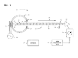
- Fig. 1 is a block diagram that schematically illustrates a system 20 for inspecting twisted-pair electrical cable, in accordance with an embodiment of the present invention.
- System 20 comprises a twisted-pair electrical cable 22, a ferromagnetic torus 24, a differential amplifier 34, and a voltage monitor 36.
- Twisted-pair electrical cable 22 comprises pairs of electrically conductive cable, wound together over the length of the cable, and coated with a shield 38.
- a current embodiment of system 20 operates effectively as long as shield 38 is not ferromagnetic. (In the case of a shield that is magnetically hardened, system 20 is typically more effective if the shield is first removed).
- Twisted-pair electrical cable 22 is typically grounded by a chassis 40.
- a magnetic field is concentrated in a gap in torus 24 by an exciting coil 32 powered by a power generator 30, producing a magnetic field focus 26.
- the edges of torus 24 may be sharpened to provide enhanced concentration of the flux lines. That is to say, a magnetic field is concentrated in a location, herein magnetic field focus 26, which is associated with a magnetic field generator. Operating the magnetic field generator produces the magnetic field.
- Twisted-pair electrical cable 22 comprising multiple wires 62, 64, has a trailing end 56, and a leading end 58. Trailing end 56 and leading end 58 are labels of twisted-pair electrical cable 22 that are assigned arbitrarily in order to denote opposite ends of the cable. Trailing end 56 of twisted-pair electrical cable 22 is "shorted," i.e., it is stripped of shield 38 and wires 62 and 64 are connected together. Leading end 58 of twisted-pair electrical cable 22 is connected to amplifier 34, completing a circuit for the purpose of monitoring the magnetic field by monitor 36.
- a suitable conveyance device shown schematically as a conveyor 27, moves twisted-pair electrical cable 22 through magnetic field focus 26, guided by diamagnetic shoulders 28.
- Diamagnetic shoulders 28 are typically made of a plastic material and guide twisted-pair electrical cable 22 precisely through magnetic field focus 26.
- the conveyance device may be conveyed manually, e.g., by a person rather than by a machine, through magnetic field focus 26.
- operation of embodiments of the present invention is not limited to a particular method of generating a relative motion between twisted-pair electrical cable 22 and magnetic field focus 26, and that any other suitable method that accomplishes relative motion of twisted-pair electrical cable 22 with respect to magnetic field focus 26 may be used.
- a movable torus could be conveyed along the cable to achieve the relative motion.
- An arrow 42 displays a direction of the movement of twisted-pair electrical cable 22. Twisted-pair electrical cable 22 is shown moving in the direction displayed by arrow 42, although embodiments of the present invention are not limited to movement in that direction.
- Monitor 36 measures an electrical signal that is induced in the wires of twisted-pair electrical cable 22 in response to relative motion between twisted-pair electrical cable 22 and magnetic field focus 26 and any signal variations thereof.
- a data acquisition unit 54 may be connected to monitor 36. Data acquisition unit 54 correlates the momentary electrical signal with locations in the electrical cable 22, and interprets certain signal variations in the monitored signal as location-specific defects in twisted-pair electrical cable 22. For example, detection of a signal variation may locate a flaw in a particular twist of the wires of twisted-pair electrical cable 22. Data acquisition unit 54 may report the defect and may also store data delineating the location of a defective part of twisted-pair electrical cable 22. Alternatively, any suitable method known in the art may be used to detect signal variations and to report defects. In the context of the present patent application and in the claims, the term "signal variation" refers to a change (typically an increase) in the amplitude of the monitored signal or to a change in the length of time between phase alternations in the monitored signal.
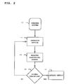
- Fig. 2 is a flow chart that schematically illustrates a method for inspecting twisted-pair electrical cable, in accordance with an embodiment of the present invention.
- twisted-pair wires 62 and 64 are shorted at trailing end 56 of twisted-pair electrical cable 22.
- Leading end 58 of twisted-pair electrical cable 22 is connected to amplifier 34, as described hereinabove.
- twisted-pair electrical cable 22 comprises multiple wires that are 40 ⁇ m in diameter, and have 15 full twists per inch.
- Shield 38 comprises a helix of ten parallel strands of silver-plated copper that are 20 ⁇ m in diameter and covers more than 90% of the surface of twisted-pair electrical cable 22, and is coated with a finish comprising a polyurethane jacket. It will be understood, however, that operation of embodiments of the present invention is not limited to a particular type of twisted-pair electrical cable, that any other suitable twisted-pair electrical cable may be tested, and that all such cable is considered to be within the scope of embodiments of the present invention.
- System preparation step 44 also comprises generation of the magnetic field in magnetic field focus 26 by activation of power generator 30 to produce a magnetic field focus 26 as described hereinabove.
- magnetic field focus 26 in the gap of torus 24 should be smaller than an effective area of each half-twist of twisted-pair electrical cable 22.
- Amplifier 34 is typically designed in conjunction with the calculated pick-up voltage from twisted-pair electrical cable 22, which is a function of the size of the cable and the magnetic flux density and frequency in the gap in torus 24.
- amplifier 34 is embodied as a low noise instrumental amplifier with a gain of approximately 2000.
- system preparation step 44 may also comprise synchronizing the oscilloscope with magnetic field generator 30. Once synchronized, the oscilloscope should display a sine wave that varies in phase between the values -180° and +180° as twisted-pair electrical cable 22 moves through magnetic field focus 26. In the present example, there are approximately 30 phase alternations per inch of twisted-pair electrical cable 22 since each inch of cable is comprised of 15 full twists, and there should be two complete phase changes in each full twist of cable.
- Twisted-pair electrical cable 22 may be moved by the conveyance device relative to magnetic field focus 26 or may be moved manually, as described hereinabove.
- Measuring occurs in an electrical signal measuring step 48.
- an oscilloscope is monitored to determine the electrical signal induced between the wires in twisted-pair electrical cable 22. If monitor 36 senses a variation in the electrical signal in a signal variation decision step 50, a defect is detected in a defect detection step 52. If the electrical signal varies, according to an application-specific criterion, as the cable is conveyed through the magnetic field, monitor 36 detects this variation, which is thereupon interpreted as a defect of twisted-pair electrical cable 22. If the electrical signal remains steady, whereby no signal variations are detected, as defined hereinabove, twisted-pair electrical wire 22 continues to move through magnetic field focus 26 in a resumption of motion generation step 46.
- data acquisition unit 54 may be synchronized to conveyor 27 of twisted-pair electrical cable 22, which may run automatically.
- Automatic conveyors that may be adapted for use in the present system are disclosed for example in US Patent No. 5,050,093 and US Patent No. 3,763,426 , which are herein incorporated by reference.
- system 20 may be used to determine the precise locations of small magnetic coils that are encased in dielectric material, such as in a plastic casing. Such a system may also be used to locate hidden wire loops in electrical cable or other circuitry, in order to find and remove sources of electrical interference. It will be appreciated by persons skilled in the art that the present invention is not limited to what has been particularly shown and described hereinabove. Rather, the scope of the present invention includes both combinations and sub-combinations of the various features described hereinabove, as well as variations and modifications thereof that are not in the prior art, which would occur to persons skilled in the art upon reading the foregoing description.
Landscapes
- Physics & Mathematics (AREA)
- General Physics & Mathematics (AREA)
- Investigating Or Analyzing Materials By The Use Of Magnetic Means (AREA)
- Testing Of Short-Circuits, Discontinuities, Leakage, Or Incorrect Line Connections (AREA)
Applications Claiming Priority (1)
| Application Number | Priority Date | Filing Date | Title |
|---|---|---|---|
| US12/342,638 US8085053B2 (en) | 2008-12-23 | 2008-12-23 | Twisted-pair electrical cable testing |
Publications (3)
| Publication Number | Publication Date |
|---|---|
| EP2202529A2 true EP2202529A2 (de) | 2010-06-30 |
| EP2202529A3 EP2202529A3 (de) | 2013-12-11 |
| EP2202529B1 EP2202529B1 (de) | 2015-04-15 |
Family
ID=41716546
Family Applications (1)
| Application Number | Title | Priority Date | Filing Date |
|---|---|---|---|
| EP09252878.5A Not-in-force EP2202529B1 (de) | 2008-12-23 | 2009-12-22 | Testen eines Kabels mit verdrilltem Adernpaar |
Country Status (7)
| Country | Link |
|---|---|
| US (1) | US8085053B2 (de) |
| EP (1) | EP2202529B1 (de) |
| JP (1) | JP5484885B2 (de) |
| CN (1) | CN101762770B (de) |
| AU (1) | AU2009243516B2 (de) |
| CA (1) | CA2688905C (de) |
| IL (1) | IL202902A (de) |
Cited By (1)
| Publication number | Priority date | Publication date | Assignee | Title |
|---|---|---|---|---|
| EP2851695A1 (de) * | 2013-09-24 | 2015-03-25 | Siemens Aktiengesellschaft | Teilleiterschlussprüfung von Ständerstäben elektrischer Maschinen |
Families Citing this family (7)
| Publication number | Priority date | Publication date | Assignee | Title |
|---|---|---|---|---|
| CN109839605B (zh) * | 2019-02-23 | 2020-06-23 | 中国原子能科学研究院 | 一种高精度磁场测量感应线圈的电缆结构 |
| US11980938B2 (en) | 2020-11-24 | 2024-05-14 | Rolls-Royce Corporation | Bladed disk repair process with shield |
| US11629412B2 (en) | 2020-12-16 | 2023-04-18 | Rolls-Royce Corporation | Cold spray deposited masking layer |
| CN113075584B (zh) * | 2021-04-15 | 2022-01-14 | 哈尔滨理工大学 | 定子换位线棒的股线短路故障检测方法 |
| CN114019318B (zh) * | 2022-01-06 | 2022-03-18 | 山东广域科技有限责任公司 | 一种电力线路故障分段定位的指示器 |
| DE102022133744A1 (de) * | 2022-12-16 | 2024-06-27 | Wieland Electric Gmbh | Verfahren zur Lagebestimmung der Adern eines Twisted-Pair-Kabels |
| CN118259123B (zh) * | 2024-05-29 | 2024-07-23 | 贵州玉蝶电工股份有限公司 | 一种气体绝缘高压开关柜电缆试验装置 |
Citations (2)
| Publication number | Priority date | Publication date | Assignee | Title |
|---|---|---|---|---|
| US3763426A (en) | 1972-03-07 | 1973-10-02 | Hipotronics | Method and apparatus for testing twisted pair wire to locate electrical insulation faults or measure twist or wire runout or sense breaks in the conductors |
| US5050093A (en) | 1989-10-19 | 1991-09-17 | The Boeing Company | Method and apparatus for inspecting electrical wire |
Family Cites Families (16)
| Publication number | Priority date | Publication date | Assignee | Title |
|---|---|---|---|---|
| US3252085A (en) * | 1963-09-12 | 1966-05-17 | Western Electric Co | Method of locating coaxial cable arcing faults utilizing a magnetic blowout principle |
| GB1067769A (en) * | 1965-01-04 | 1967-05-03 | Unisearch Ltd | Search coil for non-destructive testing of wire ropes and similarly shaped objects |
| US3628133A (en) * | 1970-06-29 | 1971-12-14 | Western Electric Co | Methods of and apparatus for detecting and locating opens in conductors including a signal generator movable with the conductors |
| US3988666A (en) * | 1976-01-12 | 1976-10-26 | Southwire Company | Multiplex cable insulation fault locator system with electrical conducting guides mounted on a rotating disc |
| DE2606504C3 (de) * | 1976-02-18 | 1978-08-17 | Siemens Ag, 1000 Berlin Und 8000 Muenchen | Verfahren und Vorrichtung zur kontinuierlichen, kontaktlosen Prüfung eines langgestreckten, wenigstens teilweise aus Supraleitermaterial bestehenden Leiters |
| JPS5823684B2 (ja) * | 1978-12-21 | 1983-05-17 | 株式会社フジクラ | ケ−ブルのカツド撚り合わせ時におけるカツド内の心線配列不良の検出方法 |
| US4241304A (en) * | 1979-05-09 | 1980-12-23 | Clinton Henry H | Continuous continuity monitor for monitoring the continuity of an insulated wire conductor |
| JPS57199966A (en) * | 1981-06-03 | 1982-12-08 | Fujikura Ltd | Detecting method for failure in array of core in quad of quad cable |
| FI84108C (fi) * | 1987-11-23 | 1991-10-10 | Elecid Ab Oy | Foerfarande och anordning foer lokalisering av kabelfel. |
| FI84302C (fi) * | 1989-04-25 | 1991-11-11 | Tipteck Oy | Foerfarande och anordning foer lokalisering av en i jord eller vatten nedsaenkt kabels laege eller kabelfel fraon marken eller ovan vatten. |
| CA2054797A1 (en) * | 1990-11-07 | 1992-05-08 | Nicolaas T. Van Der Walt | Electro-magnetic testing of wire ropes |
| CN2157517Y (zh) * | 1993-07-09 | 1994-02-23 | 韩文彬 | 钢丝绳探伤仪 |
| FR2710156B3 (fr) * | 1993-09-14 | 1996-03-01 | Excem | Dispositif pour la caractérisation des imperfections des écrans de câble avec écran par application d'un champ magnétique variable transverse à l'axe du câble. |
| US6281685B1 (en) * | 1995-08-29 | 2001-08-28 | The United States Of America As Represented By The Secretary Of The Army | Cable shield fault locator |
| JPH10125151A (ja) * | 1996-10-18 | 1998-05-15 | Sumitomo Wiring Syst Ltd | 撚合ケーブルの撚合周期検出方法 |
| JP3285568B2 (ja) * | 1999-05-24 | 2002-05-27 | 日本電産リード株式会社 | 基板の配線検査装置および配線検査方法 |
-
2008
- 2008-12-23 US US12/342,638 patent/US8085053B2/en not_active Expired - Fee Related
-
2009
- 2009-12-04 AU AU2009243516A patent/AU2009243516B2/en not_active Ceased
- 2009-12-18 CA CA2688905A patent/CA2688905C/en not_active Expired - Fee Related
- 2009-12-21 JP JP2009288988A patent/JP5484885B2/ja not_active Expired - Fee Related
- 2009-12-22 EP EP09252878.5A patent/EP2202529B1/de not_active Not-in-force
- 2009-12-22 IL IL202902A patent/IL202902A/en not_active IP Right Cessation
- 2009-12-23 CN CN200910261930.1A patent/CN101762770B/zh not_active Expired - Fee Related
Patent Citations (2)
| Publication number | Priority date | Publication date | Assignee | Title |
|---|---|---|---|---|
| US3763426A (en) | 1972-03-07 | 1973-10-02 | Hipotronics | Method and apparatus for testing twisted pair wire to locate electrical insulation faults or measure twist or wire runout or sense breaks in the conductors |
| US5050093A (en) | 1989-10-19 | 1991-09-17 | The Boeing Company | Method and apparatus for inspecting electrical wire |
Cited By (5)
| Publication number | Priority date | Publication date | Assignee | Title |
|---|---|---|---|---|
| EP2851695A1 (de) * | 2013-09-24 | 2015-03-25 | Siemens Aktiengesellschaft | Teilleiterschlussprüfung von Ständerstäben elektrischer Maschinen |
| WO2015043942A1 (de) | 2013-09-24 | 2015-04-02 | Siemens Aktiengesellschaft | Teilleiterschlussprüfung von ständerstäben elektrischer maschinen |
| CN105593692A (zh) * | 2013-09-24 | 2016-05-18 | 西门子公司 | 电机的定子棒的子导体短路检查 |
| CN105593692B (zh) * | 2013-09-24 | 2018-10-19 | 西门子公司 | 电机的定子棒的子导体短路检查 |
| US10107852B2 (en) | 2013-09-24 | 2018-10-23 | Siemens Aktiengesellschaft | Interstrand short circuit testing of stator winding bars of electric machines |
Also Published As
| Publication number | Publication date |
|---|---|
| EP2202529A3 (de) | 2013-12-11 |
| JP5484885B2 (ja) | 2014-05-07 |
| AU2009243516A1 (en) | 2010-07-08 |
| IL202902A (en) | 2013-01-31 |
| CN101762770A (zh) | 2010-06-30 |
| US8085053B2 (en) | 2011-12-27 |
| CA2688905A1 (en) | 2010-06-23 |
| CA2688905C (en) | 2016-09-06 |
| JP2010151816A (ja) | 2010-07-08 |
| AU2009243516B2 (en) | 2013-10-10 |
| EP2202529B1 (de) | 2015-04-15 |
| CN101762770B (zh) | 2015-09-09 |
| US20100156431A1 (en) | 2010-06-24 |
Similar Documents
| Publication | Publication Date | Title |
|---|---|---|
| EP2202529B1 (de) | Testen eines Kabels mit verdrilltem Adernpaar | |
| US5068608A (en) | Multiple coil eddy current probe system and method for determining the length of a discontinuity | |
| CA2208994C (en) | Cable partial discharge location pointer | |
| US6809523B1 (en) | On-line detection of partial discharge in electrical power systems | |
| Shafiq et al. | Effect of geometrical parameters on high frequency performance of Rogowski coil for partial discharge measurements | |
| EP1153289B1 (de) | Wirbelstromprüfung mit raumsparender konfiguration | |
| EP0239537B1 (de) | Verfahren und Vorrichtung zur Prüfung eines metallischen Seils | |
| US20090219031A1 (en) | Method for Checking the Current Flow Through Individual Wires of a Braided Wire, and Apparatus for Carrying out the Method | |
| US6377040B1 (en) | Eddy current probe and process for checking the edges of metal articles | |
| US5760590A (en) | Cable integrity tester | |
| GB2409584A (en) | Flexible current transformer for partial discharge detection in cables | |
| US3860866A (en) | Methods and apparatus for locating an open section in a conductor | |
| EP2818856B1 (de) | Wirbelstromprüfverfahren und vorrichtung | |
| JP2019203782A (ja) | 磁性体検査装置 | |
| EP2690433A1 (de) | Breitbandige Wirbelstromsonde | |
| JPWO2020095354A1 (ja) | 磁性体検査装置および磁性体検査システム | |
| EP0425118B1 (de) | Verfahren und Vorrichtung zum Überwachen optischer Fasern während der Abwicklung | |
| US5914608A (en) | Method and apparatus for tracing coaxial cables | |
| JP2019032209A (ja) | 繊維強化複合材ケーブルの検査方法及び検査装置 | |
| EP0093566A2 (de) | Verfahren und Vorrichtung zur zerstörungsfreien Prüfung von magnetisch permeabelen Teilen | |
| JP5286127B2 (ja) | シールド部材の異常検出方法及びシールド部材の異常検出装置 | |
| CN110579680A (zh) | 一种超导电缆的无损检测装置及检测方法 | |
| JP6373471B1 (ja) | 繊維強化複合材ケーブルの検査方法及び検査装置 | |
| JP3223991U (ja) | 非破壊検査装置 | |
| JPH0484779A (ja) | 電力ケーブルの部分放電検出方法 |
Legal Events
| Date | Code | Title | Description |
|---|---|---|---|
| PUAI | Public reference made under article 153(3) epc to a published international application that has entered the european phase |
Free format text: ORIGINAL CODE: 0009012 |
|
| AK | Designated contracting states |
Kind code of ref document: A2 Designated state(s): AT BE BG CH CY CZ DE DK EE ES FI FR GB GR HR HU IE IS IT LI LT LU LV MC MK MT NL NO PL PT RO SE SI SK SM TR |
|
| AX | Request for extension of the european patent |
Extension state: AL BA RS |
|
| PUAL | Search report despatched |
Free format text: ORIGINAL CODE: 0009013 |
|
| AK | Designated contracting states |
Kind code of ref document: A3 Designated state(s): AT BE BG CH CY CZ DE DK EE ES FI FR GB GR HR HU IE IS IT LI LT LU LV MC MK MT NL NO PL PT RO SE SI SK SM TR |
|
| AX | Request for extension of the european patent |
Extension state: AL BA RS |
|
| RIC1 | Information provided on ipc code assigned before grant |
Ipc: G01R 31/08 20060101ALI20131105BHEP Ipc: G01R 31/02 20060101AFI20131105BHEP |
|
| 17P | Request for examination filed |
Effective date: 20140611 |
|
| RBV | Designated contracting states (corrected) |
Designated state(s): AT BE BG CH CY CZ DE DK EE ES FI FR GB GR HR HU IE IS IT LI LT LU LV MC MK MT NL NO PL PT RO SE SI SK SM TR |
|
| GRAP | Despatch of communication of intention to grant a patent |
Free format text: ORIGINAL CODE: EPIDOSNIGR1 |
|
| INTG | Intention to grant announced |
Effective date: 20141013 |
|
| GRAP | Despatch of communication of intention to grant a patent |
Free format text: ORIGINAL CODE: EPIDOSNIGR1 |
|
| INTG | Intention to grant announced |
Effective date: 20141223 |
|
| GRAS | Grant fee paid |
Free format text: ORIGINAL CODE: EPIDOSNIGR3 |
|
| GRAA | (expected) grant |
Free format text: ORIGINAL CODE: 0009210 |
|
| AK | Designated contracting states |
Kind code of ref document: B1 Designated state(s): AT BE BG CH CY CZ DE DK EE ES FI FR GB GR HR HU IE IS IT LI LT LU LV MC MK MT NL NO PL PT RO SE SI SK SM TR |
|
| REG | Reference to a national code |
Ref country code: GB Ref legal event code: FG4D Ref country code: CH Ref legal event code: EP |
|
| REG | Reference to a national code |
Ref country code: IE Ref legal event code: FG4D |
|
| REG | Reference to a national code |
Ref country code: AT Ref legal event code: REF Ref document number: 722289 Country of ref document: AT Kind code of ref document: T Effective date: 20150515 |
|
| REG | Reference to a national code |
Ref country code: DE Ref legal event code: R096 Ref document number: 602009030644 Country of ref document: DE Effective date: 20150528 |
|
| REG | Reference to a national code |
Ref country code: NL Ref legal event code: T3 |
|
| REG | Reference to a national code |
Ref country code: AT Ref legal event code: MK05 Ref document number: 722289 Country of ref document: AT Kind code of ref document: T Effective date: 20150415 |
|
| REG | Reference to a national code |
Ref country code: LT Ref legal event code: MG4D |
|
| PG25 | Lapsed in a contracting state [announced via postgrant information from national office to epo] |
Ref country code: HR Free format text: LAPSE BECAUSE OF FAILURE TO SUBMIT A TRANSLATION OF THE DESCRIPTION OR TO PAY THE FEE WITHIN THE PRESCRIBED TIME-LIMIT Effective date: 20150415 Ref country code: PT Free format text: LAPSE BECAUSE OF FAILURE TO SUBMIT A TRANSLATION OF THE DESCRIPTION OR TO PAY THE FEE WITHIN THE PRESCRIBED TIME-LIMIT Effective date: 20150817 Ref country code: ES Free format text: LAPSE BECAUSE OF FAILURE TO SUBMIT A TRANSLATION OF THE DESCRIPTION OR TO PAY THE FEE WITHIN THE PRESCRIBED TIME-LIMIT Effective date: 20150415 Ref country code: NO Free format text: LAPSE BECAUSE OF FAILURE TO SUBMIT A TRANSLATION OF THE DESCRIPTION OR TO PAY THE FEE WITHIN THE PRESCRIBED TIME-LIMIT Effective date: 20150715 Ref country code: LT Free format text: LAPSE BECAUSE OF FAILURE TO SUBMIT A TRANSLATION OF THE DESCRIPTION OR TO PAY THE FEE WITHIN THE PRESCRIBED TIME-LIMIT Effective date: 20150415 Ref country code: FI Free format text: LAPSE BECAUSE OF FAILURE TO SUBMIT A TRANSLATION OF THE DESCRIPTION OR TO PAY THE FEE WITHIN THE PRESCRIBED TIME-LIMIT Effective date: 20150415 |
|
| PG25 | Lapsed in a contracting state [announced via postgrant information from national office to epo] |
Ref country code: IS Free format text: LAPSE BECAUSE OF FAILURE TO SUBMIT A TRANSLATION OF THE DESCRIPTION OR TO PAY THE FEE WITHIN THE PRESCRIBED TIME-LIMIT Effective date: 20150815 Ref country code: GR Free format text: LAPSE BECAUSE OF FAILURE TO SUBMIT A TRANSLATION OF THE DESCRIPTION OR TO PAY THE FEE WITHIN THE PRESCRIBED TIME-LIMIT Effective date: 20150716 Ref country code: LV Free format text: LAPSE BECAUSE OF FAILURE TO SUBMIT A TRANSLATION OF THE DESCRIPTION OR TO PAY THE FEE WITHIN THE PRESCRIBED TIME-LIMIT Effective date: 20150415 Ref country code: AT Free format text: LAPSE BECAUSE OF FAILURE TO SUBMIT A TRANSLATION OF THE DESCRIPTION OR TO PAY THE FEE WITHIN THE PRESCRIBED TIME-LIMIT Effective date: 20150415 |
|
| REG | Reference to a national code |
Ref country code: DE Ref legal event code: R097 Ref document number: 602009030644 Country of ref document: DE |
|
| PG25 | Lapsed in a contracting state [announced via postgrant information from national office to epo] |
Ref country code: EE Free format text: LAPSE BECAUSE OF FAILURE TO SUBMIT A TRANSLATION OF THE DESCRIPTION OR TO PAY THE FEE WITHIN THE PRESCRIBED TIME-LIMIT Effective date: 20150415 Ref country code: DK Free format text: LAPSE BECAUSE OF FAILURE TO SUBMIT A TRANSLATION OF THE DESCRIPTION OR TO PAY THE FEE WITHIN THE PRESCRIBED TIME-LIMIT Effective date: 20150415 |
|
| PLBE | No opposition filed within time limit |
Free format text: ORIGINAL CODE: 0009261 |
|
| STAA | Information on the status of an ep patent application or granted ep patent |
Free format text: STATUS: NO OPPOSITION FILED WITHIN TIME LIMIT |
|
| PG25 | Lapsed in a contracting state [announced via postgrant information from national office to epo] |
Ref country code: RO Free format text: LAPSE BECAUSE OF NON-PAYMENT OF DUE FEES Effective date: 20150415 Ref country code: PL Free format text: LAPSE BECAUSE OF FAILURE TO SUBMIT A TRANSLATION OF THE DESCRIPTION OR TO PAY THE FEE WITHIN THE PRESCRIBED TIME-LIMIT Effective date: 20150415 Ref country code: SK Free format text: LAPSE BECAUSE OF FAILURE TO SUBMIT A TRANSLATION OF THE DESCRIPTION OR TO PAY THE FEE WITHIN THE PRESCRIBED TIME-LIMIT Effective date: 20150415 Ref country code: CZ Free format text: LAPSE BECAUSE OF FAILURE TO SUBMIT A TRANSLATION OF THE DESCRIPTION OR TO PAY THE FEE WITHIN THE PRESCRIBED TIME-LIMIT Effective date: 20150415 |
|
| 26N | No opposition filed |
Effective date: 20160118 |
|
| PG25 | Lapsed in a contracting state [announced via postgrant information from national office to epo] |
Ref country code: SI Free format text: LAPSE BECAUSE OF FAILURE TO SUBMIT A TRANSLATION OF THE DESCRIPTION OR TO PAY THE FEE WITHIN THE PRESCRIBED TIME-LIMIT Effective date: 20150415 |
|
| PG25 | Lapsed in a contracting state [announced via postgrant information from national office to epo] |
Ref country code: LU Free format text: LAPSE BECAUSE OF FAILURE TO SUBMIT A TRANSLATION OF THE DESCRIPTION OR TO PAY THE FEE WITHIN THE PRESCRIBED TIME-LIMIT Effective date: 20151222 Ref country code: MC Free format text: LAPSE BECAUSE OF FAILURE TO SUBMIT A TRANSLATION OF THE DESCRIPTION OR TO PAY THE FEE WITHIN THE PRESCRIBED TIME-LIMIT Effective date: 20150415 |
|
| REG | Reference to a national code |
Ref country code: CH Ref legal event code: PL |
|
| REG | Reference to a national code |
Ref country code: IE Ref legal event code: MM4A |
|
| PG25 | Lapsed in a contracting state [announced via postgrant information from national office to epo] |
Ref country code: CH Free format text: LAPSE BECAUSE OF NON-PAYMENT OF DUE FEES Effective date: 20151231 Ref country code: IE Free format text: LAPSE BECAUSE OF NON-PAYMENT OF DUE FEES Effective date: 20151222 Ref country code: LI Free format text: LAPSE BECAUSE OF NON-PAYMENT OF DUE FEES Effective date: 20151231 |
|
| REG | Reference to a national code |
Ref country code: FR Ref legal event code: PLFP Year of fee payment: 8 |
|
| PG25 | Lapsed in a contracting state [announced via postgrant information from national office to epo] |
Ref country code: HU Free format text: LAPSE BECAUSE OF FAILURE TO SUBMIT A TRANSLATION OF THE DESCRIPTION OR TO PAY THE FEE WITHIN THE PRESCRIBED TIME-LIMIT; INVALID AB INITIO Effective date: 20091222 Ref country code: SM Free format text: LAPSE BECAUSE OF FAILURE TO SUBMIT A TRANSLATION OF THE DESCRIPTION OR TO PAY THE FEE WITHIN THE PRESCRIBED TIME-LIMIT Effective date: 20150415 Ref country code: BG Free format text: LAPSE BECAUSE OF FAILURE TO SUBMIT A TRANSLATION OF THE DESCRIPTION OR TO PAY THE FEE WITHIN THE PRESCRIBED TIME-LIMIT Effective date: 20150415 |
|
| PG25 | Lapsed in a contracting state [announced via postgrant information from national office to epo] |
Ref country code: CY Free format text: LAPSE BECAUSE OF FAILURE TO SUBMIT A TRANSLATION OF THE DESCRIPTION OR TO PAY THE FEE WITHIN THE PRESCRIBED TIME-LIMIT Effective date: 20150415 Ref country code: SE Free format text: LAPSE BECAUSE OF FAILURE TO SUBMIT A TRANSLATION OF THE DESCRIPTION OR TO PAY THE FEE WITHIN THE PRESCRIBED TIME-LIMIT Effective date: 20150415 |
|
| PG25 | Lapsed in a contracting state [announced via postgrant information from national office to epo] |
Ref country code: MT Free format text: LAPSE BECAUSE OF FAILURE TO SUBMIT A TRANSLATION OF THE DESCRIPTION OR TO PAY THE FEE WITHIN THE PRESCRIBED TIME-LIMIT Effective date: 20150415 Ref country code: TR Free format text: LAPSE BECAUSE OF FAILURE TO SUBMIT A TRANSLATION OF THE DESCRIPTION OR TO PAY THE FEE WITHIN THE PRESCRIBED TIME-LIMIT Effective date: 20150415 |
|
| REG | Reference to a national code |
Ref country code: FR Ref legal event code: PLFP Year of fee payment: 9 |
|
| PG25 | Lapsed in a contracting state [announced via postgrant information from national office to epo] |
Ref country code: MK Free format text: LAPSE BECAUSE OF FAILURE TO SUBMIT A TRANSLATION OF THE DESCRIPTION OR TO PAY THE FEE WITHIN THE PRESCRIBED TIME-LIMIT Effective date: 20150415 |
|
| PGFP | Annual fee paid to national office [announced via postgrant information from national office to epo] |
Ref country code: NL Payment date: 20181213 Year of fee payment: 10 Ref country code: DE Payment date: 20181211 Year of fee payment: 10 |
|
| PGFP | Annual fee paid to national office [announced via postgrant information from national office to epo] |
Ref country code: FR Payment date: 20181121 Year of fee payment: 10 Ref country code: BE Payment date: 20181119 Year of fee payment: 10 Ref country code: GB Payment date: 20181219 Year of fee payment: 10 |
|
| PGFP | Annual fee paid to national office [announced via postgrant information from national office to epo] |
Ref country code: IT Payment date: 20181220 Year of fee payment: 10 |
|
| REG | Reference to a national code |
Ref country code: DE Ref legal event code: R079 Ref document number: 602009030644 Country of ref document: DE Free format text: PREVIOUS MAIN CLASS: G01R0031020000 Ipc: G01R0031500000 |
|
| REG | Reference to a national code |
Ref country code: DE Ref legal event code: R119 Ref document number: 602009030644 Country of ref document: DE |
|
| REG | Reference to a national code |
Ref country code: NL Ref legal event code: MM Effective date: 20200101 |
|
| REG | Reference to a national code |
Ref country code: BE Ref legal event code: MM Effective date: 20191231 |
|
| GBPC | Gb: european patent ceased through non-payment of renewal fee |
Effective date: 20191222 |
|
| PG25 | Lapsed in a contracting state [announced via postgrant information from national office to epo] |
Ref country code: NL Free format text: LAPSE BECAUSE OF NON-PAYMENT OF DUE FEES Effective date: 20200101 |
|
| PG25 | Lapsed in a contracting state [announced via postgrant information from national office to epo] |
Ref country code: IT Free format text: LAPSE BECAUSE OF NON-PAYMENT OF DUE FEES Effective date: 20191222 Ref country code: FR Free format text: LAPSE BECAUSE OF NON-PAYMENT OF DUE FEES Effective date: 20191231 Ref country code: DE Free format text: LAPSE BECAUSE OF NON-PAYMENT OF DUE FEES Effective date: 20200701 Ref country code: GB Free format text: LAPSE BECAUSE OF NON-PAYMENT OF DUE FEES Effective date: 20191222 |
|
| PG25 | Lapsed in a contracting state [announced via postgrant information from national office to epo] |
Ref country code: BE Free format text: LAPSE BECAUSE OF NON-PAYMENT OF DUE FEES Effective date: 20191231 |