EP2205909B1 - Climatiseur - Google Patents
Climatiseur Download PDFInfo
- Publication number
- EP2205909B1 EP2205909B1 EP08704926.8A EP08704926A EP2205909B1 EP 2205909 B1 EP2205909 B1 EP 2205909B1 EP 08704926 A EP08704926 A EP 08704926A EP 2205909 B1 EP2205909 B1 EP 2205909B1
- Authority
- EP
- European Patent Office
- Prior art keywords
- oil
- compressors
- pipes
- air conditioner
- bypass
- Prior art date
- Legal status (The legal status is an assumption and is not a legal conclusion. Google has not performed a legal analysis and makes no representation as to the accuracy of the status listed.)
- Not-in-force
Links
- 239000003507 refrigerant Substances 0.000 claims description 52
- 238000010586 diagram Methods 0.000 description 10
- 239000012530 fluid Substances 0.000 description 6
- 230000004048 modification Effects 0.000 description 3
- 238000012986 modification Methods 0.000 description 3
- 230000006835 compression Effects 0.000 description 2
- 238000007906 compression Methods 0.000 description 2
- 230000007423 decrease Effects 0.000 description 2
- 238000007599 discharging Methods 0.000 description 2
- 230000000694 effects Effects 0.000 description 2
- 238000005192 partition Methods 0.000 description 2
- 238000005299 abrasion Methods 0.000 description 1
- 230000005494 condensation Effects 0.000 description 1
- 238000009833 condensation Methods 0.000 description 1
- 238000001704 evaporation Methods 0.000 description 1
- 230000008020 evaporation Effects 0.000 description 1
- 238000005057 refrigeration Methods 0.000 description 1
Images


Classifications
-
- F—MECHANICAL ENGINEERING; LIGHTING; HEATING; WEAPONS; BLASTING
- F25—REFRIGERATION OR COOLING; COMBINED HEATING AND REFRIGERATION SYSTEMS; HEAT PUMP SYSTEMS; MANUFACTURE OR STORAGE OF ICE; LIQUEFACTION SOLIDIFICATION OF GASES
- F25B—REFRIGERATION MACHINES, PLANTS OR SYSTEMS; COMBINED HEATING AND REFRIGERATION SYSTEMS; HEAT PUMP SYSTEMS
- F25B43/00—Arrangements for separating or purifying gases or liquids; Arrangements for vaporising the residuum of liquid refrigerant, e.g. by heat
-
- F—MECHANICAL ENGINEERING; LIGHTING; HEATING; WEAPONS; BLASTING
- F25—REFRIGERATION OR COOLING; COMBINED HEATING AND REFRIGERATION SYSTEMS; HEAT PUMP SYSTEMS; MANUFACTURE OR STORAGE OF ICE; LIQUEFACTION SOLIDIFICATION OF GASES
- F25B—REFRIGERATION MACHINES, PLANTS OR SYSTEMS; COMBINED HEATING AND REFRIGERATION SYSTEMS; HEAT PUMP SYSTEMS
- F25B31/00—Compressor arrangements
- F25B31/002—Lubrication
- F25B31/004—Lubrication oil recirculating arrangements
-
- F—MECHANICAL ENGINEERING; LIGHTING; HEATING; WEAPONS; BLASTING
- F25—REFRIGERATION OR COOLING; COMBINED HEATING AND REFRIGERATION SYSTEMS; HEAT PUMP SYSTEMS; MANUFACTURE OR STORAGE OF ICE; LIQUEFACTION SOLIDIFICATION OF GASES
- F25B—REFRIGERATION MACHINES, PLANTS OR SYSTEMS; COMBINED HEATING AND REFRIGERATION SYSTEMS; HEAT PUMP SYSTEMS
- F25B1/00—Compression machines, plants or systems with non-reversible cycle
-
- F—MECHANICAL ENGINEERING; LIGHTING; HEATING; WEAPONS; BLASTING
- F25—REFRIGERATION OR COOLING; COMBINED HEATING AND REFRIGERATION SYSTEMS; HEAT PUMP SYSTEMS; MANUFACTURE OR STORAGE OF ICE; LIQUEFACTION SOLIDIFICATION OF GASES
- F25B—REFRIGERATION MACHINES, PLANTS OR SYSTEMS; COMBINED HEATING AND REFRIGERATION SYSTEMS; HEAT PUMP SYSTEMS
- F25B43/00—Arrangements for separating or purifying gases or liquids; Arrangements for vaporising the residuum of liquid refrigerant, e.g. by heat
- F25B43/02—Arrangements for separating or purifying gases or liquids; Arrangements for vaporising the residuum of liquid refrigerant, e.g. by heat for separating lubricants from the refrigerant
-
- F—MECHANICAL ENGINEERING; LIGHTING; HEATING; WEAPONS; BLASTING
- F25—REFRIGERATION OR COOLING; COMBINED HEATING AND REFRIGERATION SYSTEMS; HEAT PUMP SYSTEMS; MANUFACTURE OR STORAGE OF ICE; LIQUEFACTION SOLIDIFICATION OF GASES
- F25B—REFRIGERATION MACHINES, PLANTS OR SYSTEMS; COMBINED HEATING AND REFRIGERATION SYSTEMS; HEAT PUMP SYSTEMS
- F25B2341/00—Details of ejectors not being used as compression device; Details of flow restrictors or expansion valves
- F25B2341/001—Ejectors not being used as compression device
- F25B2341/0016—Ejectors for creating an oil recirculation
-
- F—MECHANICAL ENGINEERING; LIGHTING; HEATING; WEAPONS; BLASTING
- F25—REFRIGERATION OR COOLING; COMBINED HEATING AND REFRIGERATION SYSTEMS; HEAT PUMP SYSTEMS; MANUFACTURE OR STORAGE OF ICE; LIQUEFACTION SOLIDIFICATION OF GASES
- F25B—REFRIGERATION MACHINES, PLANTS OR SYSTEMS; COMBINED HEATING AND REFRIGERATION SYSTEMS; HEAT PUMP SYSTEMS
- F25B2400/00—General features or devices for refrigeration machines, plants or systems, combined heating and refrigeration systems or heat-pump systems, i.e. not limited to a particular subgroup of F25B
- F25B2400/04—Refrigeration circuit bypassing means
-
- F—MECHANICAL ENGINEERING; LIGHTING; HEATING; WEAPONS; BLASTING
- F25—REFRIGERATION OR COOLING; COMBINED HEATING AND REFRIGERATION SYSTEMS; HEAT PUMP SYSTEMS; MANUFACTURE OR STORAGE OF ICE; LIQUEFACTION SOLIDIFICATION OF GASES
- F25B—REFRIGERATION MACHINES, PLANTS OR SYSTEMS; COMBINED HEATING AND REFRIGERATION SYSTEMS; HEAT PUMP SYSTEMS
- F25B2400/00—General features or devices for refrigeration machines, plants or systems, combined heating and refrigeration systems or heat-pump systems, i.e. not limited to a particular subgroup of F25B
- F25B2400/07—Details of compressors or related parts
- F25B2400/075—Details of compressors or related parts with parallel compressors
Definitions
- Embodiments relate to an air conditioner.
- An air conditioner is a device for controlling the temperature or humidity of air using a cycle of compression, condensation, expansion, and evaporation.
- a plurality of indoor units is connected to one or more outdoor units.
- the number of compressors included in the outdoor units may vary according to the capacities of the indoor units. For instance, a plurality of compressors can be included in one outdoor unit.
- Oil separators can be coupled to outlets of the compressors, respectively.
- the oil separators collect oil and supply the collected oil to inlets of the compressors through oil collection pipes.
- Oil collected from one compressor is supplied to the same compressor and is not supplied to the other compressors.
- the compressors can have unbalanced oil level, and components of a compressor having insufficient oil can lead to mechanical abrasion.
- JP 2002 327975 A discloses an air conditioner having a plurality of compressors, the oil from which is discharged via bypass pipes.
- the compressors are constructed so as to mainatin a pressure difference between an outlet pipe and the corresponding bypass pipe, thus contributing to smoother flow of the oil through the bypass pipe.
- US 3 548 612 A discloses a refrigerating compressor with oil cooler with an enhanced circualtion of the refrigerant through the oil cooler.
- JP S53 18042 A discloses an oil collecting system in refrigeration cycle where there is provided a partition in an oil separator to make separated oil flow over the partition into the side of an oil suction pipe.
- Embodiments provide an air conditioner in which surplus oil can be discharged from a compressor.
- Embodiments provide an air conditioner in which oil levels of compressors are balanced so that the compressors can be prevented from being damaged due to insufficient oil.
- an air conditioner includes: at least one compressor; an outlet pipe through which oil and/or refrigerant discharged from the at least one compressor flows; an inlet pipe receiving the oil and/or refrigerant flown through the outlet pipe and allowing the oil and/or refrigerant to flow to the at least one compressor; and at least one bypass pipe connected to the at least one compressor and allowing bypass flows of the oil and/or refrigerant from the at least one compressor to the outlet pipe.
- an air conditioner in another embodiment, includes: a plurality of compressors; a plurality of branch outlet pipes through which a fluid discharged from the compressors flows; pressure reduction parts respectively disposed at the branch outlet pipes for reducing a pressure of a fluid discharged from the compressors; and bypass pipes connected from the compressors to the pressure reduction parts for allowing bypass flows of a fluid from the compressors to the branch outlet pipes.
- an air conditioner includes: a plurality of compressors; a plurality of branch outlet pipes connected to the compressors for receiving flows of the fluid discharged from the compressors; at least one oil separator separating oil from a fluid flowing through the branch outlet pipe units; and a plurality of bypass pipes connected to the compressors for receiving bypass flows of the fluid discharged from the compressors and connected to an inlet or outlet of the oil separator.
- oil may be separated by the oil separators, and streams of the separated oil may gather at the common oil collection pipe. Thereafter, the oil may be distributed to the respective compressors through the branch inlet pipes. Thus, the oil levels of the compressors may be properly maintained, and insufficient oil in the compressors may be prevented.
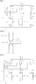
- Fig. 1 is a partial refrigerant cycle diagram of an air conditioner according to a first embodiment.
- the air conditioner of the current embodiment includes a plurality of compressors such as first, second, and third compressors 11, 12, and 13 that are disposed in parallel. Although three compressors are shown in Fig. 1 , the number of compressors can vary.
- the capacities of the compressors 11, 12, and 13 can be different. Furthermore, various types of compressors can be used for the compressors 11, 12, and 13. For example, an inverter compressor having a variable rotation speed or a constant speed compressor can be used.
- An inlet pipe unit is connected to the compressors 11, 12, and 13 to supply refrigerant from an evaporator (not shown) to the compressors 11, 12, and 13.
- the inlet pipe unit may include a common inlet pipe 30 and a plurality of branch inlet pipes 31, 32, and 33.
- the branch inlet pipes 31, 32, and 33 branch off from the common inlet pipe 30 and are connected to the respective compressors 11, 12, and 13.
- Refrigerant discharged from the evaporator is introduced into the common inlet pipe 30, is distributed to the branch inlet pipes 31, 32, and 33, and is then supplied to the compressors 11, 12, and 13.
- An outlet pipe unit is connected to the compressors 11, 12, and 13 for carrying the refrigerant discharged from the compressors 11, 12, and 13.
- the outlet pipe unit may include a plurality of branch outlet pipes 34, 35, and 36, and a common outlet pipe 37.
- the branch outlet pipes 34, 35, and 36 are connected to the respective compressors 11, 12, and 13.
- the branch outlet pipes 34, 35, and 36 are all connected to the common outlet pipe 37 where streams of refrigerant from the compressors 11, 12, and 13 combine.
- streams of refrigerant discharged from the compressors 11, 12, and 13 flow along the branch outlet pipes 34, 35, and 36, and then gather at the common outlet pipe 37. Thereafter, the gathered refrigerant flows to a condenser (not shown).
- Oil separators 21, 22, and 23 are disposed at the branch outlet pipes 34, 35, and 36 to separate oil from streams of refrigerant discharged from the compressors 11, 12, and 13.
- the branch outlet pipes 34, 35, and 36 include first pipes 34a, 35a, and 36a connected between the compressors 11, 12, and 13 and the Oil separators 21, 22, and 23.
- the branch outlet pipes 34, 35, and 36 further include second pipes 34b, 35b, and 36b connected between the common outlet pipe 37 and the oil separators 21, 22, and 23.
- An oil collection unit is connected to the oil separators 21, 22, and 23 to supply the oil separated by the oil separators 21, 22, and 23 back to the compressors 11, 12, and 13.
- the oil collection unit may include branch oil collection pipes 41, 42, and 43 and a common oil collection pipe 40.
- the branch oil collection pipes 41, 42, and 43 are connected to the oil separators 21, 22, and 23, respectively.
- the common oil collection pipe 40 is connected between the common inlet pipe 30 and the branch oil collection pipes 41, 42, and 43 for combining streams of oil coming from the branch oil collection pipes 41, 42, and 43 and supplying the combined oil to the common inlet pipe 30.
- Capillaries 44, 45, and 46 may be disposed at the respective branch oil collection pipes 41, 42, and 43 for reducing the pressure of oil flowing through the branch oil collection pipes 41, 42, and 43.
- first to third bypass pipes 51, 52, and 53 are connected to the compressors 11, 12, and 13 for discharging oil from the compressors 11, 12, and 13 when the compressors 11, 12, and 13 contain excessive oil.
- the other ends of the first to third bypass pipes 51, 52, and 53 are connected to the first pipes 34a, 35a, and 36a.
- the bypass pipes 51, 52, and 53 are usually connected to the compressors 11, 12, and 13 at heights higher than normal oil levels of the compressors 11, 12, and 13.
- the normal oil levels of the compressors 11, 12, and 13 may vary according to the capacities of the compressors 11, 12, and 13. Therefore, the bypass pipes 51, 52, and 53 may be connected to the compressors 11, 12, and 13 at different heights.
- Compressors can be low-pressure compressors or high-pressure compressors. In this embodiment, using high-pressure compressors for the compressors 11, 12, and 13 are desirable. Oil can be discharged from the compressors 11, 12, and 13 through the bypass pipes 51, 52, and 53 to outlets of the compressors 11, 12, and 13.
- the compressors 11, 12, and 13 are high-pressure type compressors
- the pressure of oil stored in the compressors 11, 12, and 13 can be high.
- the oil may be discharged from the compressors 11, 12, and 13 through the bypass pipes 51, 52, and 53.
- Fig. 2 is an enlarged view of portion A of Fig. 1 .
- pressure reduction parts 34c, 35c, and 36c are formed at the first pipes 34a, 35a, and 36a for reducing the pressure of the first pipes 34a, 35a, and 36a.
- the bypass pipes 51, 52, and 53 are connected to the pressure reduction parts 34c, 35c, and 36c.
- the pressure at the outlets of the compressors 11, 12, and 13 is approximately the same as the pressure inside the bypass pipes 51, 52, and 53. Therefore, the pressure reduction parts 34c, 35c, and 36c are formed at the first pipes 34a, 35a, and 36a to allow oil to smoothly flow from the bypass pipes 51, 52, and 53 to the first pipes 34a, 35a, and 36a.
- the pressure reduction parts 34c, 35c, and 36c may be formed by partially reducing the cross sectional areas of the first pipes 34a, 35a, and 36a. That is, the cross sectional areas of the pressure reduction parts 34c, 35c, and 36c are smaller than those of the first pipes 34a, 35a, and 36a.
- streams of the refrigerant increases in velocity at the pressure reduction parts 34c, 35c, and 36c but reduces in pressure at the pressure reduction parts 34c, 35c, and 36c.
- the pressures of the streams of the refrigerant become lower than the pressures of streams of oil of the bypass pipes 51, 52, and 53 so that the oil can smoothly flow from the bypass pipes 51, 52, and 53 to the first pipes 34a, 35a, and 36a.
- the pressure reduction parts 34c, 35c, and 36c are formed by partially reducing the cross sectional areas of the first pipes 34a, 35a, and 36a.
- other structures may be used for forming the pressure reduction parts 34c, 35c, and 36c.
- Fig. 3 is a partial refrigerant cycle diagram for illustrating an operation of the air conditioner depicted in Fig. 1 .
- the oil level of the first compressor 11 is normal, the oil level of the second compressor 12 is low, and the oil level of the third compressor 13 is high.
- refrigerant is introduced into the compressors 11, 12, and 13 for compression. Then, the refrigerant is discharged from the compressors 11, 12, and 13 to the branch outlet pipes 34, 35, and 36, and may include oil.
- the refrigerant is discharged from the first compressor 11 to the first bypass pipe 51 together with oil.
- the refrigerant and/or oil flow from the bypass pipes 51, 52, and 53 to the first pipes 34a, 35a, and 36a where they combine with the refrigerant and/or oil directly discharged from the compressors 11, 12, and 13 to the first pipes 34a, 35a, and 36a. Thereafter, the refrigerant and/or oil flow to the oil separators 21, 22, and 23.
- the oil level of the third compressor 13 decreases, and after the oil level of the third compressor 13 decreases to a level below the height at which the third bypass pipe 53 is connected to the third compressor 13, no more oil is discharged from the third compressor 13 to the third bypass pipe 53. In this case, only the compressed refrigerant is discharged from the third compressor 13 to the third bypass pipe 53.
- the oil separators 21, 22, and 23 separate the oil from the refrigerant.
- the separated oil is discharged from the oil separators 21, 22, and 23 to the branch oil collection pipes 41, 42, and 43.
- some oil not separated from the refrigerant at the oil separators 21, 22, and 23 may be discharged from the oil separators 21, 22, and 23 to the common outlet pipe 37 together with the refrigerant.
- the streams of oil While flowing along the branch oil collection pipes 41, 42, and 43, the streams of oil reduce in pressure and temperature at the capillaries 44, 45, and 46. Then, the streams of the oil gather at the common oil collection pipe 40. Thereafter, the oil flows to the common inlet pipe 30 where the oil is distributed to the branch inlet pipes 31, 32, and 33 together with refrigerant.
- the amounts of the refrigerant and the oil distributed from the common inlet pipe 30 to the branch inlet pipes 31, 32, and 33 are usually proportional to the capacities of the respective compressors 11, 12, and 13.
- the streams of oil flow along the branch oil collection pipes 41, 42, and 43, and are combined at the common oil collection pipe 40. Thereafter, the oil is distributed to the respective compressors 11, 12, and 13. Therefore, when one of the compressors 11, 12, and 13 is filled with insufficient oil (for example, the second compressor 12), the second compressor 12 may be supplied with oil from the other compressors. In this way, the oil levels of the compressors 11, 12, and 13 may be balanced.
- the oil separating rate of the oil separator 22 may be low compared with those of the other oil separators 21 and 23.
- oil separated by the other oil separators 21 and 23 may be supplied to the second compressor 12 from the common oil collection pipe 40 through the common inlet pipe 30 so that the oil level of the second compressor 12 may be properly maintained.
- Fig. 4 is a partial refrigerant cycle diagram of an air conditioner according to a second embodiment.
- the air conditioner of the second embodiment may have the same or similar structure as the air conditioner of the first embodiment except for oil and/or refrigerant discharging locations of the bypass pipes. In the following description of the second embodiment, only the difference will be explained, and the same or similar structure will not be described.
- first to third bypass pipes 61, 62, and 63 are connected to compressors 11, 12, and 13, and the other ends of the first to third bypass pipes 61, 62, and 63 are connected to second pipes 34b, 35b, and 36b that are connected between oil separators 21, 22, and 23 and a common outlet pipe 37.
- Pressure reduction parts are formed at the second pipes 34b, 35b, and 36b.
- oil discharged from the compressors 11, 12, and 13, and to the second pipes 34b, 35b, and 36b through the bypass pipes 61, 62, and 63 joins refrigerant discharged from the compressors 11, 12, and 13, and then the oil and/or refrigerant flows back to a common inlet pipe 30 through an condenser (not shown), an evaporator (not shown), and an expansion unit (not shown). Thereafter, the oil and/or refrigerant are distributed from the common inlet pipe 30 to the respective compressors 11, 12, and 13.
- bypass pipes 61, 62, and 63 are connected to the second pipes 34b, 35b, and 36b.
- the bypass pipes 61, 62, and 63 can be connected to the common outlet pipe 37.
- as many pressure reduction parts as the number of the bypass pipes 61, 62, and 63 may be formed at the common outlet pipe 37, or only one pressure reduction part may be formed at the common outlet pipe 37 and connected to the respective bypass pipes 61, 62, and 63.
- Fig. 5 is a partial refrigerant cycle diagram of an air conditioner according to a third embodiment.
- the air conditioner of the third embodiment may have the same or similar structure as the air conditioner of the second embodiment except for the structure of branch oil collection pipes. In the following description of the third embodiment, only the difference will be explained, and the same or similar structure will not be described.
- first to third branch oil collection pipes 71, 72, and 73 are connected to compressors 11, 12, and 13, and the other ends of the first to third branch oil collection pipes 71, 72, and 73 are connected to branch inlet pipes 31, 32, and 33. Therefore, oil separated at oil separators 21, 22, and 23 may be directed back to the original compressors 11, 12, and 13.
- Fig. 6 is a partial refrigerant cycle diagram of an air conditioner according to a fourth embodiment.
- the air conditioner of the fourth embodiment may have the same or similar structure as the air conditioner of the first embodiment except for the structure of an oil separator. In the following description of the fourth embodiment, only the difference will be explained, and the same or similar structure will not be described.
- only one oil separator 80 is disposed at a common outlet pipe 37 at which streams of refrigerant from branch outlet pipes 34, 35, and 36 are gathered. Ends of bypass pipes 91, 92, and 93 are connected to compressors 11, 12, and 13, and the other ends of the bypass pipes 91, 92, and 93 are connected to the branch outlet pipes 34, 35, and 36, respectively.
- An oil collection pipe 82 is connected between the oil separator 80 and a common inlet pipe 30 for allowing oil separated at the oil separator 80 to flow to the common inlet pipe 30.
- oil may be discharged from the compressors 11, 12, and 13 to the branch outlet pipes 34, 35, and 36 through the bypass pipes 91, 92, and 93, and streams of the oil may flow from the branch outlet pipes 34, 35, and 36 to the oil separator 80 through the common outlet pipe 37.
- the oil introduced into the oil separator 80 flows through the oil collection pipe 82 and is directed to the common inlet pipe 30. Thereafter, the oil is distributed back to the compressors 11, 12, and 13 from the common inlet pipe 30.
- oil may be separated by the oil separators, and streams of the separated oil may gather at the common oil collection pipe. Thereafter, the oil may be distributed to the respective compressors through the branch inlet pipes. Thus, the oil levels of the compressors may be properly maintained, and insufficient oil in the compressors may be prevented.
- the oil levels of the plurality of compressors of the air conditioner may be uniformly maintained, and thus the compressor having insufficient oil maybe prevented. Therefore, the air conditioner may be applied to various industrial fields.
- any reference in this specification to "one embodiment,” “an embodiment,” “exemplary embodiment,” etc. means that a particular feature, structure, or characteristic described in connection with the embodiment is included in at least one embodiment of the invention.
- the appearances of such phrases in various places in the specification are not necessarily all referring to the same embodiment.
Landscapes
- Engineering & Computer Science (AREA)
- Physics & Mathematics (AREA)
- Mechanical Engineering (AREA)
- Thermal Sciences (AREA)
- General Engineering & Computer Science (AREA)
- Chemical & Material Sciences (AREA)
- Analytical Chemistry (AREA)
- Power Engineering (AREA)
- Compressors, Vaccum Pumps And Other Relevant Systems (AREA)
- Compressor (AREA)
Claims (11)
- Climatiseur comprenant :une pluralité de compresseurs (11 à 13) ;une unité de tuyaux de sortie à travers laquelle de l'huile et/ou un fluide frigorigène évacués de la pluralité de compresseur (11 à 13) s'écoulent, l'unité de tuyaux de sortie comprenant une pluralité de tuyaux de sortie de dérivation (34 à 36) raccordés à la pluralité de compresseurs (11 à 13), et un tuyau de sortie commun (37) recevant des écoulements d'huile et/ou de fluide frigorigène en provenance de la pluralité de tuyaux de sortie de dérivation (34 à 36) ;au moins un séparateur d'huile (21 à 23 ; 80) séparant l'huile de l'huile et/ou du fluide frigorigène s'écoulant à travers l'unité de tuyaux de sortie ; etun collecteur d'huile (40 à 43 ; 71 à 73 ; 82) collectant l'huile séparée par le séparateur d'huile (21 à 23 ; 80) ;une unité de tuyaux d'entrée recevant l'huile et/ou le fluide frigorigène qui se sont écoulés à travers l'unité de tuyaux de sortie et permettant à l'huile et/ou au fluide frigorigène de s'écouler jusqu'à la pluralité de compresseurs (11 à 13), l'unité de tuyaux d'entrée recevant l'huile séparée par le séparateur d'huile (21 à 23 ; 80) ;une pluralité de tuyaux de contournement (51 à 53 ; 61 à 63 ; 91 à 93) raccordés à la pluralité de compresseurs (11 à 13) et permettant des écoulements de contournement de l'huile et/ou du fluide frigorigène depuis la pluralité de compresseurs (11 à 13) jusqu'à l'unité de tuyaux de sortie ; etune partie de réduction de pression (34c à 36c) disposée au niveau de la pluralité de tuyaux de sortie de dérivation (34 à 36) pour réduire une pression d'huile et/ou de fluide frigorigène évacués de la pluralité de compresseurs (11 à 13) ;caractérisé en ce que la partie de réduction de pression (34c à 36c) est formée en rétrécissant une portion de la pluralité de tuyaux de sortie de dérivation (34 à 36) pour réduire des aires en coupe transversale de la pluralité de tuyaux de sortie de dérivation (34 à 36), les écoulements de contournement de l'huile et/ou du fluide frigorigène des tuyaux de contournement (51 à 53 ; 61 à 63 ; 91 à 93) s'écoulent jusqu'à la partie de réduction de pression (34c à 36c), la pluralité de tuyaux de contournement (51 à 53 ; 61 à 63 ; 91 à 93) étant raccordés à la partie de réduction de pression (34c à 36c) respectivement ; etdans lequel la pluralité de tuyaux de contournement (51 à 53 ; 61 à 63 ; 91 à 93) sont raccordés à la pluralité de compresseurs (11 à 13) à des hauteurs plus élevées que des niveaux d'huile normaux de la pluralité de compresseurs (11 à 13).
- Climatiseur selon la revendication 1, dans lequel le tuyau de sortie commun (37) comprend autant de parties de réduction de pression (34c à 36c) que de tuyaux de contournement (51 à 53 ; 61 à 63), et les tuyaux de contournement (51 à 53 ; 61 à 63) sont raccordés aux parties de réduction de pression (34c à 36c), respectivement.
- Climatiseur selon la revendication 1, dans lequel le tuyau de sortie commun (37) comprend une seule partie de réduction de pression, et les tuyaux de contournement (91 à 93) sont généralement raccordés à la seule partie de réduction de pression.
- Climatiseur selon la revendication 1, dans lequel le climatiseur comprend une pluralité de séparateurs d'huile (21 à 23), et les séparateurs d'huile (21 à 23) sont disposés au niveau de tuyaux de sortie de dérivation (34 à 36) respectifs.
- Climatiseur selon la revendication 4, dans lequel le climatiseur comprend une pluralité de tuyaux de contournement (51 à 53 ; 61 à 63), et chaque tuyau de contournement (51 à 53 ; 61 à 63) est raccordé à une entrée ou une sortie du séparateur d'huile (21 à 23) respectif.
- Climatiseur selon la revendication 1, dans lequel le séparateur d'huile (80) est disposé au niveau du tuyau de sortie commun (37).
- Climatiseur selon la revendication 1, dans lequel l'unité de tuyaux d'entrée comprend :un tuyau d'entrée commun (30) à travers lequel le fluide frigorigène évacué d'un évaporateur s'écoule ; etdes tuyaux d'entrée de dérivation (31 à 33) montés en dérivation à partir du tuyau d'entrée commun (30) et raccordés respectivement aux compresseurs (11 à 13).
- Climatiseur selon la revendication 7, dans lequel le collecteur d'huile (40 à 43 ; 82) est raccordé au tuyau d'entrée commun (30).
- Climatiseur selon la revendication 8, dans lequel le climatiseur comprend autant de séparateurs d'huile (21 à 23) que de compresseurs (11 à 13), et le collecteur d'huile comprend des tuyaux de collecte d'huile de dérivation (41 à 43) raccordés respectivement aux séparateurs d'huile (21 à 23), et un tuyau de collecte d'huile commun (40) recevant des écoulements d'huile en provenance des tuyaux de collecte d'huile de dérivation (41 à 43) et raccordé au tuyau d'entrée commun (40).
- Climatiseur selon la revendication 7, dans lequel le climatiseur comprend autant de séparateurs d'huile (21 à 23) que de compresseurs (11 à 13) et autant de collecteurs d'huile (71 à 73) que de compresseurs (11 à 13), et les collecteurs d'huile (71 à 73) sont raccordés depuis les séparateurs d'huile (21 à 23) jusqu'aux tuyaux d'entrée de dérivation (31 à 33).
- Climatiseur selon la revendication 1, dans lequel le collecteur d'huile (40 à 43 ; 71 à 73 ; 82) comporte au moins un capillaire (44 à 46) pour réduire la pression d'huile lorsqu'elle s'écoule à travers le collecteur d'huile (40 à 43 ; 71 à 73 ; 82).
Applications Claiming Priority (2)
| Application Number | Priority Date | Filing Date | Title |
|---|---|---|---|
| KR1020070107561A KR101380036B1 (ko) | 2007-10-25 | 2007-10-25 | 공기 조화기 |
| PCT/KR2008/000417 WO2009054570A1 (fr) | 2007-10-25 | 2008-01-23 | Climatiseur |
Publications (3)
| Publication Number | Publication Date |
|---|---|
| EP2205909A1 EP2205909A1 (fr) | 2010-07-14 |
| EP2205909A4 EP2205909A4 (fr) | 2011-04-06 |
| EP2205909B1 true EP2205909B1 (fr) | 2017-05-17 |
Family
ID=40579662
Family Applications (1)
| Application Number | Title | Priority Date | Filing Date |
|---|---|---|---|
| EP08704926.8A Not-in-force EP2205909B1 (fr) | 2007-10-25 | 2008-01-23 | Climatiseur |
Country Status (6)
| Country | Link |
|---|---|
| US (1) | US8826691B2 (fr) |
| EP (1) | EP2205909B1 (fr) |
| KR (1) | KR101380036B1 (fr) |
| CN (1) | CN101836057B (fr) |
| ES (1) | ES2636899T3 (fr) |
| WO (1) | WO2009054570A1 (fr) |
Families Citing this family (10)
| Publication number | Priority date | Publication date | Assignee | Title |
|---|---|---|---|---|
| JP4407760B2 (ja) * | 2008-03-12 | 2010-02-03 | ダイキン工業株式会社 | 冷凍装置 |
| EP3051225B1 (fr) * | 2013-09-24 | 2021-05-19 | Mitsubishi Electric Corporation | Dispositif à cycle de réfrigération |
| JP6242235B2 (ja) * | 2014-02-20 | 2017-12-06 | 三菱電機株式会社 | 熱源ユニット及び冷凍サイクル装置 |
| WO2016098349A1 (fr) * | 2014-12-15 | 2016-06-23 | ダイキン工業株式会社 | Dispositif de congélation |
| EP3312526B1 (fr) * | 2015-06-16 | 2026-03-04 | Guangdong Meizhi Compressor Co., Ltd. | Dispositif à cycle de réfrigération |
| CN104990307B (zh) * | 2015-08-05 | 2017-11-17 | 珠海格力电器股份有限公司 | 空调器、压缩模块及压缩模块组 |
| US10969165B2 (en) | 2017-01-12 | 2021-04-06 | Emerson Climate Technologies, Inc. | Micro booster supermarket refrigeration architecture |
| EP3695175B1 (fr) | 2017-11-01 | 2023-05-17 | Siam Compressor Industry Co., Ltd. | Appareil à cycle frigorifique |
| WO2019137618A1 (fr) * | 2018-01-12 | 2019-07-18 | Carrier Corporation | Section de circuit de refroidissement et circuit de refroidissement |
| KR102751741B1 (ko) * | 2023-10-06 | 2025-01-10 | 한전케이피에스 주식회사 | 기액분리장치 |
Citations (2)
| Publication number | Priority date | Publication date | Assignee | Title |
|---|---|---|---|---|
| US3548612A (en) * | 1969-01-27 | 1970-12-22 | Tokyo Shibaura Electric Co | Refrigerating compressor with oil cooler |
| JPS5318042A (en) * | 1976-08-02 | 1978-02-18 | Hitachi Plant Eng & Constr Co Ltd | Oil collecting system in refrigeration cycle |
Family Cites Families (18)
| Publication number | Priority date | Publication date | Assignee | Title |
|---|---|---|---|---|
| US3238738A (en) * | 1964-02-12 | 1966-03-08 | Robert C Webber | Two-stage refrigeration system with by-pass means |
| JPS60245960A (ja) * | 1984-05-18 | 1985-12-05 | 三菱電機株式会社 | 空気調和機の冷凍サイクル |
| US4918942A (en) * | 1989-10-11 | 1990-04-24 | General Electric Company | Refrigeration system with dual evaporators and suction line heating |
| US5396779A (en) * | 1990-09-14 | 1995-03-14 | Nartron Corporation | Environmental control system |
| US5236311A (en) * | 1992-01-09 | 1993-08-17 | Tecumseh Products Company | Compressor device for controlling oil level in two-stage high dome compressor |
| TW212224B (fr) * | 1992-02-28 | 1993-09-01 | Sanyo Denki Kk | |
| ES2211908T3 (es) * | 1994-06-29 | 2004-07-16 | Daikin Industries, Ltd. | Refrigerador. |
| US5586450A (en) * | 1995-09-25 | 1996-12-24 | Carrier Corporation | Plural compressor oil level control |
| CN1188218A (zh) * | 1996-10-28 | 1998-07-22 | 松下冷机株式会社 | 用于多个压缩机的油位均衡系统 |
| JP3842855B2 (ja) | 1996-12-06 | 2006-11-08 | 三洋電機株式会社 | 空気調和機の室外ユニット |
| KR100407946B1 (ko) * | 2000-12-27 | 2003-12-01 | 엘지전자 주식회사 | 두 개의 압축기를 구비한 공기조화기 |
| JP4455546B2 (ja) * | 2001-03-13 | 2010-04-21 | 三菱電機株式会社 | 高圧シェルタイプ圧縮機及び冷凍装置 |
| JP3848098B2 (ja) * | 2001-05-01 | 2006-11-22 | 株式会社日立製作所 | 空気調和機 |
| CN1210534C (zh) * | 2003-12-26 | 2005-07-13 | 浙江大学 | 一种分体式热泵空调系统 |
| KR20060039344A (ko) * | 2004-11-02 | 2006-05-08 | 주식회사 대우일렉트로닉스 | 멀티에어컨에서 압축기의 압력 평형장치 |
| KR20060055154A (ko) * | 2004-11-18 | 2006-05-23 | 엘지전자 주식회사 | 멀티형 공기조화기의 압축기 오일 회수장치 |
| KR20060055830A (ko) * | 2004-11-19 | 2006-05-24 | 엘지전자 주식회사 | 압축기 오일 회수장치 |
| DK2147264T3 (en) * | 2007-04-24 | 2019-03-04 | Carrier Corp | Refrigerant vapor compression system |
-
2007
- 2007-10-25 KR KR1020070107561A patent/KR101380036B1/ko not_active Expired - Fee Related
-
2008
- 2008-01-23 WO PCT/KR2008/000417 patent/WO2009054570A1/fr not_active Ceased
- 2008-01-23 CN CN2008801132551A patent/CN101836057B/zh not_active Expired - Fee Related
- 2008-01-23 EP EP08704926.8A patent/EP2205909B1/fr not_active Not-in-force
- 2008-01-23 ES ES08704926.8T patent/ES2636899T3/es active Active
- 2008-01-30 US US12/010,874 patent/US8826691B2/en not_active Expired - Fee Related
Patent Citations (2)
| Publication number | Priority date | Publication date | Assignee | Title |
|---|---|---|---|---|
| US3548612A (en) * | 1969-01-27 | 1970-12-22 | Tokyo Shibaura Electric Co | Refrigerating compressor with oil cooler |
| JPS5318042A (en) * | 1976-08-02 | 1978-02-18 | Hitachi Plant Eng & Constr Co Ltd | Oil collecting system in refrigeration cycle |
Also Published As
| Publication number | Publication date |
|---|---|
| KR101380036B1 (ko) | 2014-04-01 |
| KR20090041849A (ko) | 2009-04-29 |
| EP2205909A4 (fr) | 2011-04-06 |
| US8826691B2 (en) | 2014-09-09 |
| US20090107169A1 (en) | 2009-04-30 |
| EP2205909A1 (fr) | 2010-07-14 |
| CN101836057B (zh) | 2012-08-29 |
| ES2636899T3 (es) | 2017-10-10 |
| CN101836057A (zh) | 2010-09-15 |
| WO2009054570A1 (fr) | 2009-04-30 |
Similar Documents
| Publication | Publication Date | Title |
|---|---|---|
| EP2205909B1 (fr) | Climatiseur | |
| US8375740B2 (en) | Air conditioner having plural compressors and plural oil separators | |
| JP4013261B2 (ja) | 冷凍装置 | |
| CN101668998A (zh) | 增强式制冷系统 | |
| EP2196747A1 (fr) | Appareil de réfrigération | |
| EP2538155B1 (fr) | Climatiseur | |
| JPH09126598A (ja) | 空気調和機の冷凍サイクルおよび冷凍サイクル部品 | |
| US7918106B2 (en) | Refrigeration system | |
| JPH07301465A (ja) | 二段圧縮式冷凍装置 | |
| JP4455546B2 (ja) | 高圧シェルタイプ圧縮機及び冷凍装置 | |
| CN100451498C (zh) | 复式空调以及用于控制该复式空调的方法 | |
| US20050066684A1 (en) | Compression mechanism of refrigerator | |
| CN103574957A (zh) | 多联机模块化系统 | |
| JPH0610562B2 (ja) | ヒートポンプ式冷暖房装置 | |
| JP2004301461A (ja) | 空気調和装置 | |
| CN216557747U (zh) | 压缩机组件、空调室外机和空调系统 | |
| WO2018212983A1 (fr) | Système de réfrigération et évaporateur à film tombant | |
| EP3572672A1 (fr) | Compresseur et système à cycle de réfrigération | |
| CN220083367U (zh) | 用于压缩机的回油系统、换热系统及空调器 | |
| CN104567129B (zh) | 空调系统 | |
| CN112747501B (zh) | 压缩机组件、热交换系统和电器设备 | |
| JPS60270A (ja) | 空気調和機 | |
| KR20030032432A (ko) | 냉동사이클의 압축기 균유장치 | |
| JP2005164056A (ja) | 冷凍空調装置 | |
| KR20080017717A (ko) | 공기조화장치 |
Legal Events
| Date | Code | Title | Description |
|---|---|---|---|
| PUAI | Public reference made under article 153(3) epc to a published international application that has entered the european phase |
Free format text: ORIGINAL CODE: 0009012 |
|
| 17P | Request for examination filed |
Effective date: 20100430 |
|
| AK | Designated contracting states |
Kind code of ref document: A1 Designated state(s): AT BE BG CH CY CZ DE DK EE ES FI FR GB GR HR HU IE IS IT LI LT LU LV MC MT NL NO PL PT RO SE SI SK TR |
|
| AX | Request for extension of the european patent |
Extension state: AL BA MK RS |
|
| DAX | Request for extension of the european patent (deleted) | ||
| A4 | Supplementary search report drawn up and despatched |
Effective date: 20110304 |
|
| 17Q | First examination report despatched |
Effective date: 20150212 |
|
| GRAP | Despatch of communication of intention to grant a patent |
Free format text: ORIGINAL CODE: EPIDOSNIGR1 |
|
| STAA | Information on the status of an ep patent application or granted ep patent |
Free format text: STATUS: GRANT OF PATENT IS INTENDED |
|
| INTG | Intention to grant announced |
Effective date: 20161215 |
|
| GRAS | Grant fee paid |
Free format text: ORIGINAL CODE: EPIDOSNIGR3 |
|
| GRAA | (expected) grant |
Free format text: ORIGINAL CODE: 0009210 |
|
| STAA | Information on the status of an ep patent application or granted ep patent |
Free format text: STATUS: THE PATENT HAS BEEN GRANTED |
|
| AK | Designated contracting states |
Kind code of ref document: B1 Designated state(s): AT BE BG CH CY CZ DE DK EE ES FI FR GB GR HR HU IE IS IT LI LT LU LV MC MT NL NO PL PT RO SE SI SK TR |
|
| REG | Reference to a national code |
Ref country code: GB Ref legal event code: FG4D |
|
| REG | Reference to a national code |
Ref country code: CH Ref legal event code: EP |
|
| REG | Reference to a national code |
Ref country code: IE Ref legal event code: FG4D |
|
| REG | Reference to a national code |
Ref country code: AT Ref legal event code: REF Ref document number: 894838 Country of ref document: AT Kind code of ref document: T Effective date: 20170615 |
|
| REG | Reference to a national code |
Ref country code: DE Ref legal event code: R096 Ref document number: 602008050306 Country of ref document: DE |
|
| REG | Reference to a national code |
Ref country code: NL Ref legal event code: MP Effective date: 20170517 |
|
| REG | Reference to a national code |
Ref country code: ES Ref legal event code: FG2A Ref document number: 2636899 Country of ref document: ES Kind code of ref document: T3 Effective date: 20171010 Ref country code: LT Ref legal event code: MG4D |
|
| REG | Reference to a national code |
Ref country code: AT Ref legal event code: MK05 Ref document number: 894838 Country of ref document: AT Kind code of ref document: T Effective date: 20170517 |
|
| PG25 | Lapsed in a contracting state [announced via postgrant information from national office to epo] |
Ref country code: GR Free format text: LAPSE BECAUSE OF FAILURE TO SUBMIT A TRANSLATION OF THE DESCRIPTION OR TO PAY THE FEE WITHIN THE PRESCRIBED TIME-LIMIT Effective date: 20170818 Ref country code: FI Free format text: LAPSE BECAUSE OF FAILURE TO SUBMIT A TRANSLATION OF THE DESCRIPTION OR TO PAY THE FEE WITHIN THE PRESCRIBED TIME-LIMIT Effective date: 20170517 Ref country code: NO Free format text: LAPSE BECAUSE OF FAILURE TO SUBMIT A TRANSLATION OF THE DESCRIPTION OR TO PAY THE FEE WITHIN THE PRESCRIBED TIME-LIMIT Effective date: 20170817 Ref country code: LT Free format text: LAPSE BECAUSE OF FAILURE TO SUBMIT A TRANSLATION OF THE DESCRIPTION OR TO PAY THE FEE WITHIN THE PRESCRIBED TIME-LIMIT Effective date: 20170517 Ref country code: HR Free format text: LAPSE BECAUSE OF FAILURE TO SUBMIT A TRANSLATION OF THE DESCRIPTION OR TO PAY THE FEE WITHIN THE PRESCRIBED TIME-LIMIT Effective date: 20170517 Ref country code: AT Free format text: LAPSE BECAUSE OF FAILURE TO SUBMIT A TRANSLATION OF THE DESCRIPTION OR TO PAY THE FEE WITHIN THE PRESCRIBED TIME-LIMIT Effective date: 20170517 |
|
| PG25 | Lapsed in a contracting state [announced via postgrant information from national office to epo] |
Ref country code: IS Free format text: LAPSE BECAUSE OF FAILURE TO SUBMIT A TRANSLATION OF THE DESCRIPTION OR TO PAY THE FEE WITHIN THE PRESCRIBED TIME-LIMIT Effective date: 20170917 Ref country code: LV Free format text: LAPSE BECAUSE OF FAILURE TO SUBMIT A TRANSLATION OF THE DESCRIPTION OR TO PAY THE FEE WITHIN THE PRESCRIBED TIME-LIMIT Effective date: 20170517 Ref country code: NL Free format text: LAPSE BECAUSE OF FAILURE TO SUBMIT A TRANSLATION OF THE DESCRIPTION OR TO PAY THE FEE WITHIN THE PRESCRIBED TIME-LIMIT Effective date: 20170517 Ref country code: PL Free format text: LAPSE BECAUSE OF FAILURE TO SUBMIT A TRANSLATION OF THE DESCRIPTION OR TO PAY THE FEE WITHIN THE PRESCRIBED TIME-LIMIT Effective date: 20170517 Ref country code: SE Free format text: LAPSE BECAUSE OF FAILURE TO SUBMIT A TRANSLATION OF THE DESCRIPTION OR TO PAY THE FEE WITHIN THE PRESCRIBED TIME-LIMIT Effective date: 20170517 Ref country code: BG Free format text: LAPSE BECAUSE OF FAILURE TO SUBMIT A TRANSLATION OF THE DESCRIPTION OR TO PAY THE FEE WITHIN THE PRESCRIBED TIME-LIMIT Effective date: 20170817 |
|
| REG | Reference to a national code |
Ref country code: FR Ref legal event code: PLFP Year of fee payment: 11 |
|
| PG25 | Lapsed in a contracting state [announced via postgrant information from national office to epo] |
Ref country code: RO Free format text: LAPSE BECAUSE OF FAILURE TO SUBMIT A TRANSLATION OF THE DESCRIPTION OR TO PAY THE FEE WITHIN THE PRESCRIBED TIME-LIMIT Effective date: 20170517 Ref country code: SK Free format text: LAPSE BECAUSE OF FAILURE TO SUBMIT A TRANSLATION OF THE DESCRIPTION OR TO PAY THE FEE WITHIN THE PRESCRIBED TIME-LIMIT Effective date: 20170517 Ref country code: EE Free format text: LAPSE BECAUSE OF FAILURE TO SUBMIT A TRANSLATION OF THE DESCRIPTION OR TO PAY THE FEE WITHIN THE PRESCRIBED TIME-LIMIT Effective date: 20170517 Ref country code: DK Free format text: LAPSE BECAUSE OF FAILURE TO SUBMIT A TRANSLATION OF THE DESCRIPTION OR TO PAY THE FEE WITHIN THE PRESCRIBED TIME-LIMIT Effective date: 20170517 Ref country code: CZ Free format text: LAPSE BECAUSE OF FAILURE TO SUBMIT A TRANSLATION OF THE DESCRIPTION OR TO PAY THE FEE WITHIN THE PRESCRIBED TIME-LIMIT Effective date: 20170517 |
|
| REG | Reference to a national code |
Ref country code: DE Ref legal event code: R097 Ref document number: 602008050306 Country of ref document: DE |
|
| PG25 | Lapsed in a contracting state [announced via postgrant information from national office to epo] |
Ref country code: IT Free format text: LAPSE BECAUSE OF FAILURE TO SUBMIT A TRANSLATION OF THE DESCRIPTION OR TO PAY THE FEE WITHIN THE PRESCRIBED TIME-LIMIT Effective date: 20170517 |
|
| PLBE | No opposition filed within time limit |
Free format text: ORIGINAL CODE: 0009261 |
|
| STAA | Information on the status of an ep patent application or granted ep patent |
Free format text: STATUS: NO OPPOSITION FILED WITHIN TIME LIMIT |
|
| 26N | No opposition filed |
Effective date: 20180220 |
|
| PG25 | Lapsed in a contracting state [announced via postgrant information from national office to epo] |
Ref country code: SI Free format text: LAPSE BECAUSE OF FAILURE TO SUBMIT A TRANSLATION OF THE DESCRIPTION OR TO PAY THE FEE WITHIN THE PRESCRIBED TIME-LIMIT Effective date: 20170517 |
|
| REG | Reference to a national code |
Ref country code: CH Ref legal event code: PL |
|
| GBPC | Gb: european patent ceased through non-payment of renewal fee |
Effective date: 20180123 |
|
| PG25 | Lapsed in a contracting state [announced via postgrant information from national office to epo] |
Ref country code: LU Free format text: LAPSE BECAUSE OF NON-PAYMENT OF DUE FEES Effective date: 20180123 |
|
| REG | Reference to a national code |
Ref country code: IE Ref legal event code: MM4A |
|
| REG | Reference to a national code |
Ref country code: BE Ref legal event code: MM Effective date: 20180131 |
|
| PG25 | Lapsed in a contracting state [announced via postgrant information from national office to epo] |
Ref country code: GB Free format text: LAPSE BECAUSE OF NON-PAYMENT OF DUE FEES Effective date: 20180123 Ref country code: CH Free format text: LAPSE BECAUSE OF NON-PAYMENT OF DUE FEES Effective date: 20180131 Ref country code: LI Free format text: LAPSE BECAUSE OF NON-PAYMENT OF DUE FEES Effective date: 20180131 Ref country code: BE Free format text: LAPSE BECAUSE OF NON-PAYMENT OF DUE FEES Effective date: 20180131 |
|
| PG25 | Lapsed in a contracting state [announced via postgrant information from national office to epo] |
Ref country code: IE Free format text: LAPSE BECAUSE OF NON-PAYMENT OF DUE FEES Effective date: 20180123 |
|
| PGFP | Annual fee paid to national office [announced via postgrant information from national office to epo] |
Ref country code: DE Payment date: 20190327 Year of fee payment: 16 |
|
| PG25 | Lapsed in a contracting state [announced via postgrant information from national office to epo] |
Ref country code: MC Free format text: LAPSE BECAUSE OF FAILURE TO SUBMIT A TRANSLATION OF THE DESCRIPTION OR TO PAY THE FEE WITHIN THE PRESCRIBED TIME-LIMIT Effective date: 20170517 |
|
| PG25 | Lapsed in a contracting state [announced via postgrant information from national office to epo] |
Ref country code: MT Free format text: LAPSE BECAUSE OF NON-PAYMENT OF DUE FEES Effective date: 20180123 |
|
| PGFP | Annual fee paid to national office [announced via postgrant information from national office to epo] |
Ref country code: FR Payment date: 20191209 Year of fee payment: 13 |
|
| PG25 | Lapsed in a contracting state [announced via postgrant information from national office to epo] |
Ref country code: TR Free format text: LAPSE BECAUSE OF FAILURE TO SUBMIT A TRANSLATION OF THE DESCRIPTION OR TO PAY THE FEE WITHIN THE PRESCRIBED TIME-LIMIT Effective date: 20170517 |
|
| PG25 | Lapsed in a contracting state [announced via postgrant information from national office to epo] |
Ref country code: PT Free format text: LAPSE BECAUSE OF FAILURE TO SUBMIT A TRANSLATION OF THE DESCRIPTION OR TO PAY THE FEE WITHIN THE PRESCRIBED TIME-LIMIT Effective date: 20170517 Ref country code: HU Free format text: LAPSE BECAUSE OF FAILURE TO SUBMIT A TRANSLATION OF THE DESCRIPTION OR TO PAY THE FEE WITHIN THE PRESCRIBED TIME-LIMIT; INVALID AB INITIO Effective date: 20080123 |
|
| PG25 | Lapsed in a contracting state [announced via postgrant information from national office to epo] |
Ref country code: CY Free format text: LAPSE BECAUSE OF FAILURE TO SUBMIT A TRANSLATION OF THE DESCRIPTION OR TO PAY THE FEE WITHIN THE PRESCRIBED TIME-LIMIT Effective date: 20170517 |
|
| REG | Reference to a national code |
Ref country code: ES Ref legal event code: FD2A Effective date: 20210607 |
|
| PG25 | Lapsed in a contracting state [announced via postgrant information from national office to epo] |
Ref country code: ES Free format text: LAPSE BECAUSE OF NON-PAYMENT OF DUE FEES Effective date: 20200124 |
|
| PG25 | Lapsed in a contracting state [announced via postgrant information from national office to epo] |
Ref country code: FR Free format text: LAPSE BECAUSE OF NON-PAYMENT OF DUE FEES Effective date: 20210131 |
|
| REG | Reference to a national code |
Ref country code: DE Ref legal event code: R119 Ref document number: 602008050306 Country of ref document: DE |
|
| PG25 | Lapsed in a contracting state [announced via postgrant information from national office to epo] |
Ref country code: DE Free format text: LAPSE BECAUSE OF NON-PAYMENT OF DUE FEES Effective date: 20230801 |