EP2206860A2 - Armature dotée d'un élément de verrouillage démontable - Google Patents
Armature dotée d'un élément de verrouillage démontable Download PDFInfo
- Publication number
- EP2206860A2 EP2206860A2 EP09179276A EP09179276A EP2206860A2 EP 2206860 A2 EP2206860 A2 EP 2206860A2 EP 09179276 A EP09179276 A EP 09179276A EP 09179276 A EP09179276 A EP 09179276A EP 2206860 A2 EP2206860 A2 EP 2206860A2
- Authority
- EP
- European Patent Office
- Prior art keywords
- locking element
- drive rod
- fitting
- faceplate
- fitting according
- Prior art date
- Legal status (The legal status is an assumption and is not a legal conclusion. Google has not performed a legal analysis and makes no representation as to the accuracy of the status listed.)
- Granted
Links
- 230000007704 transition Effects 0.000 description 3
- 238000006073 displacement reaction Methods 0.000 description 2
- 230000003993 interaction Effects 0.000 description 2
- 239000011324 bead Substances 0.000 description 1
- 238000005096 rolling process Methods 0.000 description 1
Images


Classifications
-
- E—FIXED CONSTRUCTIONS
- E05—LOCKS; KEYS; WINDOW OR DOOR FITTINGS; SAFES
- E05C—BOLTS OR FASTENING DEVICES FOR WINGS, SPECIALLY FOR DOORS OR WINDOWS
- E05C9/00—Arrangements of simultaneously actuated bolts or other securing devices at well-separated positions on the same wing
- E05C9/18—Details of fastening means or of fixed retaining means for the ends of bars
-
- E—FIXED CONSTRUCTIONS
- E05—LOCKS; KEYS; WINDOW OR DOOR FITTINGS; SAFES
- E05C—BOLTS OR FASTENING DEVICES FOR WINGS, SPECIALLY FOR DOORS OR WINDOWS
- E05C5/00—Fastening devices with bolts moving otherwise than only rectilinearly and only pivotally or rotatively
-
- E—FIXED CONSTRUCTIONS
- E05—LOCKS; KEYS; WINDOW OR DOOR FITTINGS; SAFES
- E05C—BOLTS OR FASTENING DEVICES FOR WINGS, SPECIALLY FOR DOORS OR WINDOWS
- E05C9/00—Arrangements of simultaneously actuated bolts or other securing devices at well-separated positions on the same wing
- E05C9/18—Details of fastening means or of fixed retaining means for the ends of bars
- E05C9/1825—Fastening means
- E05C9/1833—Fastening means performing sliding movements
- E05C9/1841—Fastening means performing sliding movements perpendicular to actuating bar
-
- E—FIXED CONSTRUCTIONS
- E05—LOCKS; KEYS; WINDOW OR DOOR FITTINGS; SAFES
- E05C—BOLTS OR FASTENING DEVICES FOR WINGS, SPECIALLY FOR DOORS OR WINDOWS
- E05C9/00—Arrangements of simultaneously actuated bolts or other securing devices at well-separated positions on the same wing
- E05C9/18—Details of fastening means or of fixed retaining means for the ends of bars
- E05C9/1825—Fastening means
- E05C9/1833—Fastening means performing sliding movements
- E05C9/185—Fastening means performing sliding movements parallel with actuating bar
Definitions
- the invention relates to a fitting, in particular for windows, doors or the like.
- a faceplate and a relative to the faceplate longitudinally displaceably arranged drive rod, wherein the faceplate has at least one passage opening for receiving a drivable via the drive rod locking element, and the drive rod at least between one Locking position in which the locking element is extended through the through hole of the face-plate and a release position in which the locking element is retracted in the direction of the face-plate, is movable.
- Such a fitting is for example from the DE 297 02 182 U1 known.
- a disadvantage of the known fitting is that the locking element is fixedly connected to the drive rod. This means that the drive rod not only has to be moved longitudinally relative to the faceplate, but also across it. It must therefore be provided a mechanism for the longitudinal displacement of the drive rod and another mechanism for the Querverschiebrete the drive rod.
- the object of the present invention is to provide a fitting with which the locking element can be extended and retracted in a simple manner.
- the locking element can be extended only for a locking position and optionally for a tilted position. If it is not needed for locking, it can be retracted into the fitting or a frame profile, so that it does not protrude on the rebate side or only insignificantly and thus does not hinder movement of a wing. As a result, a smaller clearance air can be provided between the wing and the fixed frame.
- a corresponding extension mechanism for the locking element is preferably provided, which cooperates with the drive rod.
- the longitudinal movement of the drive rod in the longitudinal direction of the fitting or in the fold circumferential direction
- the longitudinal movement of the drive rod is converted into a transverse movement of the locking element.
- the locking element is not fixedly connected to the drive rod. This does not mean that the locking element does not have to be connected to the drive rod at all.
- the locking element via levers or the like. Be connected to the drive rod, that a relative movement transverse to the direction of movement of the drive rod is possible.
- the space of the fitting can be reduced under certain circumstances, when the drive rod is movable only parallel to the faceplate. In addition, no devices must be provided which convert the longitudinal movement of the drive rod in a transverse movement of the drive rod.
- the locking element can be brought into a tilted position in which tilting opening of a wing is possible.
- the locking element can be extended or retracted depending on the design of the fitting in the tilted position.
- the passage opening of the faceplate has at least two sections of different width, wherein the narrower portion engages behind the locking element in a locking position in sections. This ensures that the locking element is held in a locking position and can not take the retracted release position.
- a bead which is wider than the narrower portion of the passage opening.
- bevels can be provided in the transition region of the sections of the passage opening or on the locking element.
- a defined position assumes the locking element in the locking position when lateral recesses are provided on the locking element, which receive in a locking position edges of the passage opening.
- the recesses can be stirred, for example, as lateral grooves that the Pick up the edges of the passage opening.
- the position of the locking element is clearly defined transversely to the direction of movement of the drive rod.
- the locking element is adjustable via an eccentric. By this measure, it is possible to adjust the contact pressure of the locking element in a locking position.
- the locking element may be provided on the drive rod at least one guide or control cam, by which the locking element is directly or indirectly guided or controlled.
- guide means or a transverse bolt (which can also be considered as a guide means of the locking element) may be provided on the locking element, which are guided in the guide or controlled by the control cam.
- the extension and retraction of the locking element as a function of the position of the drive rod can be realized.
- a longitudinal movement of the drive rod can be converted into a transverse movement of the locking element transversely to the direction of movement of the drive rod.
- the guide or control cam may be provided on a protruding perpendicularly from the drive rod tab or a bend of the drive rod.
- At least one stop limiting the movement of the locking element in the longitudinal direction of the fitting can be provided on the face-plate rail.
- the stop is from the faceplate.
- the limitation of the passage opening of the faceplate forms the stop.
- a toggle mechanism is provided for extending the adjusting element.
- the longitudinal movement of the drive rod can be translated differently in a movement of the locking element transversely to the movement of the drive rod.
- a lever may be provided which is pivotally mounted on the face-plate and guided on a guide of the drive rod, for example by means of a bolt.
- the locking element may have an opening into which a free end of the lever is retractable. This means that the lever does not have to be directly coupled or fastened to the locking element.
- the locking element can also be moved in the longitudinal direction of the fitting independently of the lever or the toggle mechanism.
- the locking element is pivotally mounted on the drive rod.
- the locking element can be connected via a bolt directly to the drive rod pivotally.
- the locking element is connected via a lever pivotally connected to the drive rod.
- the lever can be connected directly pivotally connected to the drive rod and the locking element can be pivotally connected to the lever.
- the lever is guided in a guide of the drive rod.
- This guide is preferably provided in a bend of the drive rod.
- the locking element is guided in a guide of the faceplate.
- the guide can be rectilinear or comprise a control curve or form such
- the locking position can be taken by the locking element particularly smoothly when the locking element is designed as a rolling pin.
- a spring element may be provided on the locking element, a spring element.
- the spring element can be supported on the faceplate and prevent tilting of the locking element in the locked position.
- the locking element may be movable in the extended state in the drive rod movement direction.
- the locking element can first be extended and then moved in drive rod longitudinal direction and thus brought into rear grip with a closing piece.
- the locking element is movable together with the drive rod in the drive rod movement direction.
- the drive rod and the locking element in the drive rod movement direction are movable relative to each other.
- the locking element in a guide element for. B. a sleeve can be arranged.
- a spring element for adjusting the contact pressure.
- FIG. 1 shows an exploded view of a fitting 10.
- Both the faceplate 11 and the drive rod 12 each have a passage opening 13, 14 through which a pin 15 of a locking member 16 can be inserted through.
- On the pin 15 a pin head 17 can be placed.
- the pin head 17 can be eccentrically adjusted on the pin 15 to adjust the contact pressure.
- a stop 27 is provided, which cooperates with the locking element 16.
- the passage opening 13 areas of different widths 28, 29.
- the wider area 29 allows the locking element 16 to perform a movement transversely to the direction of movement of the drive rod 11.
- the edges 30, 31 of the narrower portion 28 cooperate with grooves formed as lateral recesses 32 of the locking member 16 to fix this in a locking position.
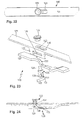
- FIG. 3a is a side view of the fitting 10 is shown.
- the locking element 16 is located in a retracted relative to the faceplate 11 release position.
- the guide means 20, 21 are located on the edge 22 of the tab 18.
- the tab 18 thus holds the locking member 16 in the retracted position.
- the wing on which the fitting 10 can be arranged assume a tilted position.
- FIG. 3b is a sectional view of the in the FIG. 3a shown situation shown. It can be clearly seen here that the locking element 16 abuts against the stop 27.
- the locking member 16 has been taken from the drive rod 12 to the position shown, wherein the drive rod 12 has performed a movement in the direction of arrow 33.
- the arrow direction 33 corresponds to a direction in the longitudinal direction of the fitting 10 or in the fold circumferential direction when the fitting 10 is mounted on a window or a door.
- the drive rod 12 has been moved in the direction of arrow 34, so that the run-on slope 35 (FIG. Fig. 3b ) on the tab 18 comes into contact with the guide element 20.
- the part 36 of the tab 18 is thus formed slightly higher than the edge 22 having part of the tab 18.
- the locking element 16 is located in the FIG. 4a still in a retracted position.
- the position of the fitting 10 shown here corresponds to a rotational position of the wing.
- the locking element 16 is retracted so that the wing on which the fitting 10 can be mounted can be freely rotated.
- FIG. 4a corresponding sectional view is in the FIG. 4b shown.
- the drive rod 11 is moved further in the direction of arrow 34, the guide elements 20, 21 enter into the guides 25, 26 and the locking element 16 is extended relative to the face-plate 11, which in the FIG. 5a is shown.
- the locking element 16 has been entrained in the direction of arrow 34, so that it comes into engagement with an abutment, such as a striker.
- the locking element 16 has been displaced relative to the faceplate 11.
- the locking element 16 has therefore carried out a superimposed movement in the direction of arrow 34 (direction of movement of the drive rod 12) and a movement transversely to the direction of movement of the drive rod 12.
- Fig. 5b is a sectional view showing the situation of FIG. 5a equivalent.
- the fitting 40 includes a faceplate 41 and a drive rod 42.
- the faceplate 41 has a through hole 43, which in turn has a wider portion 44 and a narrower portion 45. In the transition region between the portion 44 and the portion 45 ramp 46 are provided.
- the locking element 47 comprises a pin 48, which can pass through a passage opening 49 of the drive rod and the passage opening 43. On the pin 48, a pin head 17 can be placed. The pin head 17 can again be adjusted eccentrically.
- guide means 50, 51 are provided, which are guided in corresponding guides 52, the guide 52 is formed on a sleeve 53 of the drive rod 42.
- a lever 54 is pivotally mounted via a bolt 55 on the face plate 41. In this case, the bolt 55 is inserted through the opening 56 and the opening 57.
- the opening 56 is located on a tab 58 of the faceplate 41st
- tabs 59, 60 are provided which project perpendicularly from the drive rod 42.
- tabs 59, 60 are provided which project perpendicularly from the drive rod 42.
- guides 61, 62 are formed, in which a bolt 63 is guided, which is inserted through an opening 64 of the lever 54.
- the lever can be arranged between the tabs 59, 60.
- FIGS. 7a . 7b is the locking member 47 in a retracted, to the faceplate 41 pulled position.
- the free end 65 of the lever 54 is inserted through an opening 66 of the locking element 47 therethrough.
- the free end 65 extends virtually parallel to the longitudinal direction of the fitting 40.
- the drive rod 42 is located almost in a right end position.
- the bolt 63 is located in the section 67 of the guide 61.
- FIG. 11 shows an exploded view of a third embodiment of a fitting 80.
- the fitting 80 includes a faceplate 81 and a drive rod 82.
- a through hole 83 of the faceplate 81 and a through hole 84 of the drive rod 82 are penetrated by a pin 85 of the locking member 86.
- On the pin 85 a pin head 87 is placed.
- the passage opening 83 has a wider portion 88 at a narrower portion 89, wherein the edges of the portion 89 in recesses 90 on the locking member 86 can engage.
- the locking element 86 is disposed on a lever 91 which is pivotally mounted on the drive rod 82 via a pin 92.
- the bolt 92 is inserted through openings 93, 93 '.
- control cams 94, 95 are provided which cooperate with the lever 91.
- FIG. 12 The sectional view of FIG. 12 can be seen that the locking element 86 via the lever 91 pivotally mounted on the drive rod 82nd is arranged. In the in the FIG. 12 shown position, the locking element 86 is extended. The end 96 of the lever 91 is located on the control cam 95. The portion 89 of the through hole 83 engages in the recess 90 and thereby also holds the locking member 86 in the locked position shown.
- FIG. 13 is one of the FIG. 12 corresponding side view of the fitting 80 is shown.
- the drive rod 82 was displaced in the direction of arrow 97.
- the end 98 of the lever 91 comes into contact with the control cam 94.
- the lever 91 is pivoted, so that a movement of the locking element 86 obliquely to the direction of movement of the drive rod 82 results.
- the locking element 86 is located in the FIG. 15 in a retracted position. In this case, the locking element 86 can be completely or else only partially retracted.
- FIG. 16 a plan view of the fitting 80 is shown.
- the wide section 88 is also followed by a section 99, which is also narrower.
- the locking element 86 in the in the FIG. 15 be shown shifted position.
- FIG. 17 shows a fourth embodiment of a fitting 100 in an exploded view.
- a drive rod 102 Below a faceplate 101 is a drive rod 102.
- the faceplate 101 has a through hole 103 with a wider portion 104 and a narrower portion 105.
- a spigot 106 of a locking element 107 extends through the opening 103.
- a pin head 108 On the pin 106, a pin head 108 is attached.
- On the drive rod 102 On the drive rod 102, a bend 109 is provided, on which a guide 110 is formed.
- a lever 111 is guided via a bolt 112 in the guide 110 and also pivotable relative to the drive rod 102.
- the other end of the lever 111 is connected via a bolt 113 with the opening 114 of the locking element 107.
- the lever 111 is thus pivotable with respect to the locking element 107.
- the locking element 107 is connected via the lever 111, so indirectly, pivotally connected to the drive rod 102
- FIG. 18 is a sectional view of the fitting 100 is shown.
- the corresponding side view is in the FIG. 19 shown.
- the locking element 107 is located in the section 105 of the faceplate 101.
- the drive rod 102 is in a right end position.
- the edges of the portion 105 engage in the recess 115 of the locking element 107 and hold it in the locked position.
- the locking member 107 is reliably brought from the drive rod 102 in the wider portions 104 of the through hole 103.
- By downward movement of the locking member 107 performs the rotatably connected to the lever 111 bolt 112 rotates and releases the guide 110 so that the drive rod 102 relative to the bolt 112, lever 111 and locking member 107 can be moved.
- Locking element 107 and drive rod 102 are therefore decoupled.
- the guide 110 has a widening, in which the (eccentric) bolt is held in a form-fitting manner with the locking element 107 extended.
- the FIG. 20 shows a situation shortly before the locking member 107 is extended.
- the locking element 107 is located in the section 104 of the passage opening 103. It can not be moved into the section 105 in the retracted position. A movement of the drive rod 102 in the direction of arrow 116 therefore causes an extension of the locking element 107. Subsequently, when it is extended, it can in the in the FIG. 19 shown position in which it is taken by the drive rod 102 in the direction of arrow 116.
- the bolt 113 ie the pivot point of the lever 111 with the locking element 107 is arranged somewhat Stulpschienenmillr than the bolt 112, so the pivot point of the lever 111 with the drive rod 102,
- FIG. 21 shows a position in which the drive rod 102 assumes a left end position, in this end position, the locking member 107 is reliably held in the retracted position, for. B. is prevented via positive engagement between the bolt 112 and guide 110 a rotational movement. The bolt 112 is moved in the guide 110 to the right.
- FIG. 22 shows a plan view of the fitting 100.
- the locking element 107 is in a retracted position, not in the section 105th
- the FIG. 23 shows an exploded view of a fifth embodiment of a fitting 120.
- the fitting 120 includes a faceplate 121 and a drive rod 122.
- the faceplate 121 has a through hole 123. This is penetrated by a pin 124 of a locking element 125. On the pin 124 a pin head 126 is arranged.
- On the face plate 121 tabs 127 are provided with a guide 128.
- the locking element 125 is guided via a bolt 129 in the guide 128.
- the bolt 129 passes through through holes 130, 131 of the locking element.
- the drive rod 122 has a control cam 132. In the area of the control cam 132, the drive rod 122 is narrower than in the other areas.
- the locking element 125 can be placed with its slot 133 on the control cam 132.
- the pin 129 is arranged below the control cam 132. From this as well as from the other embodiments it is clear that the locking element can be formed from a locking element body and a locking element head.
- FIG. 24 shows a sectional view through the fitting 120.
- the locking element 125 has a guide means 134 which slides along the control cam 132.
- the bolt 129 engages under the drive rod section which has the control cam 132.
- the in the FIG. 24 shown position is in a side view in the FIG. 25 shown again.
- the locking element 125 is in an extended position.
- the locking member 125 is taken by the drive rod 122 and moved along the guide 128, so that the locking member 125 is engaged behind by the narrow portion 136 of the through hole 123.
- This position is in the FIG. 26 shown in a side view.
- FIG. 28 a plan view of the fitting 120 is shown.
- FIGS. 29-32 show a similar fitting 140, as in the Figures 1 - 5b was shown. Therefore, the same reference numerals are used. The main difference is that only one guide 26 is provided on the tab 18. Accordingly, the locking element 16 only has a guide means 20,
- the fitting 150 includes a faceplate 151 and a drive rod 152.
- the faceplate 151 has a through hole 153 which centrally to a widened portion 154 and two subsequent narrow portions 156, 157 has.
- the passage opening 153 is penetrated by a pin 158 of a locking element 159, wherein on the pin 158 a pin head 160 can be attached.
- tabs 161 are provided with guides 162, 163. With the guides 162, 163, a guide means 164 of the locking element 159 cooperates.
- a spring element 165 is provided, which is connected to the locking element 159, and via which the locking element 159 can be supported on the face-plate 151.
- FIG. 34 The sectional view of FIG. 34
- the locking element 159 is in an extended position relative to the faceplate 151.
- the guide means 164 was moved obliquely upward in the guide 163.
- the locking element 159 is supported on the face plate 151 via the spring element 165.
- the locking element is located 159 in the wider portion 155. Only in the extended state, the locking element 159 is moved inmaschinestangellindsraum.
- FIG. 35 a retracted position of the locking element 159 can be seen. If the drive rod 152 is moved further in the direction of arrow 168, as shown in the FIG. 36 As can be seen, the guide means 164 in the guide 162 is moved obliquely upwards. The locking element 159 is again in an extended position. However, this position corresponds to a tilted position of the wing. This means that in this position of the fitting 150, a wing on which the fitting 150 is mounted, can be tilted.
- FIG. 37 a plan view of the fitting 150 is shown.
- the locking element 159 is in a locking position, as in the FIG. 34 is shown.
- the fittings 140, 150 can be combined on a single espagnolette fitting.
- Rotary opening of a wing is possible when the locking elements 16, 159 in the Figures 31 . 35 occupy shown positions.
- Tipping open a wing is possible when in the Figures 32 . 36 shown positions are taken.
- the drive rods 12, 152 may be motion coupled to one another or constitute a single drive rod.
- the fitting 180 also comprises a faceplate 181 and a drive rod 182.
- the faceplate 181 has a through-opening 183, which has a wider portion 184 and two narrower portions 185, 186 adjoining thereto.
- the locking element 187 comprises a pin 188, which can pass through a passage opening 189 of the drive rod 182 and the passage opening 183 of the faceplate 181.
- a pin head 190th be put on.
- the pin head 190 can in turn be adjusted eccentrically.
- guide means 191, 192 are provided, which are guided in the corresponding guides 193.
- the guide 193 is formed on a sleeve 194 of the drive rod 182.
- Attached to the faceplate 181 is a stirrup-like element 195 having two circumferentially oriented portions 196, 197 aligned parallel to the faceplate 181 and having two tapered portions 198, 199 tapered to a point.
- the bracket 195 extends through the pin 188th
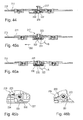
- the locking element 187 is in an extended position. It can be seen that the portion 197 of the bracket 195 extends through the lower part of the pin 188 and thus holds this in the raised position. If now the drive rod 182 is moved in the direction of the arrow 200, the locking element 187 reaches in the region of the inclined portion 199 of the bracket 195. This situation is in the FIG. 40 shown.
- the locking member 187 slides along the inclined portion 199 down so that it occupies a retracted, so drawn to the faceplate 181 position. It can be seen that the pin 188 has bevels 201, 202, which are adapted to the pitch of the sections 198, 199. The pin 188 is now in the area 184 of the through hole 183 of the face plate 181. Upon further movement of the drive rod 182 in the direction of arrow 200, the locking member 187 is brought by cooperation of the slope 202 and the portion 198 back to an extended position, as shown in the Figure 42 is shown. The locking element 187 is now located in the region 185 of the through hole 183 of the faceplate 181. The edges of the portion 185 engage in grooves 203 of the pin 188 and thereby hold it in the extended position. In the Figure 42 shown position, the pin 188 in the region of the portion 196 of the bracket 195th
- the fitting 210 comprises a faceplate 211 and a drive rod 212.
- the faceplate 211 has a through-opening 213, which has a wider portion 214 and two adjoining narrower portions 215, 216. In the transition region between the sections 214, 215 and 214, 216 bevels are provided.
- the locking element 217 comprises a pin 218, which can pass through a passage opening 219 of the drive rod 212 and the passage opening 213 of the faceplate 211.
- a pin head 219 can be placed on the pin 218, a pin head 219 can be placed.
- the pin head 250 can in turn be adjusted eccentrically.
- guide means 220 On the locking element 217 guide means 220 are provided, which are guided in corresponding guides 221 of the drive rod 212.
- Two levers 222, 223 are pivotally mounted by bolts 224, 225 on downwardly projecting tabs 226 of the drive rod 212.
- the levers 222, 223 engage the pin 218 and also cooperate with a U-shaped bearing part 227, which can be fastened by inserting it on the face-plate rail 211.
- the operation of the ninth embodiment of the fitting 210 results from the following figures.
- the sectional view according to FIG. 44 it can be seen that the locking element 217 is in an extended position.
- the levers 222, 223 are pivoted upwards.
- the pin 218 is located with its recess 228 in the region of the portion 216, so that the edges of the portion 216 of the faceplate 211, engage in the recesses 228 and thereby hold the locking member 217 in the extended position.
Landscapes
- Engineering & Computer Science (AREA)
- Mechanical Engineering (AREA)
- Lock And Its Accessories (AREA)
- Support Devices For Sliding Doors (AREA)
- Power-Operated Mechanisms For Wings (AREA)
- Steering Controls (AREA)
Priority Applications (1)
| Application Number | Priority Date | Filing Date | Title |
|---|---|---|---|
| PL09179276T PL2206860T3 (pl) | 2008-12-23 | 2009-12-15 | Okucie z wysuwnym elementem ryglującym |
Applications Claiming Priority (1)
| Application Number | Priority Date | Filing Date | Title |
|---|---|---|---|
| DE102008062950A DE102008062950A1 (de) | 2008-12-23 | 2008-12-23 | Beschlag mit ausfahrbarem Verriegelungselement |
Publications (3)
| Publication Number | Publication Date |
|---|---|
| EP2206860A2 true EP2206860A2 (fr) | 2010-07-14 |
| EP2206860A3 EP2206860A3 (fr) | 2011-09-14 |
| EP2206860B1 EP2206860B1 (fr) | 2012-12-05 |
Family
ID=41819253
Family Applications (1)
| Application Number | Title | Priority Date | Filing Date |
|---|---|---|---|
| EP09179276A Active EP2206860B1 (fr) | 2008-12-23 | 2009-12-15 | Armature dotée d'un élément de verrouillage extensible |
Country Status (3)
| Country | Link |
|---|---|
| EP (1) | EP2206860B1 (fr) |
| DE (1) | DE102008062950A1 (fr) |
| PL (1) | PL2206860T3 (fr) |
Cited By (5)
| Publication number | Priority date | Publication date | Assignee | Title |
|---|---|---|---|---|
| GB2486473A (en) * | 2010-12-16 | 2012-06-20 | Window Fab & Fixing Supplies | Locking Mechanism |
| EP2418346A3 (fr) * | 2010-08-14 | 2013-11-13 | HAUTAU GmbH | Procédé et dispositif de mise en sécurité d'un vantail coulissant et levable sur la feuillure supérieure |
| WO2016062595A1 (fr) * | 2014-10-23 | 2016-04-28 | Maco Technologie Gmbh | Ensemble ferrure |
| GB2553408A (en) * | 2016-06-16 | 2018-03-07 | Spire Mfg Limited | Locking mechanism |
| WO2019050763A1 (fr) * | 2017-09-05 | 2019-03-14 | Philip Morris Usa Inc. | Système et procédé de retenue de grille de récipient |
Families Citing this family (2)
| Publication number | Priority date | Publication date | Assignee | Title |
|---|---|---|---|---|
| DE102024114865A1 (de) * | 2024-05-27 | 2025-11-27 | Gretsch-Unitas GmbH Baubeschläge | Verriegelungsbeschlag und Tür- oder Fensteranordnung |
| DE102024126385A1 (de) * | 2024-09-13 | 2026-03-19 | Aug. Winkhaus SE | Beschlag für einen gegen einen Rahmen schwenkbaren Flügel |
Citations (4)
| Publication number | Priority date | Publication date | Assignee | Title |
|---|---|---|---|---|
| DE7326141U (de) | 1973-07-17 | 1973-11-08 | Schaumburg-Lippische Baubeschlagfab W Hautau Gmbh | Treibstangenverschluss fuer fluegel von fenstern, tueren oder dgl |
| DE29702182U1 (de) | 1997-01-29 | 1997-03-27 | Mayer & Co., Salzburg | Beschlag, insbesondere für Fenster oder Türen |
| DE10202088A1 (de) | 2001-01-19 | 2002-07-25 | Msl Schloss Und Beschlaegefabr | Schloss |
| EP1293627A2 (fr) | 2001-09-18 | 2003-03-19 | Aug. Winkhaus GmbH & Co. KG | Crémone |
-
2008
- 2008-12-23 DE DE102008062950A patent/DE102008062950A1/de not_active Withdrawn
-
2009
- 2009-12-15 EP EP09179276A patent/EP2206860B1/fr active Active
- 2009-12-15 PL PL09179276T patent/PL2206860T3/pl unknown
Patent Citations (4)
| Publication number | Priority date | Publication date | Assignee | Title |
|---|---|---|---|---|
| DE7326141U (de) | 1973-07-17 | 1973-11-08 | Schaumburg-Lippische Baubeschlagfab W Hautau Gmbh | Treibstangenverschluss fuer fluegel von fenstern, tueren oder dgl |
| DE29702182U1 (de) | 1997-01-29 | 1997-03-27 | Mayer & Co., Salzburg | Beschlag, insbesondere für Fenster oder Türen |
| DE10202088A1 (de) | 2001-01-19 | 2002-07-25 | Msl Schloss Und Beschlaegefabr | Schloss |
| EP1293627A2 (fr) | 2001-09-18 | 2003-03-19 | Aug. Winkhaus GmbH & Co. KG | Crémone |
Cited By (12)
| Publication number | Priority date | Publication date | Assignee | Title |
|---|---|---|---|---|
| EP2418346A3 (fr) * | 2010-08-14 | 2013-11-13 | HAUTAU GmbH | Procédé et dispositif de mise en sécurité d'un vantail coulissant et levable sur la feuillure supérieure |
| GB2486473A (en) * | 2010-12-16 | 2012-06-20 | Window Fab & Fixing Supplies | Locking Mechanism |
| GB2486473B (en) * | 2010-12-16 | 2016-06-22 | Window Fabrication & Fixing Supplies Ltd | Slider Arm Cam Locking Arrangment |
| WO2016062595A1 (fr) * | 2014-10-23 | 2016-04-28 | Maco Technologie Gmbh | Ensemble ferrure |
| GB2553408A (en) * | 2016-06-16 | 2018-03-07 | Spire Mfg Limited | Locking mechanism |
| GB2553408B (en) * | 2016-06-16 | 2021-06-16 | Spire Mfg Limited | Locking mechanism |
| WO2019050763A1 (fr) * | 2017-09-05 | 2019-03-14 | Philip Morris Usa Inc. | Système et procédé de retenue de grille de récipient |
| US11284642B2 (en) | 2017-09-05 | 2022-03-29 | Philip Morris Usa Inc. | Vessel screen retaining system and method |
| US20220167657A1 (en) * | 2017-09-05 | 2022-06-02 | Philip Morris Usa Inc. | Vessel screen retaining system and method |
| US11918030B2 (en) | 2017-09-05 | 2024-03-05 | Philip Morris Usa Inc. | Vessel screen retaining system and method |
| US20240196951A1 (en) * | 2017-09-05 | 2024-06-20 | Philip Morris Usa Inc. | Vessel screen retaining system and method |
| US12290094B2 (en) | 2017-09-05 | 2025-05-06 | Philip Morris Usa Inc. | Vessel screen retaining system and method |
Also Published As
| Publication number | Publication date |
|---|---|
| DE102008062950A1 (de) | 2010-06-24 |
| EP2206860B1 (fr) | 2012-12-05 |
| PL2206860T3 (pl) | 2013-05-31 |
| EP2206860A3 (fr) | 2011-09-14 |
Similar Documents
| Publication | Publication Date | Title |
|---|---|---|
| EP2206860B1 (fr) | Armature dotée d'un élément de verrouillage extensible | |
| EP1582673B1 (fr) | Gâche pour fenêtre ou porte-fenêtres | |
| EP3795783B1 (fr) | Fermeture secondaire pour un verrouillage à points multiples | |
| EP2165868B1 (fr) | Système de porte coulissante pivotante | |
| EP3045624A1 (fr) | Dispositif de verrouillage d'un battant pivotant | |
| EP1008713B1 (fr) | Dispositif de verrouillage | |
| EP2143860B1 (fr) | Dispositif de fermeture pour fenêtres ou portes | |
| DE29601966U1 (de) | Zusatzschloß für Flügel von Türen, Fenstern o.dgl. | |
| EP1264954B1 (fr) | Système de verouillage | |
| EP2143859A2 (fr) | Système de verouillage | |
| DE10031820A1 (de) | Ausstellvorrichtung für einen an einem Rahmen schwenkbar angebrachten Kipp- oder Dreh-Kipp-Flügel | |
| EP3299556A1 (fr) | Dispositif de verrouillage de battant installé de manière oscillante | |
| EP0972900B1 (fr) | Crémone-serrure | |
| DE19846048A1 (de) | Spaltlüftungsvorrichtung | |
| EP2453086B1 (fr) | Ferrure de crémone pour battant fixe de fenêtres ou de portes à deux vantaux sans montant médian | |
| DE19856451C2 (de) | Verriegelungsvorrichtung | |
| DE1964842A1 (de) | Beschlag fuer Fenster,Tueren u.dgl. | |
| DE102006002830B4 (de) | Ausstellvorrichtung für den Flügel eines Fensters oder dergleichen | |
| DE202008008232U1 (de) | Treibstangenschloss | |
| EP4146888A1 (fr) | Ensemble charnière à actionnement commun | |
| DE102016004915B3 (de) | Beschlag für ein Fenster, Verfahren zum Herstellen des Beschlags sowie entsprechendes Fenster | |
| EP2626492A2 (fr) | Ferrure à crémone avec un mode d'entrebaillement- et un mode de fermeture et une méthode | |
| EP2685040B1 (fr) | Composant précontraint et procédé de fonctionnement pour une fenêtre ou une porte-fenêtre | |
| DE10162194B4 (de) | Riegelwerksteuerung | |
| EP2690241B1 (fr) | Armature pour une porte coulissante à fermeture parallèle ou une fenêtre coulissante à fermeture parallèle |
Legal Events
| Date | Code | Title | Description |
|---|---|---|---|
| PUAI | Public reference made under article 153(3) epc to a published international application that has entered the european phase |
Free format text: ORIGINAL CODE: 0009012 |
|
| AK | Designated contracting states |
Kind code of ref document: A2 Designated state(s): AT BE BG CH CY CZ DE DK EE ES FI FR GB GR HR HU IE IS IT LI LT LU LV MC MK MT NL NO PL PT RO SE SI SK SM TR |
|
| AX | Request for extension of the european patent |
Extension state: AL BA RS |
|
| PUAL | Search report despatched |
Free format text: ORIGINAL CODE: 0009013 |
|
| AK | Designated contracting states |
Kind code of ref document: A3 Designated state(s): AT BE BG CH CY CZ DE DK EE ES FI FR GB GR HR HU IE IS IT LI LT LU LV MC MK MT NL NO PL PT RO SE SI SK SM TR |
|
| AX | Request for extension of the european patent |
Extension state: AL BA RS |
|
| RIC1 | Information provided on ipc code assigned before grant |
Ipc: E05C 9/00 20060101AFI20110805BHEP |
|
| 17P | Request for examination filed |
Effective date: 20120217 |
|
| REG | Reference to a national code |
Ref country code: DE Ref legal event code: R079 Ref document number: 502009005567 Country of ref document: DE Free format text: PREVIOUS MAIN CLASS: E05C0009000000 Ipc: E05C0009180000 |
|
| GRAP | Despatch of communication of intention to grant a patent |
Free format text: ORIGINAL CODE: EPIDOSNIGR1 |
|
| RIC1 | Information provided on ipc code assigned before grant |
Ipc: E05C 9/18 20060101AFI20120626BHEP |
|
| GRAS | Grant fee paid |
Free format text: ORIGINAL CODE: EPIDOSNIGR3 |
|
| GRAA | (expected) grant |
Free format text: ORIGINAL CODE: 0009210 |
|
| AK | Designated contracting states |
Kind code of ref document: B1 Designated state(s): AT BE BG CH CY CZ DE DK EE ES FI FR GB GR HR HU IE IS IT LI LT LU LV MC MK MT NL NO PL PT RO SE SI SK SM TR |
|
| REG | Reference to a national code |
Ref country code: GB Ref legal event code: FG4D Free format text: NOT ENGLISH |
|
| REG | Reference to a national code |
Ref country code: CH Ref legal event code: EP |
|
| REG | Reference to a national code |
Ref country code: AT Ref legal event code: REF Ref document number: 587394 Country of ref document: AT Kind code of ref document: T Effective date: 20121215 |
|
| REG | Reference to a national code |
Ref country code: IE Ref legal event code: FG4D Free format text: LANGUAGE OF EP DOCUMENT: GERMAN |
|
| REG | Reference to a national code |
Ref country code: DE Ref legal event code: R096 Ref document number: 502009005567 Country of ref document: DE Effective date: 20130131 |
|
| PG25 | Lapsed in a contracting state [announced via postgrant information from national office to epo] |
Ref country code: NO Free format text: LAPSE BECAUSE OF FAILURE TO SUBMIT A TRANSLATION OF THE DESCRIPTION OR TO PAY THE FEE WITHIN THE PRESCRIBED TIME-LIMIT Effective date: 20130305 Ref country code: SE Free format text: LAPSE BECAUSE OF FAILURE TO SUBMIT A TRANSLATION OF THE DESCRIPTION OR TO PAY THE FEE WITHIN THE PRESCRIBED TIME-LIMIT Effective date: 20121205 Ref country code: LT Free format text: LAPSE BECAUSE OF FAILURE TO SUBMIT A TRANSLATION OF THE DESCRIPTION OR TO PAY THE FEE WITHIN THE PRESCRIBED TIME-LIMIT Effective date: 20121205 Ref country code: ES Free format text: LAPSE BECAUSE OF FAILURE TO SUBMIT A TRANSLATION OF THE DESCRIPTION OR TO PAY THE FEE WITHIN THE PRESCRIBED TIME-LIMIT Effective date: 20130316 Ref country code: FI Free format text: LAPSE BECAUSE OF FAILURE TO SUBMIT A TRANSLATION OF THE DESCRIPTION OR TO PAY THE FEE WITHIN THE PRESCRIBED TIME-LIMIT Effective date: 20121205 |
|
| REG | Reference to a national code |
Ref country code: NL Ref legal event code: VDEP Effective date: 20121205 |
|
| REG | Reference to a national code |
Ref country code: LT Ref legal event code: MG4D |
|
| PG25 | Lapsed in a contracting state [announced via postgrant information from national office to epo] |
Ref country code: LV Free format text: LAPSE BECAUSE OF FAILURE TO SUBMIT A TRANSLATION OF THE DESCRIPTION OR TO PAY THE FEE WITHIN THE PRESCRIBED TIME-LIMIT Effective date: 20121205 Ref country code: GR Free format text: LAPSE BECAUSE OF FAILURE TO SUBMIT A TRANSLATION OF THE DESCRIPTION OR TO PAY THE FEE WITHIN THE PRESCRIBED TIME-LIMIT Effective date: 20130306 Ref country code: SI Free format text: LAPSE BECAUSE OF FAILURE TO SUBMIT A TRANSLATION OF THE DESCRIPTION OR TO PAY THE FEE WITHIN THE PRESCRIBED TIME-LIMIT Effective date: 20121205 |
|
| REG | Reference to a national code |
Ref country code: PL Ref legal event code: T3 |
|
| BERE | Be: lapsed |
Owner name: ROTO FRANK A.G. Effective date: 20121231 |
|
| PG25 | Lapsed in a contracting state [announced via postgrant information from national office to epo] |
Ref country code: MC Free format text: LAPSE BECAUSE OF NON-PAYMENT OF DUE FEES Effective date: 20121231 Ref country code: IS Free format text: LAPSE BECAUSE OF FAILURE TO SUBMIT A TRANSLATION OF THE DESCRIPTION OR TO PAY THE FEE WITHIN THE PRESCRIBED TIME-LIMIT Effective date: 20130405 Ref country code: CZ Free format text: LAPSE BECAUSE OF FAILURE TO SUBMIT A TRANSLATION OF THE DESCRIPTION OR TO PAY THE FEE WITHIN THE PRESCRIBED TIME-LIMIT Effective date: 20121205 Ref country code: BG Free format text: LAPSE BECAUSE OF FAILURE TO SUBMIT A TRANSLATION OF THE DESCRIPTION OR TO PAY THE FEE WITHIN THE PRESCRIBED TIME-LIMIT Effective date: 20130305 Ref country code: EE Free format text: LAPSE BECAUSE OF FAILURE TO SUBMIT A TRANSLATION OF THE DESCRIPTION OR TO PAY THE FEE WITHIN THE PRESCRIBED TIME-LIMIT Effective date: 20121205 Ref country code: SK Free format text: LAPSE BECAUSE OF FAILURE TO SUBMIT A TRANSLATION OF THE DESCRIPTION OR TO PAY THE FEE WITHIN THE PRESCRIBED TIME-LIMIT Effective date: 20121205 |
|
| PG25 | Lapsed in a contracting state [announced via postgrant information from national office to epo] |
Ref country code: NL Free format text: LAPSE BECAUSE OF FAILURE TO SUBMIT A TRANSLATION OF THE DESCRIPTION OR TO PAY THE FEE WITHIN THE PRESCRIBED TIME-LIMIT Effective date: 20121205 Ref country code: PT Free format text: LAPSE BECAUSE OF FAILURE TO SUBMIT A TRANSLATION OF THE DESCRIPTION OR TO PAY THE FEE WITHIN THE PRESCRIBED TIME-LIMIT Effective date: 20130405 Ref country code: RO Free format text: LAPSE BECAUSE OF FAILURE TO SUBMIT A TRANSLATION OF THE DESCRIPTION OR TO PAY THE FEE WITHIN THE PRESCRIBED TIME-LIMIT Effective date: 20121205 |
|
| REG | Reference to a national code |
Ref country code: IE Ref legal event code: MM4A |
|
| PG25 | Lapsed in a contracting state [announced via postgrant information from national office to epo] |
Ref country code: BE Free format text: LAPSE BECAUSE OF NON-PAYMENT OF DUE FEES Effective date: 20121231 |
|
| PLBE | No opposition filed within time limit |
Free format text: ORIGINAL CODE: 0009261 |
|
| STAA | Information on the status of an ep patent application or granted ep patent |
Free format text: STATUS: NO OPPOSITION FILED WITHIN TIME LIMIT |
|
| PG25 | Lapsed in a contracting state [announced via postgrant information from national office to epo] |
Ref country code: DK Free format text: LAPSE BECAUSE OF FAILURE TO SUBMIT A TRANSLATION OF THE DESCRIPTION OR TO PAY THE FEE WITHIN THE PRESCRIBED TIME-LIMIT Effective date: 20121205 Ref country code: IE Free format text: LAPSE BECAUSE OF NON-PAYMENT OF DUE FEES Effective date: 20121215 |
|
| 26N | No opposition filed |
Effective date: 20130906 |
|
| PG25 | Lapsed in a contracting state [announced via postgrant information from national office to epo] |
Ref country code: HR Free format text: LAPSE BECAUSE OF FAILURE TO SUBMIT A TRANSLATION OF THE DESCRIPTION OR TO PAY THE FEE WITHIN THE PRESCRIBED TIME-LIMIT Effective date: 20121205 Ref country code: MT Free format text: LAPSE BECAUSE OF FAILURE TO SUBMIT A TRANSLATION OF THE DESCRIPTION OR TO PAY THE FEE WITHIN THE PRESCRIBED TIME-LIMIT Effective date: 20121205 Ref country code: CY Free format text: LAPSE BECAUSE OF FAILURE TO SUBMIT A TRANSLATION OF THE DESCRIPTION OR TO PAY THE FEE WITHIN THE PRESCRIBED TIME-LIMIT Effective date: 20121205 |
|
| PG25 | Lapsed in a contracting state [announced via postgrant information from national office to epo] |
Ref country code: IT Free format text: LAPSE BECAUSE OF FAILURE TO SUBMIT A TRANSLATION OF THE DESCRIPTION OR TO PAY THE FEE WITHIN THE PRESCRIBED TIME-LIMIT Effective date: 20121205 |
|
| REG | Reference to a national code |
Ref country code: DE Ref legal event code: R097 Ref document number: 502009005567 Country of ref document: DE Effective date: 20130906 |
|
| PG25 | Lapsed in a contracting state [announced via postgrant information from national office to epo] |
Ref country code: SM Free format text: LAPSE BECAUSE OF FAILURE TO SUBMIT A TRANSLATION OF THE DESCRIPTION OR TO PAY THE FEE WITHIN THE PRESCRIBED TIME-LIMIT Effective date: 20121205 Ref country code: LU Free format text: LAPSE BECAUSE OF NON-PAYMENT OF DUE FEES Effective date: 20121215 |
|
| PG25 | Lapsed in a contracting state [announced via postgrant information from national office to epo] |
Ref country code: HU Free format text: LAPSE BECAUSE OF FAILURE TO SUBMIT A TRANSLATION OF THE DESCRIPTION OR TO PAY THE FEE WITHIN THE PRESCRIBED TIME-LIMIT Effective date: 20091215 |
|
| REG | Reference to a national code |
Ref country code: CH Ref legal event code: PL |
|
| GBPC | Gb: european patent ceased through non-payment of renewal fee |
Effective date: 20131215 |
|
| PG25 | Lapsed in a contracting state [announced via postgrant information from national office to epo] |
Ref country code: CH Free format text: LAPSE BECAUSE OF NON-PAYMENT OF DUE FEES Effective date: 20131231 Ref country code: LI Free format text: LAPSE BECAUSE OF NON-PAYMENT OF DUE FEES Effective date: 20131231 |
|
| PG25 | Lapsed in a contracting state [announced via postgrant information from national office to epo] |
Ref country code: GB Free format text: LAPSE BECAUSE OF NON-PAYMENT OF DUE FEES Effective date: 20131215 |
|
| PG25 | Lapsed in a contracting state [announced via postgrant information from national office to epo] |
Ref country code: MK Free format text: LAPSE BECAUSE OF FAILURE TO SUBMIT A TRANSLATION OF THE DESCRIPTION OR TO PAY THE FEE WITHIN THE PRESCRIBED TIME-LIMIT Effective date: 20121205 |
|
| REG | Reference to a national code |
Ref country code: FR Ref legal event code: PLFP Year of fee payment: 7 |
|
| REG | Reference to a national code |
Ref country code: FR Ref legal event code: PLFP Year of fee payment: 8 |
|
| PGFP | Annual fee paid to national office [announced via postgrant information from national office to epo] |
Ref country code: PL Payment date: 20161125 Year of fee payment: 8 Ref country code: FR Payment date: 20161221 Year of fee payment: 8 Ref country code: AT Payment date: 20161219 Year of fee payment: 8 |
|
| PGFP | Annual fee paid to national office [announced via postgrant information from national office to epo] |
Ref country code: TR Payment date: 20161213 Year of fee payment: 8 |
|
| REG | Reference to a national code |
Ref country code: AT Ref legal event code: MM01 Ref document number: 587394 Country of ref document: AT Kind code of ref document: T Effective date: 20171215 |
|
| REG | Reference to a national code |
Ref country code: FR Ref legal event code: ST Effective date: 20180831 |
|
| PG25 | Lapsed in a contracting state [announced via postgrant information from national office to epo] |
Ref country code: FR Free format text: LAPSE BECAUSE OF NON-PAYMENT OF DUE FEES Effective date: 20180102 |
|
| PG25 | Lapsed in a contracting state [announced via postgrant information from national office to epo] |
Ref country code: AT Free format text: LAPSE BECAUSE OF NON-PAYMENT OF DUE FEES Effective date: 20171215 |
|
| PG25 | Lapsed in a contracting state [announced via postgrant information from national office to epo] |
Ref country code: PL Free format text: LAPSE BECAUSE OF NON-PAYMENT OF DUE FEES Effective date: 20171215 |
|
| PG25 | Lapsed in a contracting state [announced via postgrant information from national office to epo] |
Ref country code: TR Free format text: LAPSE BECAUSE OF NON-PAYMENT OF DUE FEES Effective date: 20171215 |
|
| PGFP | Annual fee paid to national office [announced via postgrant information from national office to epo] |
Ref country code: DE Payment date: 20241216 Year of fee payment: 16 |