EP2206976A2 - Unité extérieure pour climatiseur - Google Patents
Unité extérieure pour climatiseur Download PDFInfo
- Publication number
- EP2206976A2 EP2206976A2 EP10000114A EP10000114A EP2206976A2 EP 2206976 A2 EP2206976 A2 EP 2206976A2 EP 10000114 A EP10000114 A EP 10000114A EP 10000114 A EP10000114 A EP 10000114A EP 2206976 A2 EP2206976 A2 EP 2206976A2
- Authority
- EP
- European Patent Office
- Prior art keywords
- air
- outdoor unit
- outdoor
- motor mount
- motor
- Prior art date
- Legal status (The legal status is an assumption and is not a legal conclusion. Google has not performed a legal analysis and makes no representation as to the accuracy of the status listed.)
- Granted
Links
- 239000003507 refrigerant Substances 0.000 claims abstract description 53
- 230000004888 barrier function Effects 0.000 description 6
- 239000007788 liquid Substances 0.000 description 6
- 230000002452 interceptive effect Effects 0.000 description 3
- 238000001816 cooling Methods 0.000 description 2
- XLYOFNOQVPJJNP-UHFFFAOYSA-N water Substances O XLYOFNOQVPJJNP-UHFFFAOYSA-N 0.000 description 2
- 230000008878 coupling Effects 0.000 description 1
- 238000010168 coupling process Methods 0.000 description 1
- 238000005859 coupling reaction Methods 0.000 description 1
- 238000007599 discharging Methods 0.000 description 1
- 238000010438 heat treatment Methods 0.000 description 1
- 238000000034 method Methods 0.000 description 1
- 238000012986 modification Methods 0.000 description 1
- 230000004048 modification Effects 0.000 description 1
Images

Classifications
-
- F—MECHANICAL ENGINEERING; LIGHTING; HEATING; WEAPONS; BLASTING
- F24—HEATING; RANGES; VENTILATING
- F24F—AIR-CONDITIONING; AIR-HUMIDIFICATION; VENTILATION; USE OF AIR CURRENTS FOR SCREENING
- F24F13/00—Details common to, or for air-conditioning, air-humidification, ventilation or use of air currents for screening
-
- F—MECHANICAL ENGINEERING; LIGHTING; HEATING; WEAPONS; BLASTING
- F24—HEATING; RANGES; VENTILATING
- F24F—AIR-CONDITIONING; AIR-HUMIDIFICATION; VENTILATION; USE OF AIR CURRENTS FOR SCREENING
- F24F1/00—Room units for air-conditioning, e.g. separate or self-contained units or units receiving primary air from a central station
- F24F1/06—Separate outdoor units, e.g. outdoor unit to be linked to a separate room comprising a compressor and a heat exchanger
- F24F1/38—Fan details of outdoor units, e.g. bell-mouth shaped inlets or fan mountings
-
- F—MECHANICAL ENGINEERING; LIGHTING; HEATING; WEAPONS; BLASTING
- F04—POSITIVE - DISPLACEMENT MACHINES FOR LIQUIDS; PUMPS FOR LIQUIDS OR ELASTIC FLUIDS
- F04D—NON-POSITIVE-DISPLACEMENT PUMPS
- F04D29/00—Details, component parts, or accessories
- F04D29/40—Casings; Connections of working fluid
- F04D29/52—Casings; Connections of working fluid for axial pumps
- F04D29/54—Fluid-guiding means, e.g. diffusers
- F04D29/541—Specially adapted for elastic fluid pumps
-
- F—MECHANICAL ENGINEERING; LIGHTING; HEATING; WEAPONS; BLASTING
- F04—POSITIVE - DISPLACEMENT MACHINES FOR LIQUIDS; PUMPS FOR LIQUIDS OR ELASTIC FLUIDS
- F04D—NON-POSITIVE-DISPLACEMENT PUMPS
- F04D29/00—Details, component parts, or accessories
- F04D29/60—Mounting; Assembling; Disassembling
- F04D29/601—Mounting; Assembling; Disassembling specially adapted for elastic fluid pumps
-
- F—MECHANICAL ENGINEERING; LIGHTING; HEATING; WEAPONS; BLASTING
- F24—HEATING; RANGES; VENTILATING
- F24F—AIR-CONDITIONING; AIR-HUMIDIFICATION; VENTILATION; USE OF AIR CURRENTS FOR SCREENING
- F24F1/00—Room units for air-conditioning, e.g. separate or self-contained units or units receiving primary air from a central station
- F24F1/06—Separate outdoor units, e.g. outdoor unit to be linked to a separate room comprising a compressor and a heat exchanger
- F24F1/40—Vibration or noise prevention at outdoor units
-
- F—MECHANICAL ENGINEERING; LIGHTING; HEATING; WEAPONS; BLASTING
- F24—HEATING; RANGES; VENTILATING
- F24F—AIR-CONDITIONING; AIR-HUMIDIFICATION; VENTILATION; USE OF AIR CURRENTS FOR SCREENING
- F24F1/00—Room units for air-conditioning, e.g. separate or self-contained units or units receiving primary air from a central station
- F24F1/06—Separate outdoor units, e.g. outdoor unit to be linked to a separate room comprising a compressor and a heat exchanger
- F24F1/46—Component arrangements in separate outdoor units
- F24F1/48—Component arrangements in separate outdoor units characterised by air airflow, e.g. inlet or outlet airflow
- F24F1/50—Component arrangements in separate outdoor units characterised by air airflow, e.g. inlet or outlet airflow with outlet air in upward direction
-
- F—MECHANICAL ENGINEERING; LIGHTING; HEATING; WEAPONS; BLASTING
- F24—HEATING; RANGES; VENTILATING
- F24F—AIR-CONDITIONING; AIR-HUMIDIFICATION; VENTILATION; USE OF AIR CURRENTS FOR SCREENING
- F24F1/00—Room units for air-conditioning, e.g. separate or self-contained units or units receiving primary air from a central station
- F24F1/06—Separate outdoor units, e.g. outdoor unit to be linked to a separate room comprising a compressor and a heat exchanger
- F24F1/56—Casing or covers of separate outdoor units, e.g. fan guards
-
- F—MECHANICAL ENGINEERING; LIGHTING; HEATING; WEAPONS; BLASTING
- F24—HEATING; RANGES; VENTILATING
- F24F—AIR-CONDITIONING; AIR-HUMIDIFICATION; VENTILATION; USE OF AIR CURRENTS FOR SCREENING
- F24F5/00—Air-conditioning systems or apparatus not covered by F24F1/00 or F24F3/00, e.g. using solar heat or combined with household units such as an oven or water heater
Definitions
- Embodiments relate to an air conditioner, and more particularly, to an outdoor unit of air conditioner.
- air conditioners are apparatuses that cool and/or heat air of an indoor space by heat-exchanging a refrigerant with indoor air and outdoor air.
- a split type air conditioner of the air conditioners includes an indoor unit that cools and/or heats indoor air by heat-exchanging a refrigerant with the indoor air and an outdoor unit that cools and/or heats outdoor air by heat-exchanging a refrigerant with outdoor air.
- the outdoor unit includes a blow fan for generating a flow of the outdoor air to heat-exchange the refrigerant circulating in an outdoor heat-exchanger with the outdoor air and a fan motor for driving the blow fan.
- the fan motor is fixedly mounted on a motor mount fixed inside the outdoor unit.
- Embodiments provide an outdoor unit of an air conditioner configured to prevent a flow of air flowing by a blow fan from interfering.
- an outdoor unit of an air conditioner having an outdoor heat-exchanger in which a refrigerant flows, a blow fan generating a flow of outdoor air heat-exchanged with the refrigerant flowing into the outdoor heat-exchanger, a fan motor providing a driving force to the blow fan, and a motor mounting member on which the fan motor is mounted, characterized in that the outdoor unit comprises a guide member preventing the outdoor air flowing by a rotation of the blow fan from colliding with the motor mounting member.
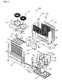
- Fig. 1 is an exploded perspective view illustrating an outdoor unit of an air conditioner according to an embodiment.
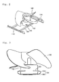
- Fig. 2 is a perspective view of a main part according to an embodiment.
- Fig. 3 is a longitudinal sectional view of a main part according to an embodiment.
- Fig. 4 is an exploded perspective view illustrating an outdoor unit of an air conditioner according to another embodiment.
- Fig. 5 is a longitudinal sectional view of a main part according to another embodiment.
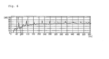
- Fig. 6 is a graph illustrating a reduced noise of an outdoor unit of an air conditioner according to another embodiment.
- a base pan 110 defines a bottom surface of an outdoor unit 100.
- a variety of parts, which will be described below, constituting a heat-exchanger are installed on a top surface of the base pan 110.
- a front panel 112 defining an outer appearance of a front portion is positioned on a front end of the base pan 110.
- a front grill 114 is positioned on an upper side of the front panel 112. Outdoor air is guided into the outdoor unit 110 through the front grill 114.
- the air in the outdoor unit 110 is provided to an outdoor heat-exchanger 180 to be heat-exchanged with a refrigerant.
- a front bracket 116 is positioned on an upper end of the front grill 114.
- a motor mount 164 is coupled to the front bracket 116.
- Two compressors 120 and 120' are positioned on the top surface of the base pan 110.
- the compressors 120 and 120' compress the refrigerant into a high-pressure and high-temperature vapor refrigerant.
- the compressor 120 is a regular velocity type compressor and the compressor 120' is an inverter type compressor 120'.
- the regular velocity compressor 120 may be positioned on a right portion of the top surface of the base pan 110.
- An inverter compressor 120' which is a variable speed heat pump, may be positioned on a left portion of the top surface of the base pan 110 as shown in Fig. 1 .
- Oil separators 122 are positioned at outlet sides of the regular velocity compressor 120 and the inverter compressor 120', respectively.
- the oil separators 122 filter oil contained in the refrigerant provided from the compressors 120 and 120'.
- the filtered refrigerant returns to the compressors 120 and 120'.
- Check valves 122' are positioned at outlet sides of the oil separators 122, respectively. When one compressor of the regular velocity compressor 120 and the inverter compressor 120' is operated, the check valves 122' prevent the compressed refrigerant generated by a operating compressor from flowing backward into the other compressor that is in a stopped state.
- a 4-way valve 124 is connected to the respective oil separators 122 via pipes.
- the 4-way valve 124 changes a flow direction of the refrigerant according to a cooling or heating operation.
- Ports of the 4-way valve 124 are connected to respective outlets of the compressors 120 and 120', respective inlets of the compressors 120 and 120', and an indoor unit, respectively.
- the ports of the 4-way valve 124 may be connected to the oil separators of the compressors 120 and 120' instead of the outlets respectively.
- the ports of the 4-way valve 124 may be connected to an accumulator of the compressors 120 and 120' instead of the inlets.
- a valve support 126 is positioned on a central portion of the front end of the top surface of the base pan 110.
- the valve support 126 supports and guides an outdoor liquid pipe 210 through which a liquid refrigerant flows, an outdoor gas pipe 212 through which a gaseous refrigerant flows, and a high-low pressure common pipe 214 for maintaining balance of the refrigerant between the outdoor units 100 when a plurality of the outdoor units 100 is provided.
- a service valve 128 is positioned on the valve support 126.
- the pipes 210, 212, and 214 supported by the valve support 126 are connected to the indoor unit through pipe inlet/outlet ports 188' of side panels 188.
- a supercooler 130 is positioned on a left rear end of the top surface of the base pan 110.
- the supercooler 130 additionally cools the refrigerant, which is cooled in the outdoor heat-exchanger 180 by heat-exchange.
- the supercooler 130 may be positioned at a side of the outdoor liquid pipe 210 connected to an outlet side of the outdoor heat-exchanger 180.
- a drier is positioned at a side of the outdoor liquid pipe 210.
- the drier removes moisture contained in the refrigerant flowing into the outdoor liquid pipe 210.
- the accumulator 132 is positioned at a central portion of the base pan 110, e.g., between the regular velocity compressor 120 and the inverter compressor 120'.
- the accumulator 132 filters a liquefied refrigerant to provide a gaseous refrigerant into the compressors 120 and 120'. If the liquefied refrigerant, which is not evaporated into the gas provided from the indoor unit flows into the compressors 120 and 120', the compressors 120 and 120' compressing the refrigerant into the high-pressure and high-temperature vapor refrigerant increase a load.
- the liquefied refrigerant, which is not evaporated, flowing into the accumulator 132 is relatively heavy as compared to the gaseous refrigerant, the liquefied refrigerant is stored in a lower portion of the accumulator 132. Accordingly, the gaseous refrigerant stored in an upper portion of the accumulator 132 flows into the compressors 120 and 120'.
- Front frames 134 and 134' are positioned on both sides of the front end of the base pan 110, respectively.
- the front frames 134 and 134' are vertically positioned on both sides of the front end of the base pan 110.
- the front frames 134 and 134' are configured to fix the front bracket 116, the front grill 114, and a control box 200.
- a center frame 136 is positioned at the center of the outdoor unit 100 in a horizontal direction to fix the front frames 134. Both ends of the center frame 136 are coupled to the front frames 134 and 134', respectively.
- a barrier 140 is positioned on the center frame 136.
- the barrier 140 divides an inner space of the outdoor unit 100 into an upper space and a lower space.
- the barrier 140 divides an inner space of the outdoor unit 100 into a lower space in which the compressors 120 and 120' are positioned and an upper space in which the outdoor heat-exchanger 180 is positioned.
- the barrier 140 may be provided in a pair, each including a horizontal part 140' extending backwardly from the center frame 136 and an inclined portion 140" inclinedly extending downwardly from a rear end of the horizontal part 140' at a predetermined angle.
- An air guide hole 142 is defined in the horizontal part 140' of the barrier 140 as shown in Fig. 1 . Air that cools electrical components installed inside the control box 200 flows through the air guide hole 142.
- An upper panel 150 defines a top surface of the outdoor unit 100.
- the upper panel 150 may be provided in a pair, each having a rectangular shape.
- Discharge holes 152 are defined in the pair of upper panels 150, respectively.
- a shroud 154 having a cylindrical shape is positioned on a bottom surface of the upper panel 150 corresponding to a circumference of the discharge hole 152.
- the shroud 154 is substantially integrated with the upper panel 150 to guide air blown by a blow fan 160 to the outside.
- a discharge grill 156 is positioned on the discharge hole 152.
- the blow fan 160 is positioned inside of the shroud 154.
- the blow fan 160 generates a flow of air circulating into the inside of the outdoor unit 100. That is, when the blow fan 160 is operated, outdoor air is guided into the outdoor unit 100 through the front grill 114. The air is then heat-exchanged with the refrigerant flowing into the outdoor heat-exchanger 180. After the air is heat-exchanged with the refrigerant, the air flows in an upward direction by the operation of the blow fan 160. The air is discharged to outside of the outdoor unit 100 through the discharge hole 152 by the operation of the blow fan 160.
- a fan motor 162 is positioned inside the outdoor unit 100, e.g., below the blow fan 160.
- the fan motor 162 is fixed by the motor mount 164.
- Front and rear ends of the motor mount 164 are fixed by the front bracket 116 and a rear bracket 194, respectively.
- a plurality of mounting brackets 163 are positioned on the fan motor 162.
- the mounting brackets 163 fix the fan motor 162 to the motor mount 164.
- the mounting brackets 163 may be a linkage component such that the fan motor is fix by the motor mount 164.
- the fan motor 162 may be fixed by a pair of motor mounts 164.
- the motor mount 164 includes a motor mounting part 165 and an air guide part 166.
- the motor mounting part 165 has a ⁇ -shape (an upside-down L-shape) in cross-section. Both ends of the motor mounting part 165 are fixed by the front bracket 116 and the rear bracket 194, respectively.
- the air guide part 166 is inclined downwardly from one end of the motor mounting part 165 relatively spaced apart from the fan motor 162 toward the fan motor 162 in a longitudinal direction.
- the air guide part 166 extends in a longitudinal direction from one end of the motor mounting part 165 so that a flow area of a passage toward an upward direction is increased.
- the shape of the motor mount 164 may reduce the air flowing by the blow fan 160 from interfering with the motor mount 164.
- the outdoor heat-exchanger 180 is positioned inside of the outdoor unit 100,e.g., below the upper panel 150.
- the outdoor heat-exchanger 180 conducts heat-exchange between a refrigerant flowing into the outdoor heat-exchanger 180 and outdoor air.
- the outdoor heat-exchanger 180 includes a front heat-exchanger 182 positioned below a front end of the upper panel 150 and a rear heat-exchanger 184 positioned below a rear end of the upper panel 150.
- a drain pan 186 is positioned below the outdoor heat-exchanger 180.
- the drain pan 186 collects condensed water generated during heat-exchange between the refrigerant flowing into the outdoor heat-exchanger 180 and the outdoor air.
- the drain pan 186 also discharges the condensed water to the outside.
- the side panels 188 are positioned on both ends of the top surface of the base pan 110.
- the side panels 188 define lateral outer appearances of the outdoor unit 100.
- a plurality of inlet/outlet holes 188' are defined in lower portions of the side panels 188.
- the rear panel 190 is positioned on a rear end of the base pan 110.
- the rear panel 190 defines an outer appearance of the outdoor unit 100, for example, a rear lower portion of the outdoor unit 100.
- a rear grill 192 is positioned on an upper end of the rear panel 190.
- the outdoor air to be heat-exchanged with the refrigerant flowing into the outdoor-heat-exchanger 180 is guided into the outdoor unit 110 through the rear grill 192.
- the air guide in the rear grill 192 is as same as an air guide in the front grill 114.
- the size of the rear grill 192 may correspond to that of the rear heat-exchanger 184.
- the rear bracket 194 is positioned on an upper end of the rear grill 192.
- the rear bracket 194 is horizontally positioned in a left or a right direction.
- the motor mount 164 is fixed by the rear bracket 194.
- Rear frames 196 are positioned at both sides of the rear end of the base pan 110, respectively.
- the rear frames 196 are vertically disposed.
- the rear frames 196 fix the rear grill 192, the rear panel 190, the upper panel 150 and etc.
- the control box 200 is positioned on an upper portion of the front panel 112, for example, a rear part of the upper portion.
- a variety of electrical components for operating the outdoor unit 100 may be installed inside the control box 200.
- the control box 200 is cooled by air.
- the barrier 140 guides the air to cool the control box 200. Air that is passed through the air guide hole 142 flows into the control box 200. And the air flowing into the control box 200 cools the electrical components of the control box 200. Then, the air is discharged to the outside of the control box 200. For this discharging operation, an air suction hole and an air discharge hole 202 are defined in the control box 200.
- the gaseous refrigerant from the outdoor unit flows into the accumulator 132 through the 4-way valve 124.
- the gaseous refrigerant in which a portion of the liquefied refrigerant is filtered while the gaseous refrigerant passes through the accumulator 132 flows into the compressors 120 and 120'.
- the gaseous refrigerant flowing into the compressors 120 and 120' is compressed into a high-temperature and high-pressure, and then is transferred into the oil separator 122. Oil contained in the refrigerant transferred into the oil separator 122 is separated to return into the compressors 120 and 120'.
- the refrigerant passing through the oil separator 122 flows into the outdoor heat-exchanger 180 through the 4-way valve 124.
- the refrigerant flowing into the outdoor heat-exchanger 180 is heat-exchanged with the outdoor air guided into the outdoor unit 100 through the front grill 114 and the rear grill 192 by the operation of the blow fan 160 to cool the refrigerant.
- the refrigerant passing through the outdoor heat-exchanger 180 is additionally cooled while the refrigerant passes through the supercooler 130.
- the refrigerant passing through the supercooler 130 passes through the drier for removing the moisture contained therein, and then, passes through the outdoor liquid pipe 210 to flow into the indoor unit.
- the refrigerant flowing into the indoor unit is heat exchanged with the indoor air while the refrigerant flows into an indoor heat-exchanger positioned inside of the indoor unit to cool the indoor air. Thereafter, the refrigerant flows again into the outdoor unit 100.
- the air heat-exchanged with the refrigerant flowing into the outdoor heat-exchanger 180 is moved upwardly by a rotation of the blow fan 160.
- the air flowing upwardly by the rotation of the blow fan 160 is guided by the guide part 166 to flow into the outside of the motor mount 164, for example, the motor mounting part 165 of the motor mount 164.
- an air guide 170 reduces a vortex generated when air flows by a rotation of a blow fan 160 and interferes with a motor mount 164.
- the air guide 170 is detachably disposed on the motor mount 164 on which a fan motor 162 is mounted.
- the air guide 170 includes a guide 172, extending parts 174, and a hook part 176.
- the guide 172 is bent at a predetermined angle to have a V-shape in cross-section.
- the guide 172 guides the air flowing by the rotation of the blow fan 160 to reduce a flow of the air from interfering with the motor mount 164.
- the guide 172 guides the air flowing by the rotation of the blow fan 160 toward the outside of the motor mount 164.
- the extending parts 174 extend upwardly from both ends of the guide 172, respectively.
- the hook part 176 extends horizontally from an upper end of the extending parts 174.
- the hook part 176 is hooked on a top surface of the motor mount 164 in a state where the air guide 170 is mounted on the motor mount 164.
- a curved line A denotes a noise level based on an operation of a related art
- a curved line B denotes a noise level based on an operation of the present invention
- the air guide may be fixed to the motor mount with using a separate coupling member such as a screw.
- the interference between the outdoor air flowing by the blow fan and the motor mount can be reduced, the noise generated when the outdoor air flowing by the blow fan is heat exchanged with the refrigerant may be reduced.
Landscapes
- Engineering & Computer Science (AREA)
- Mechanical Engineering (AREA)
- General Engineering & Computer Science (AREA)
- Chemical & Material Sciences (AREA)
- Combustion & Propulsion (AREA)
- Life Sciences & Earth Sciences (AREA)
- Sustainable Development (AREA)
- Other Air-Conditioning Systems (AREA)
Applications Claiming Priority (1)
| Application Number | Priority Date | Filing Date | Title |
|---|---|---|---|
| KR1020090001984A KR101575904B1 (ko) | 2009-01-09 | 2009-01-09 | 팬모터 장착구조 및 이를 포함하는 공기조화기의 실외기 |
Publications (3)
| Publication Number | Publication Date |
|---|---|
| EP2206976A2 true EP2206976A2 (fr) | 2010-07-14 |
| EP2206976A3 EP2206976A3 (fr) | 2012-08-29 |
| EP2206976B1 EP2206976B1 (fr) | 2016-11-30 |
Family
ID=42115383
Family Applications (1)
| Application Number | Title | Priority Date | Filing Date |
|---|---|---|---|
| EP10000114.8A Not-in-force EP2206976B1 (fr) | 2009-01-09 | 2010-01-08 | Unité extérieure pour climatiseur |
Country Status (6)
| Country | Link |
|---|---|
| US (1) | US7971448B2 (fr) |
| EP (1) | EP2206976B1 (fr) |
| KR (1) | KR101575904B1 (fr) |
| CN (1) | CN102272532B (fr) |
| ES (1) | ES2616557T3 (fr) |
| WO (1) | WO2010079911A2 (fr) |
Cited By (9)
| Publication number | Priority date | Publication date | Assignee | Title |
|---|---|---|---|---|
| US20150159892A1 (en) * | 2013-12-05 | 2015-06-11 | Lg Electronics Inc. | Outdoor unit of air conditioner |
| EP2766666A4 (fr) * | 2011-10-13 | 2015-07-08 | Lg Electronics Inc | Climatiseur |
| EP2841866A4 (fr) * | 2012-04-26 | 2016-02-17 | Evapco Inc | Sous-ensemble de plateforme de ventilateur de condenseur refroidi par air |
| EP3034959A1 (fr) * | 2014-12-17 | 2016-06-22 | LG Electronics Inc. | Dispositif extérieur pour climatiseur |
| EP2889543A4 (fr) * | 2012-06-07 | 2016-07-20 | Mitsubishi Electric Corp | Unité extérieure de climatisation |
| EP2535660A3 (fr) * | 2011-06-13 | 2018-05-16 | Sanyo Electric Co., Ltd. | Unité extérieure pour climatiseur |
| US10041704B2 (en) | 2014-09-12 | 2018-08-07 | Lg Electronics Inc. | Outdoor device for an air conditioner |
| US10077910B2 (en) | 2014-09-12 | 2018-09-18 | Lg Electronics Inc. | Outdoor device for an air conditioner |
| EP4113021A4 (fr) * | 2020-02-26 | 2023-03-29 | Mitsubishi Electric Corporation | Unité extérieure et dispositif de climatisation |
Families Citing this family (14)
| Publication number | Priority date | Publication date | Assignee | Title |
|---|---|---|---|---|
| JP5877364B2 (ja) * | 2011-06-13 | 2016-03-08 | パナソニックIpマネジメント株式会社 | 空気調和装置の室外ユニット |
| KR101442387B1 (ko) * | 2013-01-14 | 2014-09-17 | 엘지전자 주식회사 | 모터 마운트 및 이를 포함하는 공기 조화기, 모터 마운트의 제조방법 |
| JP6385752B2 (ja) | 2013-12-02 | 2018-09-05 | 三星電子株式会社Samsung Electronics Co.,Ltd. | 送風装置及び空気調和装置用室外機 |
| JP6269717B2 (ja) * | 2016-04-21 | 2018-01-31 | ダイキン工業株式会社 | 熱源ユニット |
| WO2017195335A1 (fr) * | 2016-05-12 | 2017-11-16 | 三菱電機株式会社 | Unité extérieure de climatiseur |
| KR102596983B1 (ko) * | 2016-09-09 | 2023-11-02 | 삼성전자주식회사 | 공기조화기의 실외기 |
| KR200486742Y1 (ko) | 2016-12-19 | 2018-06-27 | 한전케이피에스 주식회사 | 실외기의 전동기 팬날개 분리 도움틀 |
| KR101929919B1 (ko) | 2017-01-12 | 2018-12-17 | 한전케이피에스 주식회사 | 가스터빈 로터 메리지 볼트 신장량 무선 측정시스템 |
| JP2018162904A (ja) * | 2017-03-24 | 2018-10-18 | 三菱重工サーマルシステムズ株式会社 | 室外機 |
| JP2019045038A (ja) * | 2017-08-31 | 2019-03-22 | アイシン精機株式会社 | 空気調和装置 |
| WO2019093833A1 (fr) * | 2017-11-13 | 2019-05-16 | Samsung Electronics Co., Ltd. | Soufflante et unité d'extérieur de climatiseur dotée de ladite soufflante |
| JP6773060B2 (ja) * | 2018-02-15 | 2020-10-21 | ダイキン工業株式会社 | 空気調和装置の室外機 |
| KR102844110B1 (ko) | 2020-09-21 | 2025-08-07 | 엘지전자 주식회사 | 공기조화기 |
| KR102438932B1 (ko) * | 2020-12-30 | 2022-08-31 | 엘지전자 주식회사 | 공기조화기의 실외기 |
Family Cites Families (13)
| Publication number | Priority date | Publication date | Assignee | Title |
|---|---|---|---|---|
| US4204409A (en) * | 1978-07-26 | 1980-05-27 | Satama Kauko K | Air conditioning apparatus and system |
| US4321803A (en) * | 1979-11-23 | 1982-03-30 | Addison Products Company | Multiple air passage condenser |
| ZA839309B (fr) * | 1983-06-06 | 1985-09-14 | ||
| US4815530A (en) * | 1987-03-10 | 1989-03-28 | Kool Kap Corp. | Kool kap |
| US5097678A (en) * | 1990-11-19 | 1992-03-24 | Aubuchon Steven L | Ventilating protective cover for top-discharge air conditioners |
| US5531267A (en) * | 1994-08-24 | 1996-07-02 | Emerson Electric Co. | Refrigeration centrifugal blower system |
| KR20030034967A (ko) | 2001-10-29 | 2003-05-09 | 이복현 | 공기조화기의 팬모터 설치구조 |
| KR100468472B1 (ko) | 2002-09-30 | 2005-01-27 | 삼성전자주식회사 | 공기조화기의 실외기 |
| US6964175B2 (en) * | 2003-11-14 | 2005-11-15 | Rajiv K. Karkhanis | Evaporative heat rejection |
| KR100621699B1 (ko) | 2005-01-12 | 2006-09-14 | 삼성전자주식회사 | 에어컨 실외기의 모터브라켓 |
| JP2006292196A (ja) | 2005-04-06 | 2006-10-26 | Matsushita Electric Ind Co Ltd | 空気調和機の室外ユニット |
| JP3985840B2 (ja) * | 2005-11-01 | 2007-10-03 | ダイキン工業株式会社 | 空気調和装置の室外ユニット |
| CN101292119B (zh) * | 2005-11-01 | 2011-07-06 | 大金工业株式会社 | 空调装置的室外单元 |
-
2009
- 2009-01-09 KR KR1020090001984A patent/KR101575904B1/ko not_active Expired - Fee Related
- 2009-12-30 US US12/649,389 patent/US7971448B2/en not_active Expired - Fee Related
-
2010
- 2010-01-07 WO PCT/KR2009/007756 patent/WO2010079911A2/fr not_active Ceased
- 2010-01-07 CN CN201080004218.4A patent/CN102272532B/zh not_active Expired - Fee Related
- 2010-01-08 ES ES10000114.8T patent/ES2616557T3/es active Active
- 2010-01-08 EP EP10000114.8A patent/EP2206976B1/fr not_active Not-in-force
Non-Patent Citations (1)
| Title |
|---|
| None |
Cited By (15)
| Publication number | Priority date | Publication date | Assignee | Title |
|---|---|---|---|---|
| EP2535660A3 (fr) * | 2011-06-13 | 2018-05-16 | Sanyo Electric Co., Ltd. | Unité extérieure pour climatiseur |
| US9494358B2 (en) | 2011-10-13 | 2016-11-15 | Lg Electronics Inc. | Air conditioner |
| EP2766666A4 (fr) * | 2011-10-13 | 2015-07-08 | Lg Electronics Inc | Climatiseur |
| EP2841866A4 (fr) * | 2012-04-26 | 2016-02-17 | Evapco Inc | Sous-ensemble de plateforme de ventilateur de condenseur refroidi par air |
| EP2889543A4 (fr) * | 2012-06-07 | 2016-07-20 | Mitsubishi Electric Corp | Unité extérieure de climatisation |
| US9702571B2 (en) | 2012-06-07 | 2017-07-11 | Mitsubishi Electric Corporation | Air conditioner outdoor unit |
| US20150159892A1 (en) * | 2013-12-05 | 2015-06-11 | Lg Electronics Inc. | Outdoor unit of air conditioner |
| EP2910863A1 (fr) * | 2013-12-05 | 2015-08-26 | LG Electronics Inc. | Unité extérieure pour climatiseur |
| US10041704B2 (en) | 2014-09-12 | 2018-08-07 | Lg Electronics Inc. | Outdoor device for an air conditioner |
| US10077910B2 (en) | 2014-09-12 | 2018-09-18 | Lg Electronics Inc. | Outdoor device for an air conditioner |
| EP3034959A1 (fr) * | 2014-12-17 | 2016-06-22 | LG Electronics Inc. | Dispositif extérieur pour climatiseur |
| US10443902B2 (en) | 2014-12-17 | 2019-10-15 | Lg Electronics Inc. | Outdoor device for an air conditioner |
| EP4113021A4 (fr) * | 2020-02-26 | 2023-03-29 | Mitsubishi Electric Corporation | Unité extérieure et dispositif de climatisation |
| AU2020431090B2 (en) * | 2020-02-26 | 2023-08-03 | Mitsubishi Electric Corporation | Outdoor unit and air conditioner |
| EP4318901A3 (fr) * | 2020-02-26 | 2024-04-03 | Mitsubishi Electric Corporation | Unité extérieure et dispositif de climatisation |
Also Published As
| Publication number | Publication date |
|---|---|
| CN102272532A (zh) | 2011-12-07 |
| ES2616557T3 (es) | 2017-06-13 |
| EP2206976A3 (fr) | 2012-08-29 |
| CN102272532B (zh) | 2014-05-14 |
| WO2010079911A3 (fr) | 2010-09-16 |
| US20100175407A1 (en) | 2010-07-15 |
| US7971448B2 (en) | 2011-07-05 |
| WO2010079911A2 (fr) | 2010-07-15 |
| EP2206976B1 (fr) | 2016-11-30 |
| KR101575904B1 (ko) | 2015-12-08 |
| KR20100082612A (ko) | 2010-07-19 |
Similar Documents
| Publication | Publication Date | Title |
|---|---|---|
| US7971448B2 (en) | Air conditioner | |
| CN105737274B (zh) | 空调机的室外机 | |
| CN105737279B (zh) | 空气调节器的室外机 | |
| EP2597384B1 (fr) | Unité extérieure pour climatiseur | |
| KR101457692B1 (ko) | 컨트롤박스 및 이를 포함하는 공기조화기의 실외기 | |
| JP2015102257A (ja) | 空気調和機 | |
| KR100765563B1 (ko) | 멀티형 공기조화기 | |
| KR100626455B1 (ko) | 멀티형 공기조화기 | |
| KR101442114B1 (ko) | 공기조화기 | |
| KR100593079B1 (ko) | 멀티형 공기조화기의 실외기 | |
| KR100593080B1 (ko) | 멀티형 공기조화기의 실외기 | |
| KR100593082B1 (ko) | 멀티형 공기조화기의 실외기 | |
| KR20050082476A (ko) | 공기조화기의 오일분리기 | |
| KR100593083B1 (ko) | 공기조화기의 실외기 시스템 | |
| KR20050075960A (ko) | 공기조화기의 오일분리기 구조 | |
| KR101024475B1 (ko) | 공기조화기의 압축기 오일 공급구조 | |
| KR100593081B1 (ko) | 멀티형 공기조화기의 실외기 | |
| KR20050075152A (ko) | 멀티형 공기조화기의 실외기 | |
| KR20050088539A (ko) | 멀티형 공기조화기 | |
| KR100584284B1 (ko) | 공기조화기 실외기의 상면판넬 결합구조 | |
| KR100671568B1 (ko) | 멀티형 공기조화기의 실외기 | |
| KR20050079463A (ko) | 공기조화기 | |
| KR20050081352A (ko) | 멀티형 공기조화기 | |
| KR20070090365A (ko) | 공기조화기의 실외기 | |
| KR20060082580A (ko) | 공기조화기의 오일분리기 장착구조 |
Legal Events
| Date | Code | Title | Description |
|---|---|---|---|
| PUAI | Public reference made under article 153(3) epc to a published international application that has entered the european phase |
Free format text: ORIGINAL CODE: 0009012 |
|
| AK | Designated contracting states |
Kind code of ref document: A2 Designated state(s): AT BE BG CH CY CZ DE DK EE ES FI FR GB GR HR HU IE IS IT LI LT LU LV MC MK MT NL NO PL PT RO SE SI SK SM TR |
|
| AX | Request for extension of the european patent |
Extension state: AL BA RS |
|
| PUAL | Search report despatched |
Free format text: ORIGINAL CODE: 0009013 |
|
| AK | Designated contracting states |
Kind code of ref document: A3 Designated state(s): AT BE BG CH CY CZ DE DK EE ES FI FR GB GR HR HU IE IS IT LI LT LU LV MC MK MT NL NO PL PT RO SE SI SK SM TR |
|
| AX | Request for extension of the european patent |
Extension state: AL BA RS |
|
| RIC1 | Information provided on ipc code assigned before grant |
Ipc: F24F 1/00 20110101AFI20120724BHEP Ipc: F04D 29/70 20060101ALI20120724BHEP |
|
| 17P | Request for examination filed |
Effective date: 20130226 |
|
| GRAP | Despatch of communication of intention to grant a patent |
Free format text: ORIGINAL CODE: EPIDOSNIGR1 |
|
| RIC1 | Information provided on ipc code assigned before grant |
Ipc: F04D 29/70 20060101ALI20160525BHEP Ipc: F24F 1/00 20110101AFI20160525BHEP |
|
| INTG | Intention to grant announced |
Effective date: 20160621 |
|
| RAP1 | Party data changed (applicant data changed or rights of an application transferred) |
Owner name: LG ELECTRONICS INC. |
|
| GRAS | Grant fee paid |
Free format text: ORIGINAL CODE: EPIDOSNIGR3 |
|
| GRAA | (expected) grant |
Free format text: ORIGINAL CODE: 0009210 |
|
| AK | Designated contracting states |
Kind code of ref document: B1 Designated state(s): AT BE BG CH CY CZ DE DK EE ES FI FR GB GR HR HU IE IS IT LI LT LU LV MC MK MT NL NO PL PT RO SE SI SK SM TR |
|
| REG | Reference to a national code |
Ref country code: CH Ref legal event code: EP Ref country code: GB Ref legal event code: FG4D |
|
| REG | Reference to a national code |
Ref country code: AT Ref legal event code: REF Ref document number: 850171 Country of ref document: AT Kind code of ref document: T Effective date: 20161215 |
|
| REG | Reference to a national code |
Ref country code: IE Ref legal event code: FG4D |
|
| REG | Reference to a national code |
Ref country code: DE Ref legal event code: R096 Ref document number: 602010038364 Country of ref document: DE |
|
| REG | Reference to a national code |
Ref country code: FR Ref legal event code: PLFP Year of fee payment: 8 |
|
| PG25 | Lapsed in a contracting state [announced via postgrant information from national office to epo] |
Ref country code: LV Free format text: LAPSE BECAUSE OF FAILURE TO SUBMIT A TRANSLATION OF THE DESCRIPTION OR TO PAY THE FEE WITHIN THE PRESCRIBED TIME-LIMIT Effective date: 20161130 |
|
| REG | Reference to a national code |
Ref country code: LT Ref legal event code: MG4D |
|
| REG | Reference to a national code |
Ref country code: NL Ref legal event code: MP Effective date: 20161130 |
|
| REG | Reference to a national code |
Ref country code: AT Ref legal event code: MK05 Ref document number: 850171 Country of ref document: AT Kind code of ref document: T Effective date: 20161130 |
|
| PG25 | Lapsed in a contracting state [announced via postgrant information from national office to epo] |
Ref country code: SE Free format text: LAPSE BECAUSE OF FAILURE TO SUBMIT A TRANSLATION OF THE DESCRIPTION OR TO PAY THE FEE WITHIN THE PRESCRIBED TIME-LIMIT Effective date: 20161130 Ref country code: NO Free format text: LAPSE BECAUSE OF FAILURE TO SUBMIT A TRANSLATION OF THE DESCRIPTION OR TO PAY THE FEE WITHIN THE PRESCRIBED TIME-LIMIT Effective date: 20170228 Ref country code: LT Free format text: LAPSE BECAUSE OF FAILURE TO SUBMIT A TRANSLATION OF THE DESCRIPTION OR TO PAY THE FEE WITHIN THE PRESCRIBED TIME-LIMIT Effective date: 20161130 Ref country code: GR Free format text: LAPSE BECAUSE OF FAILURE TO SUBMIT A TRANSLATION OF THE DESCRIPTION OR TO PAY THE FEE WITHIN THE PRESCRIBED TIME-LIMIT Effective date: 20170301 |
|
| PG25 | Lapsed in a contracting state [announced via postgrant information from national office to epo] |
Ref country code: PL Free format text: LAPSE BECAUSE OF FAILURE TO SUBMIT A TRANSLATION OF THE DESCRIPTION OR TO PAY THE FEE WITHIN THE PRESCRIBED TIME-LIMIT Effective date: 20161130 Ref country code: PT Free format text: LAPSE BECAUSE OF FAILURE TO SUBMIT A TRANSLATION OF THE DESCRIPTION OR TO PAY THE FEE WITHIN THE PRESCRIBED TIME-LIMIT Effective date: 20170330 Ref country code: FI Free format text: LAPSE BECAUSE OF FAILURE TO SUBMIT A TRANSLATION OF THE DESCRIPTION OR TO PAY THE FEE WITHIN THE PRESCRIBED TIME-LIMIT Effective date: 20161130 Ref country code: AT Free format text: LAPSE BECAUSE OF FAILURE TO SUBMIT A TRANSLATION OF THE DESCRIPTION OR TO PAY THE FEE WITHIN THE PRESCRIBED TIME-LIMIT Effective date: 20161130 Ref country code: BE Free format text: LAPSE BECAUSE OF NON-PAYMENT OF DUE FEES Effective date: 20170131 Ref country code: HR Free format text: LAPSE BECAUSE OF FAILURE TO SUBMIT A TRANSLATION OF THE DESCRIPTION OR TO PAY THE FEE WITHIN THE PRESCRIBED TIME-LIMIT Effective date: 20161130 |
|
| REG | Reference to a national code |
Ref country code: ES Ref legal event code: FG2A Ref document number: 2616557 Country of ref document: ES Kind code of ref document: T3 Effective date: 20170613 |
|
| PG25 | Lapsed in a contracting state [announced via postgrant information from national office to epo] |
Ref country code: NL Free format text: LAPSE BECAUSE OF FAILURE TO SUBMIT A TRANSLATION OF THE DESCRIPTION OR TO PAY THE FEE WITHIN THE PRESCRIBED TIME-LIMIT Effective date: 20161130 |
|
| PG25 | Lapsed in a contracting state [announced via postgrant information from national office to epo] |
Ref country code: DK Free format text: LAPSE BECAUSE OF FAILURE TO SUBMIT A TRANSLATION OF THE DESCRIPTION OR TO PAY THE FEE WITHIN THE PRESCRIBED TIME-LIMIT Effective date: 20161130 Ref country code: EE Free format text: LAPSE BECAUSE OF FAILURE TO SUBMIT A TRANSLATION OF THE DESCRIPTION OR TO PAY THE FEE WITHIN THE PRESCRIBED TIME-LIMIT Effective date: 20161130 Ref country code: RO Free format text: LAPSE BECAUSE OF FAILURE TO SUBMIT A TRANSLATION OF THE DESCRIPTION OR TO PAY THE FEE WITHIN THE PRESCRIBED TIME-LIMIT Effective date: 20161130 Ref country code: CZ Free format text: LAPSE BECAUSE OF FAILURE TO SUBMIT A TRANSLATION OF THE DESCRIPTION OR TO PAY THE FEE WITHIN THE PRESCRIBED TIME-LIMIT Effective date: 20161130 Ref country code: SK Free format text: LAPSE BECAUSE OF FAILURE TO SUBMIT A TRANSLATION OF THE DESCRIPTION OR TO PAY THE FEE WITHIN THE PRESCRIBED TIME-LIMIT Effective date: 20161130 |
|
| REG | Reference to a national code |
Ref country code: DE Ref legal event code: R119 Ref document number: 602010038364 Country of ref document: DE |
|
| PG25 | Lapsed in a contracting state [announced via postgrant information from national office to epo] |
Ref country code: IT Free format text: LAPSE BECAUSE OF FAILURE TO SUBMIT A TRANSLATION OF THE DESCRIPTION OR TO PAY THE FEE WITHIN THE PRESCRIBED TIME-LIMIT Effective date: 20161130 Ref country code: BG Free format text: LAPSE BECAUSE OF FAILURE TO SUBMIT A TRANSLATION OF THE DESCRIPTION OR TO PAY THE FEE WITHIN THE PRESCRIBED TIME-LIMIT Effective date: 20170228 Ref country code: BE Free format text: LAPSE BECAUSE OF FAILURE TO SUBMIT A TRANSLATION OF THE DESCRIPTION OR TO PAY THE FEE WITHIN THE PRESCRIBED TIME-LIMIT Effective date: 20161130 Ref country code: SM Free format text: LAPSE BECAUSE OF FAILURE TO SUBMIT A TRANSLATION OF THE DESCRIPTION OR TO PAY THE FEE WITHIN THE PRESCRIBED TIME-LIMIT Effective date: 20161130 |
|
| REG | Reference to a national code |
Ref country code: CH Ref legal event code: PL |
|
| PG25 | Lapsed in a contracting state [announced via postgrant information from national office to epo] |
Ref country code: MC Free format text: LAPSE BECAUSE OF FAILURE TO SUBMIT A TRANSLATION OF THE DESCRIPTION OR TO PAY THE FEE WITHIN THE PRESCRIBED TIME-LIMIT Effective date: 20161130 |
|
| PLBE | No opposition filed within time limit |
Free format text: ORIGINAL CODE: 0009261 |
|
| STAA | Information on the status of an ep patent application or granted ep patent |
Free format text: STATUS: NO OPPOSITION FILED WITHIN TIME LIMIT |
|
| GBPC | Gb: european patent ceased through non-payment of renewal fee |
Effective date: 20170228 |
|
| PG25 | Lapsed in a contracting state [announced via postgrant information from national office to epo] |
Ref country code: CH Free format text: LAPSE BECAUSE OF NON-PAYMENT OF DUE FEES Effective date: 20170131 Ref country code: LI Free format text: LAPSE BECAUSE OF NON-PAYMENT OF DUE FEES Effective date: 20170131 |
|
| REG | Reference to a national code |
Ref country code: IE Ref legal event code: MM4A |
|
| 26N | No opposition filed |
Effective date: 20170831 |
|
| PG25 | Lapsed in a contracting state [announced via postgrant information from national office to epo] |
Ref country code: DE Free format text: LAPSE BECAUSE OF NON-PAYMENT OF DUE FEES Effective date: 20170801 Ref country code: SI Free format text: LAPSE BECAUSE OF FAILURE TO SUBMIT A TRANSLATION OF THE DESCRIPTION OR TO PAY THE FEE WITHIN THE PRESCRIBED TIME-LIMIT Effective date: 20161130 Ref country code: LU Free format text: LAPSE BECAUSE OF NON-PAYMENT OF DUE FEES Effective date: 20170108 |
|
| REG | Reference to a national code |
Ref country code: FR Ref legal event code: PLFP Year of fee payment: 9 |
|
| PG25 | Lapsed in a contracting state [announced via postgrant information from national office to epo] |
Ref country code: GB Free format text: LAPSE BECAUSE OF NON-PAYMENT OF DUE FEES Effective date: 20170228 Ref country code: IE Free format text: LAPSE BECAUSE OF NON-PAYMENT OF DUE FEES Effective date: 20170108 |
|
| PG25 | Lapsed in a contracting state [announced via postgrant information from national office to epo] |
Ref country code: MT Free format text: LAPSE BECAUSE OF NON-PAYMENT OF DUE FEES Effective date: 20170108 |
|
| PGFP | Annual fee paid to national office [announced via postgrant information from national office to epo] |
Ref country code: ES Payment date: 20190212 Year of fee payment: 10 |
|
| PG25 | Lapsed in a contracting state [announced via postgrant information from national office to epo] |
Ref country code: HU Free format text: LAPSE BECAUSE OF FAILURE TO SUBMIT A TRANSLATION OF THE DESCRIPTION OR TO PAY THE FEE WITHIN THE PRESCRIBED TIME-LIMIT; INVALID AB INITIO Effective date: 20100108 |
|
| PG25 | Lapsed in a contracting state [announced via postgrant information from national office to epo] |
Ref country code: CY Free format text: LAPSE BECAUSE OF NON-PAYMENT OF DUE FEES Effective date: 20161130 |
|
| PG25 | Lapsed in a contracting state [announced via postgrant information from national office to epo] |
Ref country code: MK Free format text: LAPSE BECAUSE OF FAILURE TO SUBMIT A TRANSLATION OF THE DESCRIPTION OR TO PAY THE FEE WITHIN THE PRESCRIBED TIME-LIMIT Effective date: 20161130 |
|
| PG25 | Lapsed in a contracting state [announced via postgrant information from national office to epo] |
Ref country code: TR Free format text: LAPSE BECAUSE OF FAILURE TO SUBMIT A TRANSLATION OF THE DESCRIPTION OR TO PAY THE FEE WITHIN THE PRESCRIBED TIME-LIMIT Effective date: 20161130 |
|
| PG25 | Lapsed in a contracting state [announced via postgrant information from national office to epo] |
Ref country code: IS Free format text: LAPSE BECAUSE OF FAILURE TO SUBMIT A TRANSLATION OF THE DESCRIPTION OR TO PAY THE FEE WITHIN THE PRESCRIBED TIME-LIMIT Effective date: 20170330 |
|
| REG | Reference to a national code |
Ref country code: ES Ref legal event code: FD2A Effective date: 20210602 |
|
| PG25 | Lapsed in a contracting state [announced via postgrant information from national office to epo] |
Ref country code: ES Free format text: LAPSE BECAUSE OF NON-PAYMENT OF DUE FEES Effective date: 20200109 |
|
| PGFP | Annual fee paid to national office [announced via postgrant information from national office to epo] |
Ref country code: FR Payment date: 20211208 Year of fee payment: 13 |
|
| PG25 | Lapsed in a contracting state [announced via postgrant information from national office to epo] |
Ref country code: FR Free format text: LAPSE BECAUSE OF NON-PAYMENT OF DUE FEES Effective date: 20230131 |