EP2208551A2 - Procédé de fabrication d'une pièce de tôle préformée complexe - Google Patents
Procédé de fabrication d'une pièce de tôle préformée complexe Download PDFInfo
- Publication number
- EP2208551A2 EP2208551A2 EP09015648A EP09015648A EP2208551A2 EP 2208551 A2 EP2208551 A2 EP 2208551A2 EP 09015648 A EP09015648 A EP 09015648A EP 09015648 A EP09015648 A EP 09015648A EP 2208551 A2 EP2208551 A2 EP 2208551A2
- Authority
- EP
- European Patent Office
- Prior art keywords
- sheet metal
- tool
- forming
- metal part
- contour line
- Prior art date
- Legal status (The legal status is an assumption and is not a legal conclusion. Google has not performed a legal analysis and makes no representation as to the accuracy of the status listed.)
- Granted
Links
- 239000002184 metal Substances 0.000 title claims abstract description 74
- 238000004519 manufacturing process Methods 0.000 title description 5
- 238000000034 method Methods 0.000 claims abstract description 34
- 238000005520 cutting process Methods 0.000 claims abstract description 5
- 238000005452 bending Methods 0.000 claims description 20
- 239000000463 material Substances 0.000 claims description 20
- 238000011161 development Methods 0.000 claims description 13
- 238000003825 pressing Methods 0.000 claims description 8
- 239000007769 metal material Substances 0.000 claims description 6
- 230000015572 biosynthetic process Effects 0.000 claims description 4
- 238000000465 moulding Methods 0.000 claims description 4
- 230000009466 transformation Effects 0.000 abstract description 3
- 238000012545 processing Methods 0.000 abstract description 2
- 238000007493 shaping process Methods 0.000 description 20
- 230000018109 developmental process Effects 0.000 description 12
- 238000005482 strain hardening Methods 0.000 description 6
- 230000000052 comparative effect Effects 0.000 description 2
- 230000006835 compression Effects 0.000 description 2
- 238000007906 compression Methods 0.000 description 2
- 238000012938 design process Methods 0.000 description 2
- 238000004140 cleaning Methods 0.000 description 1
- 230000001419 dependent effect Effects 0.000 description 1
- 238000009826 distribution Methods 0.000 description 1
- 238000005553 drilling Methods 0.000 description 1
- 230000002349 favourable effect Effects 0.000 description 1
- 239000000314 lubricant Substances 0.000 description 1
- 239000011159 matrix material Substances 0.000 description 1
- 238000010422 painting Methods 0.000 description 1
- 230000000284 resting effect Effects 0.000 description 1
- 238000004904 shortening Methods 0.000 description 1
- 230000000087 stabilizing effect Effects 0.000 description 1
- 238000012546 transfer Methods 0.000 description 1
- 238000009966 trimming Methods 0.000 description 1
- 238000011144 upstream manufacturing Methods 0.000 description 1
Images


Classifications
-
- B—PERFORMING OPERATIONS; TRANSPORTING
- B21—MECHANICAL METAL-WORKING WITHOUT ESSENTIALLY REMOVING MATERIAL; PUNCHING METAL
- B21D—WORKING OR PROCESSING OF SHEET METAL OR METAL TUBES, RODS OR PROFILES WITHOUT ESSENTIALLY REMOVING MATERIAL; PUNCHING METAL
- B21D22/00—Shaping without cutting, by stamping, spinning, or deep-drawing
- B21D22/02—Stamping using rigid devices or tools
-
- B—PERFORMING OPERATIONS; TRANSPORTING
- B21—MECHANICAL METAL-WORKING WITHOUT ESSENTIALLY REMOVING MATERIAL; PUNCHING METAL
- B21D—WORKING OR PROCESSING OF SHEET METAL OR METAL TUBES, RODS OR PROFILES WITHOUT ESSENTIALLY REMOVING MATERIAL; PUNCHING METAL
- B21D53/00—Making other particular articles
- B21D53/88—Making other particular articles other parts for vehicles, e.g. cowlings, mudguards
-
- B—PERFORMING OPERATIONS; TRANSPORTING
- B21—MECHANICAL METAL-WORKING WITHOUT ESSENTIALLY REMOVING MATERIAL; PUNCHING METAL
- B21D—WORKING OR PROCESSING OF SHEET METAL OR METAL TUBES, RODS OR PROFILES WITHOUT ESSENTIALLY REMOVING MATERIAL; PUNCHING METAL
- B21D19/00—Flanging or other edge treatment, e.g. of tubes
- B21D19/08—Flanging or other edge treatment, e.g. of tubes by single or successive action of pressing tools, e.g. vice jaws
Definitions
- the invention relates to a method for producing a complex sheet metal part, as well as a complex sheet metal part produced by this method.
- a complex sheet metal part is understood in the context of this invention, due to its spatial shape or shape only consuming writable sheet metal part.
- a complex sheet-metal shaped part can be composed or formed from many individual, even curved, surface sections. Due to its complex shape, such a complex sheet metal part according to the current state of the art can only be produced in a complex manner.
- the complex sheet metal parts are simply shaped sheet metal parts opposite, which can be easily described and produced in a simple manner, for example. By simple bending operations or the like.
- Body parts for motor vehicles in particular body panels and structural parts, are often complex sheet metal parts.
- An object of the invention is to provide a comparatively favorable possibility to be able to provide complex sheet-metal shaped parts with a high quality level.
- ruled surfaces and / or free-form surfaces and a plurality of contour lines are formed.
- a plurality of free-form surfaces is formed.
- at least one free-form surface is formed, which is delimited at least in sections by at least one contour line.
- control surface can be understood to mean a surface or a surface section which can be described mathematically simply. Ruled surfaces can in particular be planes, one-dimensionally curved surfaces with constant radii of curvature, lateral surfaces of cylinders, cones and the like.
- free-form surface can be understood to mean a complex, preferably multi-curved surface which, in particular, can not be mathematically described by simple geometric basic forms such as straight line, circle and conic section.
- a free-form surface can, for example, have complex concave and / or convex sections.
- a ruled surface and a free-form surface are characterized in particular by the fact that they have only a slight change in shape (comparative shape change). In the case of work hardening sheet metal materials, this change in shape is particularly so small that no appreciable cold work hardening occurs during forming.
- a "contour line” is understood to mean a bending line or a bending edge.
- Such a contour line is defined essentially by its spatial course, its bending angle and / or its bending radius.
- a contour line preferably has a curved and in particular a spatially multiply curved course.
- the bend radius and / or the bend angle may vary along the course.
- the bending contour can deviate from a circle segment.
- the bending angle is chosen so that a crack-free forming is guaranteed.
- the bending radius is at least partially selected so that when forming a cold work hardening sheet material, a work hardening occurs.
- the output board essentially corresponds to a precise development of the ready-to-install sheet metal part. This implies that during the forming no stretching or compression of the sheet material takes place, so that the starting sheet thickness is maintained in an advantageous manner over the entire sheet metal part. An exception is formed by the regions of the contour lines in which, in particular, bending shortening can occur, which can certainly be taken into account in the development of the sheet metal part, which is indicated by the wording "substantially.”
- the cutting determination preferably takes place by means of CAD systems.
- the invention is based on the idea of designing a complex shaped sheet metal part such that it comprises rule surfaces and / or free-form surfaces which are separated from one another by means of at least one contour line or subdivided by means of this contour line.
- the ruled surfaces and / or free-form surfaces are defined here by the spatial progression of an adjacent contour line or of all adjacent contour lines. That The spatial shape or the shape of the adjacent surfaces or surface sections is predetermined or determined by the spatial progression of a contour line.
- the sheet metal part In the previous design process and in particular in the 3D geometry determination for the sheet metal part is about to divide the overall geometry in individual rule surfaces and / or free-form surfaces and starting from the spatial shape of these individual areas or surface sections suitable gradients for the contour lines, and suitable bending angle and / or bending radii to define, with the reverse sequence is possible.
- the shape of the sheet metal part must also be developable in the plane, as explained above.
- the invention has many advantages.
- the forming takes place essentially in only one main forming stage, for which only one forming tool and only one forming press are required. Due to the resulting low investment costs, the invention is therefore particularly suitable for small quantities and small batches. However, this does not preclude the fact that the Hauptumformwork follow other Umformworkn or may be upstream.
- the sheet metal parts produced by the process according to the invention to a high level of quality, which is quite close to the quality of deep-drawn metal parts, although in the production of sheet metal parts according to the invention explicitly no deep-drawing process is performed. But that does not contradict that the method according to the invention can be combined with a deep drawing process. Furthermore arise for the design process of the sheet metal part new degrees of freedom.
- a front flap with integrated side walls or a complete floor assembly for a motor vehicle which is usually realized in the art by a plurality of sheet metal parts joined together and thus is correspondingly complex and costly.
- the forming takes place between a substantially rigid lower and a substantially rigid upper tool part, which are arranged in a forming press, wherein at least one of these tool parts has at least one closed shaping tool contour.
- all tool parts that are directly involved in forming have a closed shaping tool contour.
- the tool parts can also be referred to as upper tool and lower tool. These can each be constructed in several parts. By using rigid tool parts, the quality of the produced sheet metal parts can be improved.
- a bend (of the sheet metal material) takes place with a small bending radius.
- the term "small” here refers in particular to the relationship between the bending radius and the starting sheet thickness. Preferably, this ratio is in the range between 5 and 10 and in particular in the range between 2 and 5.
- the inventive method advantageously offers the possibility of defined formation of small radii and very small radii despite large depths of form, and this in particular even at high forming speeds.
- the application can be done, for example, by means of the upper tool to a shaping tool contour in the lower tool, or vice versa.
- the use of lubricant can thus largely be dispensed with; in addition, sheet metal materials with coated, pretreated and / or ready-to-install surfaces, in particular painted surfaces, can be used. Also, a hold-down is not required, so that a Ziehflansch deleted and sheet material is saved.
- a pressing operation is carried out, in which at least one contour line (of the sheet metal part) is finally formed or pronounced.
- This pressing operation is preferably carried out in the same forming tool and with high pressing forces, which are a multiple of the previous forming forces.
- At least one control surface and / or free-form surface of the sheet metal part is at least partially provided with a structuring of increasing stiffness during a pressing operation.
- Such structuring may be, for example, an embossed honeycomb structure or the like.
- the positioning of the output board in the forming tool takes place by means of at least one locking device.
- a locking device may, for example, be a simple locking pin or locking bolt.
- a suction device may be included in the forming tool.
- openings in the sheet metal part are formed by pre-apertures in the output board.
- Such openings may be bores, contoured recesses and the like. Starting from their position in the sheet metal part takes place through the plane Processing their positioning on the output board. This makes it possible to dispense with subsequent expensive cutting tools.
- the final forming of at least one contour line (of the sheet-metal shaped part) or a folding or edge-edge takes place by means of a separately movable tool part of the same forming tool.
- a separately movable tool part of the same forming tool can be produced.
- the separate tool part can be actuated, for example, by means of an auxiliary ram or a die cushion of the forming press.
- a complex shaped sheet metal part according to the invention is produced by the process according to the invention.
- This comprises at least two ruled surfaces and / or free-form surfaces which are delimited from one another by at least one contour line, wherein the ruled surfaces and / or free-form surfaces have a relatively small change in shape over their entire extent and a stiffness of the sheet metal part to a substantial proportion of the at least one Contour line results.
- the rigidity can be, for example, the overall stiffness (for example, relevant to the crash case), the torsional stiffness or the average buckling stiffness.
- the rigidity of the sheet metal part results in particular from the prevailing stresses in the control surfaces and / or the free-form surfaces, from a possible structuring of these surfaces, from the bending resistance of all contour lines, from the stress distribution of sheet metal top to sheet metal bottom especially in the region of these contour lines and from a work hardening along of these contour lines.
- the stiffness of the sheet metal part is to result in a substantial proportion of at least one contour lines and preferably from the totality of all contour lines insofar as the control surfaces and / or free-form surfaces are stabilized by the adjacent contour lines.
- a contour line in particular also prevents an elastic return of an adjacent free-form surface.
- the complex sheet-metal shaped part according to the invention has, in the region of at least one contour line, at least in sections, a locally high change in shape (comparative shape change).
- the change in shape is preferably so great that a clear work hardening occurs in the sheet material, as already explained above in connection with the term "contour line”.
- Fig. 1 shows the inventive method for producing a complex sheet metal part in a schematic overview. The sequence of the process takes place according to the illustration from bottom left to top right, which is symbolized by the arrows.
- the method comprises first providing a finished trimmed output board 10 made of a sheet metal material.
- the contour of the output board 10 essentially corresponds to a precise development of the product to be produced Sheet metal part.
- the output board 10 comprises pre-punched openings in the form of contoured recesses 12 and holes 14.
- the output board 10 is positioned in a forming tool 20 with an upper tool 22 and a lower tool 25.
- the forming tool 20 is installed in a forming press, not shown.
- a forming of the output board 10 to a sheet metal part 30 such that here ruled surfaces and / or free-form surfaces 32 are formed, which delimited by at least one contour line 34 from each other at least in sections , limited or limited.
- a contour line 34 is a spatially extending bending line or bending edge.
- the illustrated sheet metal part 30 is an example of a front flap of a motor vehicle. The transformation from the output board 10 to the sheet metal part 30 takes place in only one forming stage (Hauptumformcut). After this transformation, no trimming of the sheet metal part 30 is required.
- the sheet metal part 30 is as it were ready to install, subject to any cleaning and / or painting or the like.
- the forming of the output board 10 to the sheet metal part 30 by the forming tool 20 is shown schematically in the Fig. 2a and 2b shown.
- Fig. 2a shows the inserted between upper tool 22 and lower tool 25 output board 10. This is smaller in size than the shaping tool contours 23 and 26 of the upper tool 22 and the lower tool 25.
- the output board 10 is formed.
- the reshaping takes place in such a way that the sheet material of the output board 10 successively and / or in sections starting from at least one eg. Highest contact point to the closed forming tool contours 23 and / or 26, wherein in the following a relative movement between the adjacent sheet material and the forming tool 20 is largely avoided.
- the output sheet thickness of the output board 10 is maintained over the entire sheet metal molding 30. Consequently also have the introduced into the output board 10 openings 12 and 14 in the finished molded sheet metal part 30 their exact position and geometry, as in Fig. 1 indicated.
- Fig. 2b shows the closed forming tool 20.
- the output board 10 has been here converted in the manner described above to the sheet metal molding 30.
- a pressing operation can be carried out with high pressing forces in order to finally form at least one contour line 34 and / or to provide at least one control surface and / or free-form surface 32 with a stabilizing and stiffness-increasing structuring.
- This structuring is introduced by the shaping tool contours 23 and / or 26 in the sheet metal molding 30.
- Fig. 3a shows the output board 10 in a plan view, which when forming after the Fig. 2 is used. Shown here are the forming during forming contour lines 34th Fig. 3b shows the produced sheet metal part 30 in a perspective view with the ruled surfaces and / or free-form surfaces 32, which are delimited by the contour lines 34 to each other.
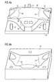
- Fig. 4a shows the lower tool 25 of the forming tool 20 in a perspective view. This includes a closed shaping tool contour 26 and three tool guides 27 for the upper tool 22. Also shown is a resting on the tool contour 26 finished molded sheet metal part 30, which in the manner described above from the output board 10 by successive and / or sectional application of the sheet material was made to the shaping tool contour 26 and can be removed from the forming tool 20 in the state shown.
- Fig. 4b shows that to Fig. 4a corresponding, turned upper tool 22 in a perspective view.
- This comprises a shaping tool contour 23, which is formed as a negative contour to the shaping tool contour 26 of the lower tool 25 with an offset.
- the application of the sheet material to the tool contour 26 of the lower tool 25 by means of the shaping tool contour 23 in the upper tool 22 (or vice versa), without a Relative movement between the sheet material and the shaping tool contours 23 and 26 is given.
- the shaping tool contours 23 and 26 comprise corresponding shaping sections, which are shown schematically in the illustrated upper tool 22 and designated by the reference numeral 24 and which the sheet material during closing and in particular compression of the forming tool 20 against corresponding shaping sections of the shaping tool contour 26 in Press lower tool 25 (or vice versa) to thereby form a contour line 34 exactly.
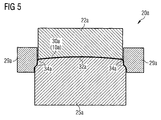
- Fig. 5 shows an alternative or supplementary possibility for forming at least one contour line.
- the same components are designated by the same reference numerals but with the addition "a”.
- the forming tool 20a comprises, in addition to the upper tool 22a and the lower tool 25a, a tool part 29a which is movable separately and parallel to the upper tool 22a.
- a formation of ruled surfaces and / or free-form surfaces 32a takes place between the shaping tool contours of the upper tool 22a and the lower tool 25a.
- a formation of contour lines 34a, by the tool part 29a is moved downward as shown, wherein initially a folding or stopping the sheet material down.
- the separate tool part 29a can be moved by the auxiliary ram of a forming press. Alternatively and / or additionally, a separate tool part can also be moved from below, for example by means of the drawing cushion of the forming press. In the same way, undercut can also be produced on the sheet-metal shaped part 30a, for example by means of a laterally displaceable separate tool part.
Landscapes
- Engineering & Computer Science (AREA)
- Mechanical Engineering (AREA)
- Shaping Metal By Deep-Drawing, Or The Like (AREA)
- Bending Of Plates, Rods, And Pipes (AREA)
Applications Claiming Priority (1)
| Application Number | Priority Date | Filing Date | Title |
|---|---|---|---|
| DE102009005261A DE102009005261A1 (de) | 2009-01-20 | 2009-01-20 | Verfahren zur Herstellung eines komplexen Blechformteils |
Publications (3)
| Publication Number | Publication Date |
|---|---|
| EP2208551A2 true EP2208551A2 (fr) | 2010-07-21 |
| EP2208551A3 EP2208551A3 (fr) | 2013-07-31 |
| EP2208551B1 EP2208551B1 (fr) | 2016-04-06 |
Family
ID=42144900
Family Applications (1)
| Application Number | Title | Priority Date | Filing Date |
|---|---|---|---|
| EP09015648.0A Active EP2208551B1 (fr) | 2009-01-20 | 2009-12-17 | Procédé de fabrication d'une pièce de tôle préformée complexe |
Country Status (2)
| Country | Link |
|---|---|
| EP (1) | EP2208551B1 (fr) |
| DE (1) | DE102009005261A1 (fr) |
Cited By (7)
| Publication number | Priority date | Publication date | Assignee | Title |
|---|---|---|---|---|
| CN102343405A (zh) * | 2011-06-28 | 2012-02-08 | 天津汽车模具股份有限公司 | 一种用于汽车外板覆盖件冲压的定位方法 |
| WO2014049070A1 (fr) * | 2012-09-26 | 2014-04-03 | Jaguar Land Rover Limited | Procédé et appareil de mise en forme de panneau |
| FR3035805A1 (fr) * | 2015-05-05 | 2016-11-11 | Peugeot Citroen Automobiles Sa | Procede de realisation d’une piece comportant une etape de formage et piece de structure de vehicule formee par un tel procede |
| WO2016185105A1 (fr) * | 2015-05-18 | 2016-11-24 | Peugeot Citroen Automobiles Sa | Mise a forme d'embouti semi-ouvert |
| WO2016177962A3 (fr) * | 2015-05-05 | 2017-04-13 | Peugeot Citroen Automobiles Sa | Procédé de réalisation simplifié d'une pièce, pièce obtenue par un tel procédé de realisation et procédé de sélection entre un procédé de réalisation simplifié ou non simplifié |
| FR3050666A1 (fr) * | 2016-05-02 | 2017-11-03 | Peugeot Citroen Automobiles Sa | Procede de realisation simplifie d’une piece, piece obtenue par un tel procede de realisation et procede de selection entre un procede de realisation simplifie ou non simplifie |
| CN114603060A (zh) * | 2022-02-17 | 2022-06-10 | 四川国腾设备制造有限公司 | 一种飞机发动机机罩的生产方法 |
Families Citing this family (1)
| Publication number | Priority date | Publication date | Assignee | Title |
|---|---|---|---|---|
| DE102013011951A1 (de) * | 2013-07-18 | 2015-01-22 | GM Global Technology Operations LLC (n. d. Ges. d. Staates Delaware) | Verfahren zum Fertigen von Kraftfahrzeug-Karosserieteilen |
Citations (3)
| Publication number | Priority date | Publication date | Assignee | Title |
|---|---|---|---|---|
| US4212188A (en) | 1979-01-18 | 1980-07-15 | The Boeing Company | Apparatus for forming sheet metal |
| DE10065142A1 (de) | 2000-12-23 | 2002-07-04 | Simone Rubbert | Verfahren zur Verformung von flachen Körpern in unregelmäßig, mehrdimensional gekrümmte Gegenstände |
| GB2444574A (en) | 2007-06-13 | 2008-06-11 | Gregory Epps | Sheet Metal Bending |
Family Cites Families (5)
| Publication number | Priority date | Publication date | Assignee | Title |
|---|---|---|---|---|
| JP3398240B2 (ja) * | 1994-12-21 | 2003-04-21 | ダイハツ工業株式会社 | 板金のプレス方法 |
| DE19524235A1 (de) * | 1995-07-04 | 1997-01-16 | Volkswagen Ag | Verfahren zur Herstellung eines Formteils |
| JP2002102947A (ja) * | 2000-09-28 | 2002-04-09 | Honda Motor Co Ltd | 車体パネルの成形方法 |
| JP4550249B2 (ja) * | 2000-09-28 | 2010-09-22 | 本田技研工業株式会社 | 車体パネルの製造方法 |
| SE530228C2 (sv) * | 2006-08-25 | 2008-04-01 | Gestamp Hardtech Ab | Sätt att varmforma och härda en plåtdetalj, samt en B-stolpe till ett fordon |
-
2009
- 2009-01-20 DE DE102009005261A patent/DE102009005261A1/de not_active Withdrawn
- 2009-12-17 EP EP09015648.0A patent/EP2208551B1/fr active Active
Patent Citations (3)
| Publication number | Priority date | Publication date | Assignee | Title |
|---|---|---|---|---|
| US4212188A (en) | 1979-01-18 | 1980-07-15 | The Boeing Company | Apparatus for forming sheet metal |
| DE10065142A1 (de) | 2000-12-23 | 2002-07-04 | Simone Rubbert | Verfahren zur Verformung von flachen Körpern in unregelmäßig, mehrdimensional gekrümmte Gegenstände |
| GB2444574A (en) | 2007-06-13 | 2008-06-11 | Gregory Epps | Sheet Metal Bending |
Cited By (11)
| Publication number | Priority date | Publication date | Assignee | Title |
|---|---|---|---|---|
| CN102343405A (zh) * | 2011-06-28 | 2012-02-08 | 天津汽车模具股份有限公司 | 一种用于汽车外板覆盖件冲压的定位方法 |
| WO2014049070A1 (fr) * | 2012-09-26 | 2014-04-03 | Jaguar Land Rover Limited | Procédé et appareil de mise en forme de panneau |
| US10022776B2 (en) | 2012-09-26 | 2018-07-17 | Jaguar Land Rover Limited | Panel forming method and apparatus |
| FR3035805A1 (fr) * | 2015-05-05 | 2016-11-11 | Peugeot Citroen Automobiles Sa | Procede de realisation d’une piece comportant une etape de formage et piece de structure de vehicule formee par un tel procede |
| WO2016177962A3 (fr) * | 2015-05-05 | 2017-04-13 | Peugeot Citroen Automobiles Sa | Procédé de réalisation simplifié d'une pièce, pièce obtenue par un tel procédé de realisation et procédé de sélection entre un procédé de réalisation simplifié ou non simplifié |
| WO2016185105A1 (fr) * | 2015-05-18 | 2016-11-24 | Peugeot Citroen Automobiles Sa | Mise a forme d'embouti semi-ouvert |
| FR3036299A1 (fr) * | 2015-05-18 | 2016-11-25 | Peugeot Citroen Automobiles Sa | Mise a forme d’embouti semi-ouvert |
| CN107666974A (zh) * | 2015-05-18 | 2018-02-06 | 标致雪铁龙汽车股份有限公司 | 半开口式冲压件的成型 |
| CN107666974B (zh) * | 2015-05-18 | 2020-04-14 | 标致雪铁龙汽车股份有限公司 | 半开口式冲压件的成型 |
| FR3050666A1 (fr) * | 2016-05-02 | 2017-11-03 | Peugeot Citroen Automobiles Sa | Procede de realisation simplifie d’une piece, piece obtenue par un tel procede de realisation et procede de selection entre un procede de realisation simplifie ou non simplifie |
| CN114603060A (zh) * | 2022-02-17 | 2022-06-10 | 四川国腾设备制造有限公司 | 一种飞机发动机机罩的生产方法 |
Also Published As
| Publication number | Publication date |
|---|---|
| DE102009005261A1 (de) | 2010-07-22 |
| EP2208551B1 (fr) | 2016-04-06 |
| EP2208551A3 (fr) | 2013-07-31 |
Similar Documents
| Publication | Publication Date | Title |
|---|---|---|
| EP2208551B1 (fr) | Procédé de fabrication d'une pièce de tôle préformée complexe | |
| EP2512702B1 (fr) | Procédé et dispositif de fabrication d'un élément en demi-coque | |
| EP0707535B1 (fr) | Procede et dispositif utilises pour realiser une piece | |
| DE102011115219B4 (de) | Verfahren und Vorrichtung zur Herstellung eines Blechformteils unter Vermeidung von Nachlaufkanten | |
| DE102013114245B3 (de) | Verfahren und Vorrichtung zur Herstellung warmumgeformter Radschüsseln | |
| EP2701861B1 (fr) | Procédé et dispositif de fabrication de pièces embouties sans bride | |
| EP3401032B1 (fr) | Outil composite et procédé de fabrication d'un élément en tôle | |
| EP2802425B1 (fr) | Dispositif et procede d'emboutissage d'elements en forme de coque avec decoupe du fond et de la paroi integree | |
| EP2108467B1 (fr) | Procédé de fabrication de demi-coques de dimensions très précises | |
| EP0288705A2 (fr) | Procédé de fabrication de pièces compliquées en tôle et dispositif pour réaliser le procédé | |
| DE102013019634A1 (de) | Herstellung eines Blechformteils mit lokalem elektromagnetischen Umformen des Blechmaterials zur Erzeugung einer Blechformteilkante | |
| EP1626824A1 (fr) | Procede pour produire des pieces de vehicule individualisees, notamment des pieces d'enveloppe exterieure individualisees a partir de pieces de serie fabriquees en serie, et pieces d'enveloppe exterieure produites selon ce procede | |
| DE102014017920B4 (de) | Verfahren und Werkzeugsystem zur Herstellung eines wenigstens eine scharfkantige Blechformteilkante aufweisenden Blechformteils | |
| EP1492635A1 (fr) | Procede et outil de matri age destines a la fabrication d'un composant a partir d'une tole de structure courbe | |
| DE102007056358A1 (de) | Umformwerkzeug sowie Verfahren zur Herstellung eines solchen Umformwerkzeugs | |
| EP1029611B1 (fr) | Dispositif pour la fabrication de produits creux courbes contre-dépouillés par hydroformage | |
| EP0339060B1 (fr) | Outil de moulage par compression pour la fabrication de plaques moulees a couches multiples | |
| EP3691807A1 (fr) | Procédé et dispositif pour la fabrication d'éléments en tôle façonnés au moyen d'éléments préfaçonnés | |
| DE10016803B4 (de) | Verfahren zum Herstellen von Bauteilen | |
| DE102004058013B3 (de) | Verfahren zum Herstellen einer Tragwerkstruktur mit einem integral prolfilartigen Versteifungselement für ein Flugzeug | |
| DE102020202004A1 (de) | Verfahren zum Herstellen von umgeformten Blechteilen und Vorrichtung | |
| DE10120880B4 (de) | Verfahren zur Herstellung von Tiefziehteilen | |
| DE102014216503A1 (de) | Werkzeug zur Herstellung von Blechformteilkanten aufweisenden Blechformteilen | |
| DE102009053366A1 (de) | Verfahren zur Herstellung eines Profilbauteils aus einem Blechmaterial | |
| DE102009053365A1 (de) | Verfahren zur Herstellung eines einbaufertigen komplexen Blechformteils |
Legal Events
| Date | Code | Title | Description |
|---|---|---|---|
| PUAI | Public reference made under article 153(3) epc to a published international application that has entered the european phase |
Free format text: ORIGINAL CODE: 0009012 |
|
| AK | Designated contracting states |
Kind code of ref document: A2 Designated state(s): AT BE BG CH CY CZ DE DK EE ES FI FR GB GR HR HU IE IS IT LI LT LU LV MC MK MT NL NO PL PT RO SE SI SK SM TR |
|
| AX | Request for extension of the european patent |
Extension state: AL BA RS |
|
| PUAL | Search report despatched |
Free format text: ORIGINAL CODE: 0009013 |
|
| AK | Designated contracting states |
Kind code of ref document: A3 Designated state(s): AT BE BG CH CY CZ DE DK EE ES FI FR GB GR HR HU IE IS IT LI LT LU LV MC MK MT NL NO PL PT RO SE SI SK SM TR |
|
| AX | Request for extension of the european patent |
Extension state: AL BA RS |
|
| RIC1 | Information provided on ipc code assigned before grant |
Ipc: B21D 22/02 20060101AFI20130624BHEP Ipc: B21D 53/88 20060101ALI20130624BHEP Ipc: B62D 25/00 20060101ALI20130624BHEP |
|
| 17P | Request for examination filed |
Effective date: 20140121 |
|
| RBV | Designated contracting states (corrected) |
Designated state(s): AT BE BG CH CY CZ DE DK EE ES FI FR GB GR HR HU IE IS IT LI LT LU LV MC MK MT NL NO PL PT RO SE SI SK SM TR |
|
| RAP1 | Party data changed (applicant data changed or rights of an application transferred) |
Owner name: BAYERISCHE MOTOREN WERKE AKTIENGESELLSCHAFT |
|
| GRAP | Despatch of communication of intention to grant a patent |
Free format text: ORIGINAL CODE: EPIDOSNIGR1 |
|
| RIC1 | Information provided on ipc code assigned before grant |
Ipc: B21D 53/88 20060101ALI20151103BHEP Ipc: B21D 22/02 20060101AFI20151103BHEP Ipc: B62D 25/00 20060101ALI20151103BHEP |
|
| INTG | Intention to grant announced |
Effective date: 20151124 |
|
| GRAS | Grant fee paid |
Free format text: ORIGINAL CODE: EPIDOSNIGR3 |
|
| GRAA | (expected) grant |
Free format text: ORIGINAL CODE: 0009210 |
|
| AK | Designated contracting states |
Kind code of ref document: B1 Designated state(s): AT BE BG CH CY CZ DE DK EE ES FI FR GB GR HR HU IE IS IT LI LT LU LV MC MK MT NL NO PL PT RO SE SI SK SM TR |
|
| REG | Reference to a national code |
Ref country code: GB Ref legal event code: FG4D Free format text: NOT ENGLISH |
|
| REG | Reference to a national code |
Ref country code: AT Ref legal event code: REF Ref document number: 787178 Country of ref document: AT Kind code of ref document: T Effective date: 20160415 Ref country code: CH Ref legal event code: EP |
|
| REG | Reference to a national code |
Ref country code: IE Ref legal event code: FG4D Free format text: LANGUAGE OF EP DOCUMENT: GERMAN |
|
| REG | Reference to a national code |
Ref country code: DE Ref legal event code: R096 Ref document number: 502009012372 Country of ref document: DE |
|
| REG | Reference to a national code |
Ref country code: LT Ref legal event code: MG4D Ref country code: NL Ref legal event code: MP Effective date: 20160406 |
|
| PG25 | Lapsed in a contracting state [announced via postgrant information from national office to epo] |
Ref country code: NL Free format text: LAPSE BECAUSE OF FAILURE TO SUBMIT A TRANSLATION OF THE DESCRIPTION OR TO PAY THE FEE WITHIN THE PRESCRIBED TIME-LIMIT Effective date: 20160406 |
|
| PG25 | Lapsed in a contracting state [announced via postgrant information from national office to epo] |
Ref country code: IS Free format text: LAPSE BECAUSE OF FAILURE TO SUBMIT A TRANSLATION OF THE DESCRIPTION OR TO PAY THE FEE WITHIN THE PRESCRIBED TIME-LIMIT Effective date: 20160806 Ref country code: FI Free format text: LAPSE BECAUSE OF FAILURE TO SUBMIT A TRANSLATION OF THE DESCRIPTION OR TO PAY THE FEE WITHIN THE PRESCRIBED TIME-LIMIT Effective date: 20160406 Ref country code: PL Free format text: LAPSE BECAUSE OF FAILURE TO SUBMIT A TRANSLATION OF THE DESCRIPTION OR TO PAY THE FEE WITHIN THE PRESCRIBED TIME-LIMIT Effective date: 20160406 Ref country code: LT Free format text: LAPSE BECAUSE OF FAILURE TO SUBMIT A TRANSLATION OF THE DESCRIPTION OR TO PAY THE FEE WITHIN THE PRESCRIBED TIME-LIMIT Effective date: 20160406 Ref country code: NO Free format text: LAPSE BECAUSE OF FAILURE TO SUBMIT A TRANSLATION OF THE DESCRIPTION OR TO PAY THE FEE WITHIN THE PRESCRIBED TIME-LIMIT Effective date: 20160706 |
|
| PG25 | Lapsed in a contracting state [announced via postgrant information from national office to epo] |
Ref country code: HR Free format text: LAPSE BECAUSE OF FAILURE TO SUBMIT A TRANSLATION OF THE DESCRIPTION OR TO PAY THE FEE WITHIN THE PRESCRIBED TIME-LIMIT Effective date: 20160406 Ref country code: GR Free format text: LAPSE BECAUSE OF FAILURE TO SUBMIT A TRANSLATION OF THE DESCRIPTION OR TO PAY THE FEE WITHIN THE PRESCRIBED TIME-LIMIT Effective date: 20160707 Ref country code: LV Free format text: LAPSE BECAUSE OF FAILURE TO SUBMIT A TRANSLATION OF THE DESCRIPTION OR TO PAY THE FEE WITHIN THE PRESCRIBED TIME-LIMIT Effective date: 20160406 Ref country code: PT Free format text: LAPSE BECAUSE OF FAILURE TO SUBMIT A TRANSLATION OF THE DESCRIPTION OR TO PAY THE FEE WITHIN THE PRESCRIBED TIME-LIMIT Effective date: 20160808 Ref country code: SE Free format text: LAPSE BECAUSE OF FAILURE TO SUBMIT A TRANSLATION OF THE DESCRIPTION OR TO PAY THE FEE WITHIN THE PRESCRIBED TIME-LIMIT Effective date: 20160406 Ref country code: ES Free format text: LAPSE BECAUSE OF FAILURE TO SUBMIT A TRANSLATION OF THE DESCRIPTION OR TO PAY THE FEE WITHIN THE PRESCRIBED TIME-LIMIT Effective date: 20160406 |
|
| REG | Reference to a national code |
Ref country code: FR Ref legal event code: PLFP Year of fee payment: 8 |
|
| REG | Reference to a national code |
Ref country code: DE Ref legal event code: R097 Ref document number: 502009012372 Country of ref document: DE |
|
| PG25 | Lapsed in a contracting state [announced via postgrant information from national office to epo] |
Ref country code: SK Free format text: LAPSE BECAUSE OF FAILURE TO SUBMIT A TRANSLATION OF THE DESCRIPTION OR TO PAY THE FEE WITHIN THE PRESCRIBED TIME-LIMIT Effective date: 20160406 Ref country code: RO Free format text: LAPSE BECAUSE OF FAILURE TO SUBMIT A TRANSLATION OF THE DESCRIPTION OR TO PAY THE FEE WITHIN THE PRESCRIBED TIME-LIMIT Effective date: 20160406 Ref country code: DK Free format text: LAPSE BECAUSE OF FAILURE TO SUBMIT A TRANSLATION OF THE DESCRIPTION OR TO PAY THE FEE WITHIN THE PRESCRIBED TIME-LIMIT Effective date: 20160406 Ref country code: EE Free format text: LAPSE BECAUSE OF FAILURE TO SUBMIT A TRANSLATION OF THE DESCRIPTION OR TO PAY THE FEE WITHIN THE PRESCRIBED TIME-LIMIT Effective date: 20160406 Ref country code: CZ Free format text: LAPSE BECAUSE OF FAILURE TO SUBMIT A TRANSLATION OF THE DESCRIPTION OR TO PAY THE FEE WITHIN THE PRESCRIBED TIME-LIMIT Effective date: 20160406 |
|
| PLBE | No opposition filed within time limit |
Free format text: ORIGINAL CODE: 0009261 |
|
| STAA | Information on the status of an ep patent application or granted ep patent |
Free format text: STATUS: NO OPPOSITION FILED WITHIN TIME LIMIT |
|
| PG25 | Lapsed in a contracting state [announced via postgrant information from national office to epo] |
Ref country code: SM Free format text: LAPSE BECAUSE OF FAILURE TO SUBMIT A TRANSLATION OF THE DESCRIPTION OR TO PAY THE FEE WITHIN THE PRESCRIBED TIME-LIMIT Effective date: 20160406 |
|
| 26N | No opposition filed |
Effective date: 20170110 |
|
| PG25 | Lapsed in a contracting state [announced via postgrant information from national office to epo] |
Ref country code: BE Free format text: LAPSE BECAUSE OF NON-PAYMENT OF DUE FEES Effective date: 20161231 Ref country code: SI Free format text: LAPSE BECAUSE OF FAILURE TO SUBMIT A TRANSLATION OF THE DESCRIPTION OR TO PAY THE FEE WITHIN THE PRESCRIBED TIME-LIMIT Effective date: 20160406 |
|
| REG | Reference to a national code |
Ref country code: CH Ref legal event code: PL |
|
| PG25 | Lapsed in a contracting state [announced via postgrant information from national office to epo] |
Ref country code: MC Free format text: LAPSE BECAUSE OF FAILURE TO SUBMIT A TRANSLATION OF THE DESCRIPTION OR TO PAY THE FEE WITHIN THE PRESCRIBED TIME-LIMIT Effective date: 20160406 |
|
| REG | Reference to a national code |
Ref country code: IE Ref legal event code: MM4A |
|
| PG25 | Lapsed in a contracting state [announced via postgrant information from national office to epo] |
Ref country code: LU Free format text: LAPSE BECAUSE OF NON-PAYMENT OF DUE FEES Effective date: 20161217 Ref country code: LI Free format text: LAPSE BECAUSE OF NON-PAYMENT OF DUE FEES Effective date: 20161231 Ref country code: CH Free format text: LAPSE BECAUSE OF NON-PAYMENT OF DUE FEES Effective date: 20161231 |
|
| PG25 | Lapsed in a contracting state [announced via postgrant information from national office to epo] |
Ref country code: IE Free format text: LAPSE BECAUSE OF NON-PAYMENT OF DUE FEES Effective date: 20161217 |
|
| REG | Reference to a national code |
Ref country code: FR Ref legal event code: PLFP Year of fee payment: 9 |
|
| REG | Reference to a national code |
Ref country code: BE Ref legal event code: MM Effective date: 20161231 |
|
| REG | Reference to a national code |
Ref country code: AT Ref legal event code: MM01 Ref document number: 787178 Country of ref document: AT Kind code of ref document: T Effective date: 20161217 |
|
| PG25 | Lapsed in a contracting state [announced via postgrant information from national office to epo] |
Ref country code: HU Free format text: LAPSE BECAUSE OF FAILURE TO SUBMIT A TRANSLATION OF THE DESCRIPTION OR TO PAY THE FEE WITHIN THE PRESCRIBED TIME-LIMIT; INVALID AB INITIO Effective date: 20091217 Ref country code: CY Free format text: LAPSE BECAUSE OF FAILURE TO SUBMIT A TRANSLATION OF THE DESCRIPTION OR TO PAY THE FEE WITHIN THE PRESCRIBED TIME-LIMIT Effective date: 20160406 Ref country code: AT Free format text: LAPSE BECAUSE OF NON-PAYMENT OF DUE FEES Effective date: 20161217 |
|
| PG25 | Lapsed in a contracting state [announced via postgrant information from national office to epo] |
Ref country code: MK Free format text: LAPSE BECAUSE OF FAILURE TO SUBMIT A TRANSLATION OF THE DESCRIPTION OR TO PAY THE FEE WITHIN THE PRESCRIBED TIME-LIMIT Effective date: 20160406 Ref country code: TR Free format text: LAPSE BECAUSE OF FAILURE TO SUBMIT A TRANSLATION OF THE DESCRIPTION OR TO PAY THE FEE WITHIN THE PRESCRIBED TIME-LIMIT Effective date: 20160406 |
|
| PG25 | Lapsed in a contracting state [announced via postgrant information from national office to epo] |
Ref country code: BG Free format text: LAPSE BECAUSE OF FAILURE TO SUBMIT A TRANSLATION OF THE DESCRIPTION OR TO PAY THE FEE WITHIN THE PRESCRIBED TIME-LIMIT Effective date: 20160406 |
|
| PG25 | Lapsed in a contracting state [announced via postgrant information from national office to epo] |
Ref country code: MT Free format text: LAPSE BECAUSE OF FAILURE TO SUBMIT A TRANSLATION OF THE DESCRIPTION OR TO PAY THE FEE WITHIN THE PRESCRIBED TIME-LIMIT Effective date: 20160406 |
|
| P01 | Opt-out of the competence of the unified patent court (upc) registered |
Effective date: 20230502 |
|
| PGFP | Annual fee paid to national office [announced via postgrant information from national office to epo] |
Ref country code: DE Payment date: 20241209 Year of fee payment: 16 |
|
| PGFP | Annual fee paid to national office [announced via postgrant information from national office to epo] |
Ref country code: GB Payment date: 20241218 Year of fee payment: 16 |
|
| PGFP | Annual fee paid to national office [announced via postgrant information from national office to epo] |
Ref country code: FR Payment date: 20241218 Year of fee payment: 16 |
|
| PGFP | Annual fee paid to national office [announced via postgrant information from national office to epo] |
Ref country code: IT Payment date: 20241216 Year of fee payment: 16 |