EP2209258A1 - Procédé destiné au fonctionnement d'un réseau de communication et appareil de communication - Google Patents
Procédé destiné au fonctionnement d'un réseau de communication et appareil de communication Download PDFInfo
- Publication number
- EP2209258A1 EP2209258A1 EP09150889A EP09150889A EP2209258A1 EP 2209258 A1 EP2209258 A1 EP 2209258A1 EP 09150889 A EP09150889 A EP 09150889A EP 09150889 A EP09150889 A EP 09150889A EP 2209258 A1 EP2209258 A1 EP 2209258A1
- Authority
- EP
- European Patent Office
- Prior art keywords
- time
- communication
- time value
- telegram
- communication device
- Prior art date
- Legal status (The legal status is an assumption and is not a legal conclusion. Google has not performed a legal analysis and makes no representation as to the accuracy of the status listed.)
- Ceased
Links
- 230000006854 communication Effects 0.000 title claims abstract description 109
- 238000004891 communication Methods 0.000 title claims abstract description 108
- 238000000034 method Methods 0.000 title claims description 27
- 238000012544 monitoring process Methods 0.000 claims abstract description 22
- 230000035484 reaction time Effects 0.000 claims abstract description 21
- 230000004044 response Effects 0.000 claims abstract description 10
- 230000005540 biological transmission Effects 0.000 claims abstract description 7
- 230000006870 function Effects 0.000 claims description 13
- 230000008859 change Effects 0.000 claims description 11
- 230000004913 activation Effects 0.000 claims description 3
- 230000001960 triggered effect Effects 0.000 claims description 2
- 230000008569 process Effects 0.000 description 10
- 238000004886 process control Methods 0.000 description 6
- 238000004393 prognosis Methods 0.000 description 3
- 230000000694 effects Effects 0.000 description 2
- 238000004801 process automation Methods 0.000 description 2
- 238000003860 storage Methods 0.000 description 2
- 239000000126 substance Substances 0.000 description 2
- 238000001311 chemical methods and process Methods 0.000 description 1
- 238000010276 construction Methods 0.000 description 1
- 230000002950 deficient Effects 0.000 description 1
- 230000001934 delay Effects 0.000 description 1
- 230000003111 delayed effect Effects 0.000 description 1
- 238000013461 design Methods 0.000 description 1
- 238000001514 detection method Methods 0.000 description 1
- 238000010586 diagram Methods 0.000 description 1
- 230000006872 improvement Effects 0.000 description 1
- 238000004519 manufacturing process Methods 0.000 description 1
- 239000003550 marker Substances 0.000 description 1
- 230000006855 networking Effects 0.000 description 1
- 238000011017 operating method Methods 0.000 description 1
- 238000012545 processing Methods 0.000 description 1
- 230000002035 prolonged effect Effects 0.000 description 1
- 230000006833 reintegration Effects 0.000 description 1
- 230000008439 repair process Effects 0.000 description 1
- 230000002123 temporal effect Effects 0.000 description 1
Images
Classifications
-
- H—ELECTRICITY
- H04—ELECTRIC COMMUNICATION TECHNIQUE
- H04L—TRANSMISSION OF DIGITAL INFORMATION, e.g. TELEGRAPHIC COMMUNICATION
- H04L41/00—Arrangements for maintenance, administration or management of data switching networks, e.g. of packet switching networks
- H04L41/06—Management of faults, events, alarms or notifications
- H04L41/0681—Configuration of triggering conditions
-
- H—ELECTRICITY
- H04—ELECTRIC COMMUNICATION TECHNIQUE
- H04L—TRANSMISSION OF DIGITAL INFORMATION, e.g. TELEGRAPHIC COMMUNICATION
- H04L43/00—Arrangements for monitoring or testing data switching networks
- H04L43/08—Monitoring or testing based on specific metrics, e.g. QoS, energy consumption or environmental parameters
- H04L43/0852—Delays
-
- H—ELECTRICITY
- H04—ELECTRIC COMMUNICATION TECHNIQUE
- H04L—TRANSMISSION OF DIGITAL INFORMATION, e.g. TELEGRAPHIC COMMUNICATION
- H04L43/00—Arrangements for monitoring or testing data switching networks
- H04L43/16—Threshold monitoring
Definitions
- the invention relates to a communication device according to the preamble of the independent device claim 7 for carrying out said method.
- a protocol In computer systems, computer networks, in general data processing systems, a protocol must be present for data exchange by means of specific protocols for the operation of the communication network networking the data components.
- This protocol is provided with a monitoring functionality so that an operator of such a network can recognize whether a request sent by a first communication device to a second communication device is answered with an answer in a reasonable time to the request.
- This answer also serves as an acknowledgment signal for the request made by the first communication device, because if a reply or a receipt is not answered within a prescribed period of time, this can be an indication that the second communication device is defective or does not exist at all, because the communication is interrupted or overloaded.
- a maximum reaction time must not be exceeded.
- For messages from a chemical boiler from a chemical process to be controlled for example, only 500 ms may pass to report, for example, an excess temperature of the boiler and turn off within that 500 msec the associated burner to the boiler.
- a maximum duration of a safety-related communication is an essential factor that helps to guarantee the reaction time of a safety function.
- the reaction time of a safety function is the time required in the worst case after activation of a safety sensor connected to the fieldbus (eg pushbutton, pressure transmitter, light grid) until the corresponding safe state of the safety actuator (eg relay, Valve, drive) has been achieved taking into account simultaneously occurring faults and failures in the transmission channel of the safety function.
- a typical composition for a signal chain that affects the response time of a safety function is based on an automation device, a signal acquisition, a secure transmission, a logic link, a secure transmission, a signal output and power output, which, for example, an industrial robot, or a dosing unit for a chemical Control process.
- communication timeouts relatively large monitoring times (2 to 6 seconds) are set for monitoring in today's method for operating communication networks for data exchange or today's communication devices to certain operating conditions entrusted with control tasks automation devices, without a communication fault message to survive.
- These specific operating states are, for example, the aforementioned updating, a change in the configuration of the automation system at runtime, or a particular large process load, such as a reporting delay or a steady state in which there is a low process load.
- this object is achieved in that, depending on an operating state of the first communication subscriber, a first time value or a second time value is specified for the maximum transit time. For example, if the first communication device is in an operating state in which it is currently not heavily utilized or in a kind of night mode for controlling a boiler temperature at which there are no critical process steps, a second time value can be selected for the currently prevailing operating state usually greater than the first time value.
- the first time value is predetermined and in a second operating state, the second time value is predetermined, wherein the second operating state is predictable.
- process automation for example, those events that cause the greatest process response delays, such as a reintegration of a repaired component, a configuration change at runtime, can be influenced with regard to their time of entry.
- the events can also be influenced with regard to a frequency per unit of time.
- the default may be made to allow an operation such as updating only once a day.
- it can be used for a normal operation, under normal operation, a smooth operation of the system without incident events that extend the reaction time to be understood, with a short monitoring time value.
- This short monitoring time value is set by the first time value and the communication between the communication participants is operated.
- the second time value can be preset, which is greater than the first time value.
- the first communication participant may be, for example, a PLC controlling a process.
- a request signal is generated, which notifies the communication participants that a communication delay is expected shortly and thus the second time value is given for the maximum time, the second time value is longer as the first time value.
- This request signal could, for example, be communicated via the communication network, for example a field bus, to all communication users connected to this field bus, which adjust to the expected communication delay by, for example, their protocol stack, and thus select the second time value for their monitoring time.
- the maximum operating time for the second operating state can only assume a prescribable number of repetitions of exceeding the first time value per single activation of the specification of the second time value.
- the use of an extended maximum time based on the second time value can be monitored in terms of safety. A communication time delay should therefore only once or a maximum a predeterminable number of repetitions may occur. If the number of repetitions is exceeded, a function is triggered which initiates safety measures.
- the second time value can either be parameterized or automatically determined from the system information at runtime of the first communication device.
- the above-mentioned object is achieved by the above-mentioned communication device in that the communication device has an allocation means which assigns the storage means either a first time value or a second time value as a function of a request signal. With the allocation means, the communication device now has a monitor function switch to achieve a minimum safety response time.
- the communication device is configured with prognosis means for predicting a change from a first operating state into a second operating state.
- prognosis means for predicting a change from a first operating state into a second operating state.
- the already mentioned monitoring means are advantageously further designed so that the assignment of the second time value does not exceed a consecutive number of repetitions.
- Such communication devices comprise detection means which are designed to calculate the second time value on the basis of system information.
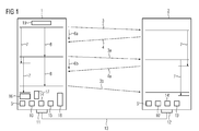
- a first communication device 1 is connected via a field bus 13 to a second communication device 2.
- the field bus 13 represents in detail a communication network.
- the second communication device 2 transmits a telegram 3 to the first communication device 1.
- the first communication device 1 and the second communication device 2 become also referred to as the first communication participant and second communication participant.
- the first communication user responds with a reply 4, which he sends to the second communication user.
- a time counter 5 is started in the second communication subscriber 2
- a first reaction time 6a is monitored by means of a monitoring means 16 ', the reaction time 6a being a period between the sending of the telegram 3 and the arrival of the answer 4 to the telegram 3 describes.
- the monitoring means 16 ' the elapsed time for the reaction time 6a is compared with the maximum maximum run time 7. Depending on this result, a communication error is reported.
- this signal state via the existing communication means, the state of the request signal 20 from the communication station 1 to the communication station 2 and assigned in communication subscriber 2 via an assignment means 17 'the memory means 5' either the first time value T01 or the second time value T02.
- a cycle time 8 symbolizes the runtime for the execution of a cyclically processed control program.
- the second communication subscriber is designed, for example, as a DP slave.
- the first communication station is designed as a programmable logic controller and represents the communication of a fail-safe host, whereby the DP slave is a fail-safe F-output device.
- the first communication subscriber is likewise configured with a time counter 5, a memory means 10, a transmission means 14, a reception means 15, an assignment means 17 and a monitoring means 16.
- the first communication participant and the second communication participants are similar in their construction, wherein in the FIG. 1 the corresponding components are each provided with a dash on the reference numeral. Since the first communication participant assumes the function of a host, he is further configured with a prediction means 18 and a determination means 19.
- the determining means 19 is configured to calculate a second time value from system information of the first communication subscriber. Furthermore, the first communication subscriber has prognosis means 18 for forecasting a change from a first operating state to a second operating state. With this forecasting means 18, the request signal 20 (see FIG. 2 ) can be generated.
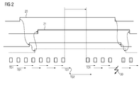
- FIG. 2 is the timing of the request signal 20 and the derived signals visible.
- a message signal 22 is generated in the first communication user and is transmitted via the interface 11 to the field bus 13 and transmitted to the second communication user.
- the acknowledgment signal 23 in turn triggers an enable signal 21.
- the enable signal 21 is in turn connected to the fieldbus 13 via the interface and ensures that a flag is set in the second communication station, which corresponds to a status that the second communication user may now work with an extended monitoring time.
- the time value is changed from T01 to T02 on the basis of the enable signal 21 in the memory means 10 '.
- the extended time value T02 results from the sum of the first time value T01 plus an additional time TZ.
- the marker Since the marker is set in the second communication participant, it may now come to a delay time 31 in the communication process.
- This delay time 31 occurs, for example, when a configuration change has to be made in the first communication user.
- the first communication user is a programmable logic controller
- a so-called “configuration change in run-time” could occur, ie the programmable logic controller is updated at runtime with a changed configuration. Since this more loads the programmable logic controller, it can no longer respond as usual to incoming telegrams in a guaranteed time. Therefore, a time value for a monitoring time is extended for such cases.
- This extension of monitoring times is preferably carried out only for non-critical operating conditions, for example for a steady state of the system or if the operator of the system can say that it is unlikely that unforeseen events will occur for the next time.
- the edge of the message signal 22 which in turn has the consequence that the acknowledgment signal 23 in the second communication subscriber goes back and thus the readiness for the extended response time in second communication participant is withdrawn. Since the acknowledgment signal 23 is withdrawn with a negative edge, the enable signal 21 is also withdrawn with a time delay.
- a communication fault 30 would result in the second communication user, configured as an output device, outputting the safe substitute values FV (instead of the process values) for his output values. Failsafe values).
Landscapes
- Engineering & Computer Science (AREA)
- Computer Networks & Wireless Communication (AREA)
- Signal Processing (AREA)
- Environmental & Geological Engineering (AREA)
- Selective Calling Equipment (AREA)
Priority Applications (1)
| Application Number | Priority Date | Filing Date | Title |
|---|---|---|---|
| EP09150889A EP2209258A1 (fr) | 2009-01-20 | 2009-01-20 | Procédé destiné au fonctionnement d'un réseau de communication et appareil de communication |
Applications Claiming Priority (1)
| Application Number | Priority Date | Filing Date | Title |
|---|---|---|---|
| EP09150889A EP2209258A1 (fr) | 2009-01-20 | 2009-01-20 | Procédé destiné au fonctionnement d'un réseau de communication et appareil de communication |
Publications (1)
| Publication Number | Publication Date |
|---|---|
| EP2209258A1 true EP2209258A1 (fr) | 2010-07-21 |
Family
ID=40578510
Family Applications (1)
| Application Number | Title | Priority Date | Filing Date |
|---|---|---|---|
| EP09150889A Ceased EP2209258A1 (fr) | 2009-01-20 | 2009-01-20 | Procédé destiné au fonctionnement d'un réseau de communication et appareil de communication |
Country Status (1)
| Country | Link |
|---|---|
| EP (1) | EP2209258A1 (fr) |
Cited By (1)
| Publication number | Priority date | Publication date | Assignee | Title |
|---|---|---|---|---|
| CN107168183A (zh) * | 2017-06-29 | 2017-09-15 | 三星电子(中国)研发中心 | 一种设备控制方法和装置 |
Citations (3)
| Publication number | Priority date | Publication date | Assignee | Title |
|---|---|---|---|---|
| US6983324B1 (en) | 2000-10-23 | 2006-01-03 | International Business Machines Corporation | Dynamic modification of cluster communication parameters in clustered computer system |
| WO2007009454A2 (fr) * | 2005-07-22 | 2007-01-25 | Ruppert Koch | Procede de detection de dysfonctionnements |
| US20070112954A1 (en) | 2005-11-15 | 2007-05-17 | Yahoo! Inc. | Efficiently detecting abnormal client termination |
-
2009
- 2009-01-20 EP EP09150889A patent/EP2209258A1/fr not_active Ceased
Patent Citations (3)
| Publication number | Priority date | Publication date | Assignee | Title |
|---|---|---|---|---|
| US6983324B1 (en) | 2000-10-23 | 2006-01-03 | International Business Machines Corporation | Dynamic modification of cluster communication parameters in clustered computer system |
| WO2007009454A2 (fr) * | 2005-07-22 | 2007-01-25 | Ruppert Koch | Procede de detection de dysfonctionnements |
| US20070112954A1 (en) | 2005-11-15 | 2007-05-17 | Yahoo! Inc. | Efficiently detecting abnormal client termination |
Cited By (1)
| Publication number | Priority date | Publication date | Assignee | Title |
|---|---|---|---|---|
| CN107168183A (zh) * | 2017-06-29 | 2017-09-15 | 三星电子(中国)研发中心 | 一种设备控制方法和装置 |
Similar Documents
| Publication | Publication Date | Title |
|---|---|---|
| EP2235861B1 (fr) | Procédé et dispositif de transmission de données dans un réseau | |
| DE19939567B4 (de) | Vorrichtung zum Steuern von sicherheitskritischen Prozessen | |
| DE102009042368B4 (de) | Steuerungssystem zum Steuern von sicherheitskritischen Prozessen | |
| EP1205052A1 (fr) | Procede pour le reglage d'une vitesse de transmission de donnees dans un systeme a bus de terrain | |
| WO2009040298A1 (fr) | Procédé de fonctionnement d'un système de bus et système de bus | |
| EP2538609A1 (fr) | Economie d'énergie dans un noeud de réseau d'un réseau d'automatisation | |
| EP3673621B1 (fr) | Procédé de transmission de données entre un dispositif de commande central et une pluralité d'appareils décentralisés et dispositifs correspondants | |
| EP1206868A2 (fr) | Procede de configuration d'un noeud sur et systeme de commande sur comportant un tel noeud | |
| DE102016000215A1 (de) | Numerisches Steuersystem mit Selbstrücksetzfunktion für ein internes Register mit serieller Kommunikationssignalüberwachung | |
| EP4012517A1 (fr) | Environnement d'exécution permettant d'exécuter un programme de commande axé sur les événements | |
| EP3570499B1 (fr) | Procédé d'identification de connexion fonctionnellement sûre | |
| EP2418580B1 (fr) | Procédé destiné au fonctionnement d'un réseau et réseau | |
| EP2778811A1 (fr) | Dispositif pour un système d'interface AS | |
| EP4300220B1 (fr) | Procédé de communication de sécurité et dispositif de communication | |
| DE102024103912A1 (de) | Fehlererkennungsverfahren | |
| EP2950176A1 (fr) | Procédé et composants d'automatisation destinés à la génération d'une information de changement d'état | |
| DE19940874A1 (de) | Verfahren zum Konfigurieren eines sicheren Busteilnehmers und sicheres Steuerungssystem mit einem solchen | |
| EP4524661B1 (fr) | Procédé de surveillance d'une liaison de communication | |
| EP4216004A2 (fr) | Dispositif de commande et procédé de commande d'une installation automatisée | |
| DE102010038484A1 (de) | Verfahren und Vorrichtung zum Steuern einer Anlage | |
| EP1267270B1 (fr) | Méthode de communication de données dans un système d'ordinateur | |
| DE102018221417B4 (de) | Fahrzeug mit einem Netzwerkverteiler zum Melden einer Störung in einem Kommunikationsnetzwerk | |
| DE102020207744A1 (de) | Verfahren zum Betreiben eines echtzeitbasierten Kommunikationssystems, Kommunikationssystem und Kommunikationseinheit | |
| EP3026514B1 (fr) | Installation d'automatisation et procédé de commande externe d'un algorithme d'autocontrôle dans un dispositif de sécurité décentralisé | |
| DE102012021888B4 (de) | Kommunikationsverfahren für verteilte sicherheitsgerichtete Automatisierungseinrichtungen |
Legal Events
| Date | Code | Title | Description |
|---|---|---|---|
| PUAI | Public reference made under article 153(3) epc to a published international application that has entered the european phase |
Free format text: ORIGINAL CODE: 0009012 |
|
| AK | Designated contracting states |
Kind code of ref document: A1 Designated state(s): AT BE BG CH CY CZ DE DK EE ES FI FR GB GR HR HU IE IS IT LI LT LU LV MC MK MT NL NO PL PT RO SE SI SK TR |
|
| AX | Request for extension of the european patent |
Extension state: AL BA RS |
|
| 17P | Request for examination filed |
Effective date: 20110118 |
|
| 17Q | First examination report despatched |
Effective date: 20110207 |
|
| AKX | Designation fees paid |
Designated state(s): DE FR GB IT |
|
| RAP1 | Party data changed (applicant data changed or rights of an application transferred) |
Owner name: SIEMENS AKTIENGESELLSCHAFT |
|
| STAA | Information on the status of an ep patent application or granted ep patent |
Free format text: STATUS: THE APPLICATION HAS BEEN REFUSED |
|
| 18R | Application refused |
Effective date: 20130414 |