EP2210137B1 - Câble de surveillance de fond de trou doté d'une couche absorbant l'hydrogène - Google Patents
Câble de surveillance de fond de trou doté d'une couche absorbant l'hydrogène Download PDFInfo
- Publication number
- EP2210137B1 EP2210137B1 EP08850027.7A EP08850027A EP2210137B1 EP 2210137 B1 EP2210137 B1 EP 2210137B1 EP 08850027 A EP08850027 A EP 08850027A EP 2210137 B1 EP2210137 B1 EP 2210137B1
- Authority
- EP
- European Patent Office
- Prior art keywords
- polymer layer
- layer
- fiber optic
- cable
- thermal expansion
- Prior art date
- Legal status (The legal status is an assumption and is not a legal conclusion. Google has not performed a legal analysis and makes no representation as to the accuracy of the status listed.)
- Not-in-force
Links
Images


Classifications
-
- G—PHYSICS
- G02—OPTICS
- G02B—OPTICAL ELEMENTS, SYSTEMS OR APPARATUS
- G02B6/00—Light guides; Structural details of arrangements comprising light guides and other optical elements, e.g. couplings
- G02B6/44—Mechanical structures for providing tensile strength and external protection for fibres, e.g. optical transmission cables
- G02B6/4401—Optical cables
- G02B6/4429—Means specially adapted for strengthening or protecting the cables
- G02B6/44382—Means specially adapted for strengthening or protecting the cables the means comprising hydrogen absorbing materials
-
- E—FIXED CONSTRUCTIONS
- E21—EARTH OR ROCK DRILLING; MINING
- E21B—EARTH OR ROCK DRILLING; OBTAINING OIL, GAS, WATER, SOLUBLE OR MELTABLE MATERIALS OR A SLURRY OF MINERALS FROM WELLS
- E21B47/00—Survey of boreholes or wells
- E21B47/06—Measuring temperature or pressure
-
- E—FIXED CONSTRUCTIONS
- E21—EARTH OR ROCK DRILLING; MINING
- E21B—EARTH OR ROCK DRILLING; OBTAINING OIL, GAS, WATER, SOLUBLE OR MELTABLE MATERIALS OR A SLURRY OF MINERALS FROM WELLS
- E21B47/00—Survey of boreholes or wells
- E21B47/12—Means for transmitting measuring-signals or control signals from the well to the surface, or from the surface to the well, e.g. for logging while drilling
- E21B47/13—Means for transmitting measuring-signals or control signals from the well to the surface, or from the surface to the well, e.g. for logging while drilling by electromagnetic energy, e.g. radio frequency
- E21B47/135—Means for transmitting measuring-signals or control signals from the well to the surface, or from the surface to the well, e.g. for logging while drilling by electromagnetic energy, e.g. radio frequency using light waves, e.g. infrared or ultraviolet waves
-
- G—PHYSICS
- G01—MEASURING; TESTING
- G01K—MEASURING TEMPERATURE; MEASURING QUANTITY OF HEAT; THERMALLY-SENSITIVE ELEMENTS NOT OTHERWISE PROVIDED FOR
- G01K1/00—Details of thermometers not specially adapted for particular types of thermometer
- G01K1/08—Protective devices, e.g. casings
- G01K1/10—Protective devices, e.g. casings for preventing chemical attack
-
- G—PHYSICS
- G01—MEASURING; TESTING
- G01K—MEASURING TEMPERATURE; MEASURING QUANTITY OF HEAT; THERMALLY-SENSITIVE ELEMENTS NOT OTHERWISE PROVIDED FOR
- G01K11/00—Measuring temperature based upon physical or chemical changes not covered by groups G01K3/00, G01K5/00, G01K7/00 or G01K9/00
- G01K11/32—Measuring temperature based upon physical or chemical changes not covered by groups G01K3/00, G01K5/00, G01K7/00 or G01K9/00 using changes in transmittance, scattering or luminescence in optical fibres
-
- G—PHYSICS
- G02—OPTICS
- G02B—OPTICAL ELEMENTS, SYSTEMS OR APPARATUS
- G02B6/00—Light guides; Structural details of arrangements comprising light guides and other optical elements, e.g. couplings
- G02B6/44—Mechanical structures for providing tensile strength and external protection for fibres, e.g. optical transmission cables
- G02B6/4401—Optical cables
- G02B6/4415—Cables for special applications
- G02B6/4416—Heterogeneous cables
Definitions
- Embodiments described relate to hydrocarbon monitoring cables for monitoring of downhole conditions in a hydrocarbon well.
- embodiments of hydrocarbon monitoring cables are described that are configured for placement and relatively continuous monitoring of the well over an extended period of time, perhaps between about 11 ⁇ 2 and 5 years.
- a variety of hydrocarbon applications involve the use of cables disposed within a hydrocarbon well.
- a hydrocarbon cable may be positioned within a well during hydrocarbon production from the well so as to monitor well conditions during the production.
- a fiber optic core may be present through the cable in order to obtain well condition information such as temperature.
- well condition information such as temperature.
- a temperature profile of the well may be acquired, with readings from each point along the fiber optic core.
- Such information may be employed to extrapolate production data useful in the production application. For example, estimates of flow-rate may be calculated by examination of temperature differentials across a temperature profile acquired by such a hydrocarbon monitoring cable.
- the cable When employing a hydrocarbon monitoring cable as noted above, the cable may be left in place along several thousand feet of the well and exposed to the environment of the hydrocarbon well for an extended period of time. For example, hydrocarbon production may take place over the course of about 11 ⁇ 2 to 5 years with an attempt to leave the cable in place for the duration. In this manner, real-time monitoring of well conditions may be employed. As such, the production application may be modified in accordance with changing conditions within the well.
- the fiber optic core is generally of a loop configuration, carrying a light signal downhole and providing a return path uphole for measurement and analysis at the well surface.
- the opportunity for the formation of such defects along the path of the fiber optic core is twofold from the perspective of the length of the cable.
- the core may be surrounded by a host of coatings, gels, and/or metal layers acting as shields.
- a carbon coating for example, may be particularly effective at shielding an underlying fiber optic core from hydrogen attack
- JP-A-1304408 describes an optical fiber cable which is resistant to hydrogen.
- the inner fiber optic core is shielded firstly by an hermetic coating of ScOxNy or amorphous carbon, with a protective coating on top of that.
- the protective coating is formed of one or more layers of, for example, thermoplastic resin.
- WO-A-2006/113322 discloses a fiber optic cable having a hydrogen barrier shield surrounding it.
- the judrogen barrier shield is in turn surrounded by an outer axial tube to act as an hydrostatic pressure boundary.
- shielding of the underlying fiber optic core may leave the overall profile of the monitoring cable of an impractical size, perhaps occluding the well itself to a significant degree. Furthermore, such shielding may also leave the fiber optic core susceptible to thermally induced defects therein. That is, even where a reduced profile may be achievable, for example, with employment of a thin carbon coating, the addition of this shielding layer introduces a new material for the cable with its own coefficient of thermal expansion. This coefficient of thermal expansion for the newly introduced shielding material may not match that of other material layers surrounding the shielding material, such as a conductor layer or outer polymer jacket.
- the fiber optic capacity of a conventional hydrocarbon monitoring cable of practical sizing will generally be rendered useless in a matter of months if left in place for downhole monitoring.
- the high pressure, high temperature, hydrogen environment of a typical hydrocarbon well ultimately renders the cable ineffective for continuous fiber optic monitoring of downhole conditions throughout production.
- a hydrocarbon monitoring cable is provided for positioning in the downhole environment of a well.
- the cable is defined in claim 1, and includes a fiber optic core with a carbon layer thereabout to provide shielding from exposure to defect inducing agents of the downhole environment, namely hydrogen.
- the carbon layer itself has a first coefficient of thermal expansion whereas an outer polymer layer around the carbon layer is of a second coefficient of thermal expansion.
- An intermediate polymer layer of a third coefficient of thermal expansion is disposed between the carbon layer and the outer polymer layer. The intermediate polymer layer is selected based on the first and second coefficients of thermal expansion so as avoid fiber optic defect causing thermal expansion from the downhole environment.
- the hydrocarbon monitoring cable may include a fiber optic core with an electrically conductive layer thereabout.
- the electrically conductive layer may be positively charged to repel a fiber optic defect causing agent of the environment (hydrogen).
- Embodiments are described with reference to certain hydrocarbon monitoring cables. Configurations of cables are described for long term placement and monitoring of well conditions within a hydrocarbon producing well. That said, a variety of configurations may be employed. Regardless, the particular embodiments described may include features for extending the useful life of a fiber optic core of the cable. This may be achieved in a number of ways, including by shielding, repelling or absorbing defect inducing agents away from the core. Additionally, the life of the core may be extended by reducing the effect of thermal mismatch between outer layers surrounding the core by the addition of an intermediate layer between such outer layers.
- the intermediate layer may be of a soft polymer having a coefficient of thermal expansion selected based on coefficients of thermal expansion of the outer layers as detailed herein below.
- a hydrocarbon monitoring cable 100 is depicted within a hydrocarbon well 180.
- the well 180 may include a casing 150 adjacent a well wall 170 and traversing a geologic formation 190.
- hydrocarbons may be produced from the formation 190 through the well 180.
- the hydrocarbon monitoring cable 100 may be coupled to surface equipment and employed to monitor the conditions of the well 180 in real-time. Information obtained from monitoring of the well 180 in this manner may then be employed dynamically to modify a well production application as needed, for example, in accordance with changing well conditions over time.
- a fiber optic core 125 of the cable 100 may be employed in acquiring the above-noted well condition information.
- a dynamic profile of well conditions may be built from readings along each point of the fiber optic core 125.
- Temperature information in particular may be acquired and employed in this manner. For example, in one embodiment, estimates of flow-rate may be calculated by examination of temperature differentials across a temperature profile constructed by employment of such a hydrocarbon monitoring cable 100.
- the hydrocarbon monitoring cable 100 may be disposed through the well 180 to a depth of several thousand feet.
- the cable 100 may be left in position in this manner for an extended period of time, for example for the duration of the hydrocarbon production application. As indicated, this may result in the cable 100 being exposed to the environment of the hydrocarbon well 180 for between about 11 ⁇ 2 to about 5 years as the hydrocarbons are extracted from the formation 190.
- the hydrocarbon monitoring cable 100, and in particular, its fiber optic core 125 may be exposed to pressure and temperature extremes as well as an abundance of hydrogen ions 140 or other defect causing agents. Indeed, the degree of these extremes and abundance of such agents may increase as the depth of the well 180 increases. Nevertheless, as described below, measures may be taken to help ensure the cable 100 and core 125 maintain adequate functionality for the monitoring period of up to about 5 years in spite of exposure to the indicated harsh downhole conditions.
- the monitoring capacity of the hydrocarbon monitoring cable 100 may be extended to about 5 years as indicated due to built-in features thereof, keeping the rate of attenuation of hydrogen ions 140 to the fiber optic core 125 to a minimum.
- the fiber optic core 125 may be about 10km in length with a 100dBm tolerance. That is, the core 125 may remain functional for monitoring purposes until attenuation reaches a level such that the communicative capacity of the core 125 is reduced by about 100dBm.
- embodiments detailed below may include shielding that slows the rate of attenuation of hydrogen ions 140 to the core 125 such that a reduction in communicative capacity of less than about 20dBm per year occurs (e.g. helping to ensure a 5 year useful life of the cable 100).
- the fiber optic core 125 may be surrounded by a carbon layer 260 or coating configured to shield hydrogen ions 140 away from an inner core 220 and cladding 240 thereof. In this manner, the rate of attenuation of hydrogen into the core 125 may be reduced as indicated above. As such, the reaction of glass material of the core 125 with hydrogen ions 140 to form damaging hydroxyl groups may be minimized and delayed, thereby extending the life of the hydrocarbon monitoring cable 100.
- an outer polymer layer 280 or jacket may be provided to the hydrocarbon monitoring cable 100.
- the carbon layer 260 may be configured with a focus on shielding the underlying core 125 from direct contact with hydrogen ions 140 or other defect inducing agents with the potential for attenuation into the cable 100.
- the outer polymer layer 280 may be configured in light of its more direct exposure to the overall environment of the well 180. As such, durability, moisture resistance, and other tailored characteristics of the outer polymer layer 280 may differ significantly from those of the carbon layer 260. As a result, the coefficient of thermal expansion of the outer polymer layer 280 may differ substantially from that of the carbon layer 260.
- the above described difference in coefficients of thermal expansion may be significant given the temperature extremes likely to be encountered by the hydrocarbon monitoring cable 100 within the depths of the well 180. That is, the difference in the thermally expansive nature from one layer (e.g. 260) to the next (e.g. 280) may be quite pronounced as a result of the downhole exposure to temperature extremes. Nevertheless, as detailed below, the hydrocarbon monitoring cable 100 is equipped with an intermediate polymer layer 200 configured to minimize the stress of such differing coefficients of thermal expansion relative to the underlying fiber optic core 125. As such, thermally induced defects or microbending within the core 125 may be minimized and the life of the cable 100 extended.
- the intermediate polymer layer 200 is shown disposed between the outer polymer layer 280 and the carbon layer 260.
- the intermediate polymer layer 200 may be of a generally softer polymer than that of the outer polymer layer 280.
- the intermediate polymer layer 200 may also include a coefficient of thermal expansion chosen in light of the differing coefficients of thermal expansion of the adjacent layers 260, 280.
- the intermediate polymer layer 200 is of a coefficient of thermal expansion that is between that of the adjacent layers 260, 280.
- the intermediate polymer layer 200 may be able to accommodate expansion of the adjacent layers 260, 280 without significant resistance thereto. As a result, the stress of expansion of one adjacent layer (e.g. 280) is not significantly translated across the intermediate polymer layer 200 to the other adjacent layer (e.g. 260).
- the formation of cracks within the fiber optic core 125 brought on by the stress of nearby material layers 260, 280 of substantially differing thermal character may be avoided. That is, by separating the outer polymer layer 280 from the carbon layer 260 with a thermally cooperative medium therebetween (i.e. the intermediate polymer layer 200), mechanical stress due to the differing thermally expansive characteristics of the layers 260, 280, may be substantially eliminated. As such, the fiber optic core 125 may be spared exposure to such mechanical stress, thereby extending the useful life of the cable 100.
- the carbon layer 260 is configured to shield the fiber optic core 125 to reduce direct contact with hydrogen ions 140.
- the carbon layer 260 is of a carbon based material with a predetermined coefficient of thermal expansion, perhaps less than about 10 ppm per degree Celsius.
- the outer polymer layer 280 may be of a hard polymer with a coefficient of thermal expansion greater than that of the carbon layer 260, perhaps exceeding about 30 ppm per degree Celsius.
- the intermediate polymer layer 200 may thus be of a soft polymer to accommodate thermal expansion of both the carbon layer 260 and the outer polymer layer 280 without translating significant expansive forces from one layer to the other as noted above.
- a variety of materials may be employed for the intermediate and outer polymer layers 200, 280.
- soft and hard versions of the same polymer type may be selected for the layers 200, 280.
- the intermediate polymer layer 200 may be a soft polyimide whereas the outer polymer layer 280 may be of a hard polyimide.
- the intermediate polymer layer 200 may be a soft acrylic whereas the outer polymer layer 280 may be of a hard acrylic.
- Other soft - hard polymer combinations may include soft and hard versions of ethylene propylene diene monomer rubber as well as soft and hard versions of a polyolefin.
- the intermediate polymer layer 200 may be a soft silicone and the outer polymer layer 280 a fluoroplastic such as polyoxymethylene.
- the soft polymer of the intermediate polymer layer 200 may be a fluoroelastomer, a perfluoroelastomer, and a perfluoroether.
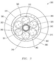
- a hydrocarbon monitoring cable 300 may include a layer of conductors 310, 315 for transferring power and electronic signals, for example, resistivity measurements therethrough.
- the conductors 310, 315 may also serve as reinforcing strength members for the cable 300, perhaps being strands helically wound about the fiber optic core 325 (as in the case of the depicted advancing conductors 310).
- the conductors 310, 315 are of copper, copper coated steel, and/or nickel plated to withstand the corrosive downhole environment.
- the conductors 310, 315 are in the form of advancing conductors 310 and a return conductor ring 315 to provide electronic pathways through the cable 300.
- Such a configuration may include conductors 310, 315 contained by an external jacket 390 and suspended or isolated by a suspending polymer layer 302. Additionally, all of these features 310, 315, 302, 390, may be provided about an underlying construction of an outer polymer layer 380, intermediate polymer layer 301, carbon layer 360 and fiber optic core 325 similar to the embodiment of Fig. 2 .
- the conductors 310, 315 may be of a material having its own particular coefficient of thermal expansion which may differ significantly from the thermal coefficients of other material layers 360, 301, 380 of the cable 300.
- the conductors 310, 315 may be of copper or copper coated steel whereas the material layers 360, 301, 380 may be of polymer and carbon materials as detailed above with reference to the embodiment of Fig. 2 .
- the suspending polymer layer 302 may be disposed adjacently about the conductors 310, 315.
- the suspending polymer layer 302 may be of a soft polymer and of a coefficient of thermal expansion selected based on that of an outer polymer layer 380 about the core 325 as well as that of the conductors 310, 315.
- the suspending polymer layer 302 may be a soft polymer of a material type described with reference to the embodiment of Fig. 2 .
- a reduction in the amount of mechanical stress translatable toward the fiber optic core 325 may be realized thereby also reducing mechanical stress and microbending defects within the core 325.
- a reduction in mechanical stress due to differing thermal characteristics between the conductors 310, 315 and the outer polymer layer 380 may be achieved.
- a further reduction in mechanical stress may again be achieved by the inclusion of an intermediate polymer layer 301 between an outer polymer layer 380 and an underlying carbon layer 360 on the fiber optic core 325. That is, as with the embodiment of Fig. 2 , the intermediate polymer layer 301 may serve as a medium between the carbon layer 360 and the outer polymer layer 380 thereby minimizing the effects of differing characteristics of thermal expansion therebetween. As a result, mechanical stress on the fiber optic core 325 may again be reduced.
- the intermediate polymer layer 301 and the outer polymer layer 380 may be of material types described above, in the embodiment of Fig. 2 , for the intermediate polymer layer 200 and the outer polymer layer 280, respectively.
- the suspending polymer layer 302 may be of the same soft polymer material as that of the intermediate polymer layer 301.
- the fiber optic core 325 is shielded by a carbon layer 360 with a soft intermediate polymer layer 301 thereabout.
- a hard outer polymer layer 380 of the same polymer type as that of the intermediate polymer layer 301 is provided thereabout.
- the same soft polymer employed for the intermediate polymer layer 301 is similarly provided in the form of the suspending polymer layer 302 within which the conductors 310, 315 are isolated. Due to the soft mediums of the suspending polymer layer 302 and the intermediate polymer layer 301, a reduction in the formation of defects in the fiber optic core 325 due to differing thermal characteristics in material layers 360, 380 and conductors 310, 315 thereabout may be achieved.
- a further reduction in defects in the fiber optic core 325 may be achieved by employing conductors 310, 315 that are positively charged (as indicated by positive charges 340). That is, as indicated above, a hydrocarbon monitoring cable 300 may be equipped with conductors 310, 315 for carrying electronic signal therethrough. These conductors 310, 315 may be equipped with positive charges 340 by conventional means, for example, at the time of manufacture. In this manner, hydrogen ions 140 such as those depicted in Fig. 1 may be repelled away from the hydrocarbon monitoring cable 100. That is, the cable 100 may be equipped to repel hydrogen ions 140, at least to the extent of the amount of positive charge held by the conductors 310, 315.
- positive charge may be provided to selected conductors 310, 315 such as the advancing conductors 310 or the return conductor 315 alone.
- all conductors 310, 315 may be equipped with positive charge 340 in order to maximize the amount of shielding available to the fiber optic core 325 from positively charged conductors 310, 315.
- the size of the conductors 310, 315 may be determined in part based on the amount of charge to be accommodated.
- the size and materials of the adjacently disposed electrically isolating layers i.e. the external jacket 390 and the suspending polymer layer 302
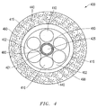
- a layer of the cable 400 may be hydrogen absorbing in nature, for example through the use of glass or carbon.
- a polymer layer such as the external jacket 490, may be loaded with hydrogen absorbing agent 440. That is, as opposed to positive charges 340 as depicted in Fig. 3 , a hydrogen absorbing agent 440 such as carbon nanotubes and/or carbon or glass fibers may be disbursed throughout the external jacket 490 or other polymer layer external to the fiber optic core 425. In this manner, hydrogen ions 140, such as those depicted in Fig.
- the cable 400 may be equipped with conductors 410, 415 which may be charged in order to repel hydrogen ions 140 once the hydrogen absorbing agent 440 is saturated.
- the jacket 490 as well as the underlying suspending polymer layer 402, outer polymer layer 480, and intermediate polymer layer 401 as described below, may each accommodate hydrogen absorbing agent 440.
- the cable 400 of Fig. 4 may again include a fiber optic core 425 that is protected by a carbon layer 460. Additionally, an intermediate polymer layer 401 may be provided interiorly adjacent an outer polymer layer 480 as a means of reducing the occurrence of microbendings within the core 425 due to mechanical stresses resulting from mismatched coefficients of thermal expansion as described above. As also detailed above, the cable 400 may be equipped with conductors 410, 415. In the embodiment shown, the conductors 410, 415 may be charged as detailed above in order to shield the underlying core 425 from exposure to hydrogen ions 140 (as shown in Fig. 1 ).
- Embodiments of hydrocarbon monitoring cables 100, 300, 400 may employ additional features to those detailed above in order to increase the useful life thereof.
- a tubular or ringed lead jacket may be employed in place of, or in addition to, the return conductor 315, 415 in order to provide additional hydrogen shielding.
- the outermost layer of the cable 100, 300, 400 may include a steel based alloy incorporating iron, nickel-chromium, or other corrosion inhibitors relative to a downhole environment.
- a hydrocarbon monitoring cable 500 is employed within a productive well 575 for an extended duration without need for replacement.
- surface equipment 525 is positioned at an oilfield 550 above the well 575 and the cable 500 positioned therethrough as a hydrocarbon is extracted through formation layers 555, 560.
- the cable 500 may incorporate a fiber optic core assembly and yet, remain in place for the substantial duration of the hydrocarbon production, without need for replacement. That is, due to thermal compatibility and hydrogen shielding features detailed above, the fiber optic core of the hydrocarbon monitoring cable 500 may remain viable for an extended period of time, likely to cover the duration of the hydrocarbon production (e.g. up to about 5 years).
- Embodiments of a hydrocarbon monitoring cable as described above include features for delaying the rate of attenuation of defect causing agents into the fiber optic core.
- optical imperfections within the core are kept to a minimum during monitoring of a production application with the cable.
- the integrity of fiber optic communication is maintained allowing measurements, analysis, and production itself to proceed without interruption for cable replacement.
- this may be achieved in a manner that avoids the use of a high profile gel and metal layer configurations that tend to affect the available diameter of the well itself.
- features of the cable may be layered in such a manner so as to substantially avoid thermally induced defects within the core.
Landscapes
- Physics & Mathematics (AREA)
- Engineering & Computer Science (AREA)
- Mining & Mineral Resources (AREA)
- Geology (AREA)
- Life Sciences & Earth Sciences (AREA)
- Remote Sensing (AREA)
- General Physics & Mathematics (AREA)
- General Life Sciences & Earth Sciences (AREA)
- Fluid Mechanics (AREA)
- Environmental & Geological Engineering (AREA)
- Geochemistry & Mineralogy (AREA)
- Geophysics (AREA)
- Electromagnetism (AREA)
- Optics & Photonics (AREA)
- Testing Relating To Insulation (AREA)
- Communication Cables (AREA)
- Investigating Or Analyzing Materials By The Use Of Electric Means (AREA)
Claims (9)
- Câble de surveillance d'hydrocarbure (400) destiné à être positionné dans un environnement de fond de trou (180), le câble de surveillance d'hydrocarbure (400) comprenant :un ensemble formant fibre optique comprenant un noyau de fibre optique (425) ;une couche de carbone (460) qui est disposée autour dudit noyau de fibre optique (425) en vue de fournir une protection contre l'exposition à l'hydrogène (140) à l'intérieur de l'environnement de fond de trou (180), ladite couche de carbone (460) étant dotée d'un premier coefficient de dilatation thermique ;une couche de polymère extérieure (480) qui est disposée autour de ladite couche de carbone (460) et qui est dotée d'un deuxième coefficient de dilatation thermique ; etune couche de polymère intermédiaire (401) qui est disposée entre ladite couche de carbone (460) et ladite couche de polymère extérieure (480), ladite couche de polymère intermédiaire (401) étant dotée d'un troisième coefficient de dilatation thermique qui est choisi en se basant sur les premier et deuxième coefficients de dilatation thermique, ladite couche de polymère intermédiaire (401) et ladite couche de polymère extérieure (480) comprenant un polymère du même type ;une couche absorbante à base de polymère (490) qui est disposée autour dudit ensemble formant fibre optique en vue d'absorber l'hydrogène (140), la couche absorbante (490) comprenant un agent absorbant l'hydrogène (440) qui est disposé dans celle-ci ; etune enveloppe de polymère extérieure qui est disposée autour dudit ensemble formant fibre optique et de ladite couche absorbante à base de polymère (490).
- Câble de surveillance d'hydrocarbure selon la revendication 1, dans lequel ledit agent absorbant (440) comprend l'un des éléments parmi le verre, une fibre de carbone et des nanotubes de carbone.
- Câble de surveillance d'hydrocarbure selon la revendication 1, dans lequel ledit noyau de fibre optique (425) est conçu de manière à relayer des informations relatives à la température.
- Câble de surveillance d'hydrocarbure selon la revendication 1, dans lequel le coefficient de dilatation thermique de ladite couche de carbone (460) est inférieur à environ 10 ppm/°C et le coefficient de dilatation thermique de ladite couche de polymère extérieure (480) est supérieur à environ 30 ppm/°C.
- Câble de surveillance d'hydrocarbure selon la revendication 4, dans lequel le coefficient de dilatation thermique de ladite couche de polymère intermédiaire (401) est entre environ 10 ppm/°C et environ 30 ppm/°C.
- Câble de surveillance d'hydrocarbure selon la revendication 1, dans lequel le coefficient de dilatation thermique de la couche de polymère intermédiaire (401) est inférieur au coefficient de dilatation thermique de la couche de polymère extérieure (480) et supérieur au coefficient de dilatation thermique de la couche de carbone (460) .
- Câble de surveillance d'hydrocarbure selon la revendication 1, dans lequel ladite couche de polymère intermédiaire (401) est plus molle que ladite couche de polymère extérieure (480).
- Câble de surveillance d'hydrocarbure selon la revendication 1, dans lequel le polymère est l'un des éléments parmi un polyimide, un acrylique, un éthylène, une polyoléfine, et un caoutchouc monomère diénique éthylène-propylène.
- Câble de surveillance d'hydrocarbure selon la revendication 1, comprenant en outre :une couche électroconductrice qui est disposée entre ledit ensemble formant fibre optique et ladite enveloppe de polymère extérieure.
Applications Claiming Priority (2)
| Application Number | Priority Date | Filing Date | Title |
|---|---|---|---|
| US11/938,395 US7769251B2 (en) | 2007-11-12 | 2007-11-12 | Hydrocarbon monitoring cable with an absorbing layer |
| PCT/IB2008/054653 WO2009063369A1 (fr) | 2007-11-12 | 2008-11-06 | Câble de surveillance de fond de trou doté d'une couche absorbant l'hydrogène |
Publications (2)
| Publication Number | Publication Date |
|---|---|
| EP2210137A1 EP2210137A1 (fr) | 2010-07-28 |
| EP2210137B1 true EP2210137B1 (fr) | 2016-05-11 |
Family
ID=40103109
Family Applications (1)
| Application Number | Title | Priority Date | Filing Date |
|---|---|---|---|
| EP08850027.7A Not-in-force EP2210137B1 (fr) | 2007-11-12 | 2008-11-06 | Câble de surveillance de fond de trou doté d'une couche absorbant l'hydrogène |
Country Status (5)
| Country | Link |
|---|---|
| US (1) | US7769251B2 (fr) |
| EP (1) | EP2210137B1 (fr) |
| CN (2) | CN101435901B (fr) |
| MX (1) | MX2010005182A (fr) |
| WO (1) | WO2009063369A1 (fr) |
Cited By (1)
| Publication number | Priority date | Publication date | Assignee | Title |
|---|---|---|---|---|
| RU2660753C1 (ru) * | 2017-07-25 | 2018-07-09 | Юрий Александрович Попов | Термометрическая коса (термокоса) |
Families Citing this family (12)
| Publication number | Priority date | Publication date | Assignee | Title |
|---|---|---|---|---|
| US7769251B2 (en) * | 2007-11-12 | 2010-08-03 | Schlumberger Technology Corporation | Hydrocarbon monitoring cable with an absorbing layer |
| US8369671B2 (en) * | 2010-02-26 | 2013-02-05 | General Electric Company | Hermetically sealed fiber sensing cable |
| US8942527B2 (en) * | 2011-03-22 | 2015-01-27 | Baker Hughes Incorporated | Extended temperature fiber optic cable design |
| US20140311758A1 (en) * | 2011-11-29 | 2014-10-23 | Schlumberger Technology Corporation | Continuously Bonded Small-Diameter Cable With Electrical Return On Outer Wires |
| US20150040288A1 (en) | 2013-08-06 | 2015-02-12 | Wilson Sporting Goods Co. | Sports glove |
| CN104021837B (zh) * | 2014-05-31 | 2017-12-26 | 西安交通大学 | 一种非金属轻型导电线及其方法和应用产品 |
| WO2015188082A1 (fr) * | 2014-06-05 | 2015-12-10 | Weatherford Technology Holdings, Llc | Mesure de profondeur de câble de transport de fond de trou |
| US10808499B2 (en) | 2015-11-18 | 2020-10-20 | Board Of Regents, The University Of Texas System | Hydrocarbon detection in oil and gas wells using fiber optic sensing cables |
| US11287590B2 (en) * | 2017-06-12 | 2022-03-29 | Corning Research & Development Corporation | In-road interface protected cable |
| WO2021145933A1 (fr) * | 2020-01-17 | 2021-07-22 | Landmark Graphics Corporation | Évaluation continue d'éléments de puits à l'aide de fibres optiques |
| CN115691897A (zh) * | 2022-10-25 | 2023-02-03 | 长江大学 | 一种用于井下永置使用的光电复合缆及光电复合缆组件 |
| WO2024159062A1 (fr) * | 2023-01-27 | 2024-08-02 | Schlumberger Technology Corporation | Câble à fibre optique |
Family Cites Families (17)
| Publication number | Priority date | Publication date | Assignee | Title |
|---|---|---|---|---|
| IT1184428B (it) * | 1985-04-12 | 1987-10-28 | Pirelli Cavi Spa | Composizione idrogeno assorbente per cavi e elettrici,cavi a fibre ottiche e loro componenti incorporanti detta composizione |
| JPH01304408A (ja) | 1988-06-02 | 1989-12-08 | Furukawa Electric Co Ltd:The | 光フアイバケーブル |
| JP3282640B2 (ja) * | 1993-01-27 | 2002-05-20 | 日本電信電話株式会社 | 海底光ケーブル |
| IT1264902B1 (it) * | 1993-06-29 | 1996-10-17 | Pirelli Cavi Spa | Composizione idrogeno-assorbente per cavi a fibre ottiche e cavo a fibre ottiche includente la suddetta composizione |
| US5892176A (en) | 1996-11-05 | 1999-04-06 | Phillip E. Pruett | Smooth surfaced fiber optic logging cable for well bores |
| US6404961B1 (en) * | 1998-07-23 | 2002-06-11 | Weatherford/Lamb, Inc. | Optical fiber cable having fiber in metal tube core with outer protective layer |
| WO2001025830A2 (fr) * | 1999-09-16 | 2001-04-12 | Corning Cable Systems Llc | Cable plat |
| US6813421B2 (en) * | 2001-12-26 | 2004-11-02 | Corning Cable Systems Llc | Fiber optic cable having a ripcord |
| WO2004040348A1 (fr) * | 2002-10-28 | 2004-05-13 | Judd Wire, Inc. | Cable a fibres optiques presentant une meilleure stabilite dimensionnelle |
| US20040109652A1 (en) | 2002-12-04 | 2004-06-10 | Alcatel | Fiber optic cables with a hydrogen absorbing material |
| US20060153508A1 (en) * | 2003-01-15 | 2006-07-13 | Sabeus Photonics, Inc., Corporation | System and method for deploying an optical fiber in a well |
| US7024081B2 (en) * | 2003-04-24 | 2006-04-04 | Weatherford/Lamb, Inc. | Fiber optic cable for use in harsh environments |
| US6907170B1 (en) * | 2004-07-22 | 2005-06-14 | Halliburton Energy Services, Inc. | Hydrogen diffusion delay barrier for fiber optic cables used in hostile environments |
| US7218820B2 (en) | 2004-07-22 | 2007-05-15 | Welldynamics, Inc. | Method and system for providing a hydrogen diffusion barrier for fiber optic cables used in hostile environments |
| US7920765B2 (en) * | 2005-06-09 | 2011-04-05 | Schlumberger Technology Corporation | Ruggedized optical fibers for wellbore electrical cables |
| GB0524838D0 (en) | 2005-12-06 | 2006-01-11 | Sensornet Ltd | Sensing system using optical fiber suited to high temperatures |
| US7769251B2 (en) * | 2007-11-12 | 2010-08-03 | Schlumberger Technology Corporation | Hydrocarbon monitoring cable with an absorbing layer |
-
2007
- 2007-11-12 US US11/938,395 patent/US7769251B2/en active Active
-
2008
- 2008-03-03 CN CN2008100821012A patent/CN101435901B/zh not_active Expired - Fee Related
- 2008-03-03 CN CNU2008200072090U patent/CN201155326Y/zh not_active Expired - Lifetime
- 2008-11-06 EP EP08850027.7A patent/EP2210137B1/fr not_active Not-in-force
- 2008-11-06 MX MX2010005182A patent/MX2010005182A/es active IP Right Grant
- 2008-11-06 WO PCT/IB2008/054653 patent/WO2009063369A1/fr not_active Ceased
Non-Patent Citations (1)
| Title |
|---|
| None * |
Cited By (1)
| Publication number | Priority date | Publication date | Assignee | Title |
|---|---|---|---|---|
| RU2660753C1 (ru) * | 2017-07-25 | 2018-07-09 | Юрий Александрович Попов | Термометрическая коса (термокоса) |
Also Published As
| Publication number | Publication date |
|---|---|
| WO2009063369A1 (fr) | 2009-05-22 |
| US20090123119A1 (en) | 2009-05-14 |
| CN101435901B (zh) | 2012-08-08 |
| CN101435901A (zh) | 2009-05-20 |
| EP2210137A1 (fr) | 2010-07-28 |
| US7769251B2 (en) | 2010-08-03 |
| CN201155326Y (zh) | 2008-11-26 |
| MX2010005182A (es) | 2010-06-01 |
Similar Documents
| Publication | Publication Date | Title |
|---|---|---|
| EP2210137B1 (fr) | Câble de surveillance de fond de trou doté d'une couche absorbant l'hydrogène | |
| US7496258B1 (en) | Hydrocarbon monitoring cable | |
| EP3398195B1 (fr) | Câble de fond de trou à diamètre réduit | |
| US5892176A (en) | Smooth surfaced fiber optic logging cable for well bores | |
| AU2012272590B2 (en) | Fiber-optic monitoring cable | |
| CA2933417C (fr) | Appareil pour detecter des signaux acoustiques dans un logement | |
| CN201196694Y (zh) | 具有改进疲劳寿命的弯曲不敏感性的光-电电缆 | |
| US9529169B2 (en) | Logging cable | |
| EA010402B1 (ru) | Усовершенствованные электрические кабели ствола скважины | |
| US9523832B2 (en) | High temperature, zero fiber strain, fiber optic cable | |
| BR102013026460A2 (pt) | Aparelho para corpo de tubo flexível e seu método de produção | |
| CA2509810A1 (fr) | Systeme et procede pour deployer une fibre optique dans un puits | |
| US20030169179A1 (en) | Downhole data transmisssion line | |
| US20090067776A1 (en) | Optical fibers | |
| CN114026658A (zh) | 机械响应性光纤线组件 | |
| CN119132714B (zh) | 脐带缆及脐带缆打孔方法 | |
| NO346692B1 (en) | A cable assembly | |
| CN103814321B (zh) | 光纤缆线 | |
| NL2033621B1 (en) | Permanent monitoring electro-optic down-hole cable and electro- optic cable assembly | |
| CN114600022A (zh) | 光缆、光缆监测系统以及井监测方法 | |
| RU2775375C1 (ru) | Оптический сенсорный кабель | |
| RU2775375C9 (ru) | Оптический сенсорный кабель |
Legal Events
| Date | Code | Title | Description |
|---|---|---|---|
| PUAI | Public reference made under article 153(3) epc to a published international application that has entered the european phase |
Free format text: ORIGINAL CODE: 0009012 |
|
| 17P | Request for examination filed |
Effective date: 20100614 |
|
| AK | Designated contracting states |
Kind code of ref document: A1 Designated state(s): AT BE BG CH CY CZ DE DK EE ES FI FR GB GR HR HU IE IS IT LI LT LU LV MC MT NL NO PL PT RO SE SI SK TR |
|
| AX | Request for extension of the european patent |
Extension state: AL BA MK RS |
|
| 17Q | First examination report despatched |
Effective date: 20101201 |
|
| DAX | Request for extension of the european patent (deleted) | ||
| GRAP | Despatch of communication of intention to grant a patent |
Free format text: ORIGINAL CODE: EPIDOSNIGR1 |
|
| RIC1 | Information provided on ipc code assigned before grant |
Ipc: G01K 1/10 20060101ALI20160121BHEP Ipc: E21B 47/12 20120101ALI20160121BHEP Ipc: G01K 11/32 20060101ALI20160121BHEP Ipc: G02B 6/44 20060101AFI20160121BHEP Ipc: E21B 47/06 20120101ALI20160121BHEP |
|
| INTG | Intention to grant announced |
Effective date: 20160204 |
|
| GRAS | Grant fee paid |
Free format text: ORIGINAL CODE: EPIDOSNIGR3 |
|
| GRAA | (expected) grant |
Free format text: ORIGINAL CODE: 0009210 |
|
| AK | Designated contracting states |
Kind code of ref document: B1 Designated state(s): AT BE BG CH CY CZ DE DK EE ES FI FR GB GR HR HU IE IS IT LI LT LU LV MC MT NL NO PL PT RO SE SI SK TR |
|
| REG | Reference to a national code |
Ref country code: GB Ref legal event code: FG4D |
|
| REG | Reference to a national code |
Ref country code: CH Ref legal event code: EP |
|
| REG | Reference to a national code |
Ref country code: AT Ref legal event code: REF Ref document number: 799103 Country of ref document: AT Kind code of ref document: T Effective date: 20160515 |
|
| REG | Reference to a national code |
Ref country code: IE Ref legal event code: FG4D |
|
| REG | Reference to a national code |
Ref country code: DE Ref legal event code: R096 Ref document number: 602008044235 Country of ref document: DE |
|
| REG | Reference to a national code |
Ref country code: NO Ref legal event code: T2 Effective date: 20160511 |
|
| REG | Reference to a national code |
Ref country code: LT Ref legal event code: MG4D |
|
| REG | Reference to a national code |
Ref country code: NL Ref legal event code: MP Effective date: 20160511 |
|
| PG25 | Lapsed in a contracting state [announced via postgrant information from national office to epo] |
Ref country code: FI Free format text: LAPSE BECAUSE OF FAILURE TO SUBMIT A TRANSLATION OF THE DESCRIPTION OR TO PAY THE FEE WITHIN THE PRESCRIBED TIME-LIMIT Effective date: 20160511 Ref country code: NL Free format text: LAPSE BECAUSE OF FAILURE TO SUBMIT A TRANSLATION OF THE DESCRIPTION OR TO PAY THE FEE WITHIN THE PRESCRIBED TIME-LIMIT Effective date: 20160511 Ref country code: LT Free format text: LAPSE BECAUSE OF FAILURE TO SUBMIT A TRANSLATION OF THE DESCRIPTION OR TO PAY THE FEE WITHIN THE PRESCRIBED TIME-LIMIT Effective date: 20160511 |
|
| REG | Reference to a national code |
Ref country code: AT Ref legal event code: MK05 Ref document number: 799103 Country of ref document: AT Kind code of ref document: T Effective date: 20160511 |
|
| PG25 | Lapsed in a contracting state [announced via postgrant information from national office to epo] |
Ref country code: HR Free format text: LAPSE BECAUSE OF FAILURE TO SUBMIT A TRANSLATION OF THE DESCRIPTION OR TO PAY THE FEE WITHIN THE PRESCRIBED TIME-LIMIT Effective date: 20160511 Ref country code: PT Free format text: LAPSE BECAUSE OF FAILURE TO SUBMIT A TRANSLATION OF THE DESCRIPTION OR TO PAY THE FEE WITHIN THE PRESCRIBED TIME-LIMIT Effective date: 20160912 Ref country code: SE Free format text: LAPSE BECAUSE OF FAILURE TO SUBMIT A TRANSLATION OF THE DESCRIPTION OR TO PAY THE FEE WITHIN THE PRESCRIBED TIME-LIMIT Effective date: 20160511 Ref country code: ES Free format text: LAPSE BECAUSE OF FAILURE TO SUBMIT A TRANSLATION OF THE DESCRIPTION OR TO PAY THE FEE WITHIN THE PRESCRIBED TIME-LIMIT Effective date: 20160511 Ref country code: LV Free format text: LAPSE BECAUSE OF FAILURE TO SUBMIT A TRANSLATION OF THE DESCRIPTION OR TO PAY THE FEE WITHIN THE PRESCRIBED TIME-LIMIT Effective date: 20160511 Ref country code: GR Free format text: LAPSE BECAUSE OF FAILURE TO SUBMIT A TRANSLATION OF THE DESCRIPTION OR TO PAY THE FEE WITHIN THE PRESCRIBED TIME-LIMIT Effective date: 20160812 |
|
| PG25 | Lapsed in a contracting state [announced via postgrant information from national office to epo] |
Ref country code: IT Free format text: LAPSE BECAUSE OF FAILURE TO SUBMIT A TRANSLATION OF THE DESCRIPTION OR TO PAY THE FEE WITHIN THE PRESCRIBED TIME-LIMIT Effective date: 20160511 |
|
| PG25 | Lapsed in a contracting state [announced via postgrant information from national office to epo] |
Ref country code: DK Free format text: LAPSE BECAUSE OF FAILURE TO SUBMIT A TRANSLATION OF THE DESCRIPTION OR TO PAY THE FEE WITHIN THE PRESCRIBED TIME-LIMIT Effective date: 20160511 Ref country code: CZ Free format text: LAPSE BECAUSE OF FAILURE TO SUBMIT A TRANSLATION OF THE DESCRIPTION OR TO PAY THE FEE WITHIN THE PRESCRIBED TIME-LIMIT Effective date: 20160511 Ref country code: EE Free format text: LAPSE BECAUSE OF FAILURE TO SUBMIT A TRANSLATION OF THE DESCRIPTION OR TO PAY THE FEE WITHIN THE PRESCRIBED TIME-LIMIT Effective date: 20160511 Ref country code: SK Free format text: LAPSE BECAUSE OF FAILURE TO SUBMIT A TRANSLATION OF THE DESCRIPTION OR TO PAY THE FEE WITHIN THE PRESCRIBED TIME-LIMIT Effective date: 20160511 Ref country code: RO Free format text: LAPSE BECAUSE OF FAILURE TO SUBMIT A TRANSLATION OF THE DESCRIPTION OR TO PAY THE FEE WITHIN THE PRESCRIBED TIME-LIMIT Effective date: 20160511 |
|
| PGFP | Annual fee paid to national office [announced via postgrant information from national office to epo] |
Ref country code: NO Payment date: 20161116 Year of fee payment: 9 Ref country code: GB Payment date: 20161102 Year of fee payment: 9 |
|
| REG | Reference to a national code |
Ref country code: DE Ref legal event code: R097 Ref document number: 602008044235 Country of ref document: DE |
|
| PG25 | Lapsed in a contracting state [announced via postgrant information from national office to epo] |
Ref country code: AT Free format text: LAPSE BECAUSE OF FAILURE TO SUBMIT A TRANSLATION OF THE DESCRIPTION OR TO PAY THE FEE WITHIN THE PRESCRIBED TIME-LIMIT Effective date: 20160511 Ref country code: PL Free format text: LAPSE BECAUSE OF FAILURE TO SUBMIT A TRANSLATION OF THE DESCRIPTION OR TO PAY THE FEE WITHIN THE PRESCRIBED TIME-LIMIT Effective date: 20160511 Ref country code: BE Free format text: LAPSE BECAUSE OF FAILURE TO SUBMIT A TRANSLATION OF THE DESCRIPTION OR TO PAY THE FEE WITHIN THE PRESCRIBED TIME-LIMIT Effective date: 20160511 |
|
| PLBE | No opposition filed within time limit |
Free format text: ORIGINAL CODE: 0009261 |
|
| STAA | Information on the status of an ep patent application or granted ep patent |
Free format text: STATUS: NO OPPOSITION FILED WITHIN TIME LIMIT |
|
| 26N | No opposition filed |
Effective date: 20170214 |
|
| PG25 | Lapsed in a contracting state [announced via postgrant information from national office to epo] |
Ref country code: SI Free format text: LAPSE BECAUSE OF FAILURE TO SUBMIT A TRANSLATION OF THE DESCRIPTION OR TO PAY THE FEE WITHIN THE PRESCRIBED TIME-LIMIT Effective date: 20160511 |
|
| REG | Reference to a national code |
Ref country code: DE Ref legal event code: R119 Ref document number: 602008044235 Country of ref document: DE |
|
| REG | Reference to a national code |
Ref country code: CH Ref legal event code: PL |
|
| PG25 | Lapsed in a contracting state [announced via postgrant information from national office to epo] |
Ref country code: CH Free format text: LAPSE BECAUSE OF NON-PAYMENT OF DUE FEES Effective date: 20161130 Ref country code: LI Free format text: LAPSE BECAUSE OF NON-PAYMENT OF DUE FEES Effective date: 20161130 |
|
| REG | Reference to a national code |
Ref country code: IE Ref legal event code: MM4A |
|
| REG | Reference to a national code |
Ref country code: FR Ref legal event code: ST Effective date: 20170731 |
|
| PG25 | Lapsed in a contracting state [announced via postgrant information from national office to epo] |
Ref country code: LU Free format text: LAPSE BECAUSE OF NON-PAYMENT OF DUE FEES Effective date: 20161130 |
|
| PG25 | Lapsed in a contracting state [announced via postgrant information from national office to epo] |
Ref country code: FR Free format text: LAPSE BECAUSE OF NON-PAYMENT OF DUE FEES Effective date: 20161130 |
|
| PG25 | Lapsed in a contracting state [announced via postgrant information from national office to epo] |
Ref country code: DE Free format text: LAPSE BECAUSE OF NON-PAYMENT OF DUE FEES Effective date: 20170601 Ref country code: IE Free format text: LAPSE BECAUSE OF NON-PAYMENT OF DUE FEES Effective date: 20161106 |
|
| PG25 | Lapsed in a contracting state [announced via postgrant information from national office to epo] |
Ref country code: HU Free format text: LAPSE BECAUSE OF FAILURE TO SUBMIT A TRANSLATION OF THE DESCRIPTION OR TO PAY THE FEE WITHIN THE PRESCRIBED TIME-LIMIT; INVALID AB INITIO Effective date: 20081106 Ref country code: CY Free format text: LAPSE BECAUSE OF FAILURE TO SUBMIT A TRANSLATION OF THE DESCRIPTION OR TO PAY THE FEE WITHIN THE PRESCRIBED TIME-LIMIT Effective date: 20160511 |
|
| REG | Reference to a national code |
Ref country code: NO Ref legal event code: MMEP |
|
| PG25 | Lapsed in a contracting state [announced via postgrant information from national office to epo] |
Ref country code: MC Free format text: LAPSE BECAUSE OF FAILURE TO SUBMIT A TRANSLATION OF THE DESCRIPTION OR TO PAY THE FEE WITHIN THE PRESCRIBED TIME-LIMIT Effective date: 20160511 Ref country code: IS Free format text: LAPSE BECAUSE OF FAILURE TO SUBMIT A TRANSLATION OF THE DESCRIPTION OR TO PAY THE FEE WITHIN THE PRESCRIBED TIME-LIMIT Effective date: 20160511 Ref country code: TR Free format text: LAPSE BECAUSE OF FAILURE TO SUBMIT A TRANSLATION OF THE DESCRIPTION OR TO PAY THE FEE WITHIN THE PRESCRIBED TIME-LIMIT Effective date: 20160511 |
|
| GBPC | Gb: european patent ceased through non-payment of renewal fee |
Effective date: 20171106 |
|
| PG25 | Lapsed in a contracting state [announced via postgrant information from national office to epo] |
Ref country code: BG Free format text: LAPSE BECAUSE OF FAILURE TO SUBMIT A TRANSLATION OF THE DESCRIPTION OR TO PAY THE FEE WITHIN THE PRESCRIBED TIME-LIMIT Effective date: 20160511 Ref country code: NO Free format text: LAPSE BECAUSE OF NON-PAYMENT OF DUE FEES Effective date: 20171130 |
|
| PG25 | Lapsed in a contracting state [announced via postgrant information from national office to epo] |
Ref country code: MT Free format text: LAPSE BECAUSE OF NON-PAYMENT OF DUE FEES Effective date: 20161106 |
|
| PG25 | Lapsed in a contracting state [announced via postgrant information from national office to epo] |
Ref country code: GB Free format text: LAPSE BECAUSE OF NON-PAYMENT OF DUE FEES Effective date: 20171106 |