EP2217831B1 - Elément de suspension mécanique pour transmissions par lien souple - Google Patents
Elément de suspension mécanique pour transmissions par lien souple Download PDFInfo
- Publication number
- EP2217831B1 EP2217831B1 EP08859409A EP08859409A EP2217831B1 EP 2217831 B1 EP2217831 B1 EP 2217831B1 EP 08859409 A EP08859409 A EP 08859409A EP 08859409 A EP08859409 A EP 08859409A EP 2217831 B1 EP2217831 B1 EP 2217831B1
- Authority
- EP
- European Patent Office
- Prior art keywords
- piston
- spring element
- cylinder
- spring
- element according
- Prior art date
- Legal status (The legal status is an assumption and is not a legal conclusion. Google has not performed a legal analysis and makes no representation as to the accuracy of the status listed.)
- Active
Links
- 238000002485 combustion reaction Methods 0.000 claims abstract description 8
- 239000004033 plastic Substances 0.000 claims description 9
- 230000006835 compression Effects 0.000 claims description 4
- 238000007906 compression Methods 0.000 claims description 4
- 239000000463 material Substances 0.000 claims description 4
- 239000004952 Polyamide Substances 0.000 claims description 2
- 239000003365 glass fiber Substances 0.000 claims description 2
- 229920002647 polyamide Polymers 0.000 claims description 2
- 238000005096 rolling process Methods 0.000 claims 1
- 125000006850 spacer group Chemical group 0.000 description 5
- 239000002184 metal Substances 0.000 description 3
- 241000209035 Ilex Species 0.000 description 1
- 238000010276 construction Methods 0.000 description 1
- 238000011109 contamination Methods 0.000 description 1
- 238000009434 installation Methods 0.000 description 1
- 239000007788 liquid Substances 0.000 description 1
- 238000000034 method Methods 0.000 description 1
- 238000007789 sealing Methods 0.000 description 1
- 239000013585 weight reducing agent Substances 0.000 description 1
Images


Classifications
-
- F—MECHANICAL ENGINEERING; LIGHTING; HEATING; WEAPONS; BLASTING
- F16—ENGINEERING ELEMENTS AND UNITS; GENERAL MEASURES FOR PRODUCING AND MAINTAINING EFFECTIVE FUNCTIONING OF MACHINES OR INSTALLATIONS; THERMAL INSULATION IN GENERAL
- F16H—GEARING
- F16H7/00—Gearings for conveying rotary motion by endless flexible members
- F16H7/08—Means for varying tension of belts, ropes or chains
-
- F—MECHANICAL ENGINEERING; LIGHTING; HEATING; WEAPONS; BLASTING
- F16—ENGINEERING ELEMENTS AND UNITS; GENERAL MEASURES FOR PRODUCING AND MAINTAINING EFFECTIVE FUNCTIONING OF MACHINES OR INSTALLATIONS; THERMAL INSULATION IN GENERAL
- F16H—GEARING
- F16H7/00—Gearings for conveying rotary motion by endless flexible members
- F16H7/08—Means for varying tension of belts, ropes or chains
- F16H2007/0802—Actuators for final output members
- F16H2007/0806—Compression coil springs
-
- F—MECHANICAL ENGINEERING; LIGHTING; HEATING; WEAPONS; BLASTING
- F16—ENGINEERING ELEMENTS AND UNITS; GENERAL MEASURES FOR PRODUCING AND MAINTAINING EFFECTIVE FUNCTIONING OF MACHINES OR INSTALLATIONS; THERMAL INSULATION IN GENERAL
- F16H—GEARING
- F16H7/00—Gearings for conveying rotary motion by endless flexible members
- F16H7/08—Means for varying tension of belts, ropes or chains
- F16H2007/0846—Means for varying tension of belts, ropes or chains comprising a mechanical stopper
-
- F—MECHANICAL ENGINEERING; LIGHTING; HEATING; WEAPONS; BLASTING
- F16—ENGINEERING ELEMENTS AND UNITS; GENERAL MEASURES FOR PRODUCING AND MAINTAINING EFFECTIVE FUNCTIONING OF MACHINES OR INSTALLATIONS; THERMAL INSULATION IN GENERAL
- F16H—GEARING
- F16H7/00—Gearings for conveying rotary motion by endless flexible members
- F16H7/08—Means for varying tension of belts, ropes or chains
- F16H2007/0876—Control or adjustment of actuators
- F16H2007/0878—Disabling during transport
Definitions
- the present invention relates to a spring element which can also be used as a tensioning device and can be used in traction mechanism drives of internal combustion engines.
- the spring element is in an installed state directly or indirectly, in particular via a tensioning roller with a traction means, preferably designed as a belt, in an operative connection in order to provide sufficient pretensioning of the traction means to ensure.
- An attachment of the spring element takes place in each case via a fastening eye assigned to the cylinder and to the piston.
- Linearly acting clamping elements are used to ensure a constant bias of traction devices, in particular endless belts in traction drives such as power units and / or control drives of internal combustion engines.
- the linearly adjustable spring element comprises a cylinder in which a piston is displaceably guided.
- the cylinder is the end of a housing associated with two pivot points, the upper the spring element can be fixedly attached to the internal combustion engine.
- the piston is integrally connected to a guide element, in which a frictionally supported on a traction means idler pulley is rotatably inserted.
- the piston-cylinder unit is enclosed on the outside by a compression spring designed as a helical spring, which is supported via the housing or the guide element associated spring plate.
- the known spring element does not comprise a device with which an effective stroke limitation in the operating state can be realized.
- the present invention has for its object to realize a cost-manufacturable, robust, designed as a spring element, weight-optimized clamping device including an effective stroke limitation.
- the solution to this problem is that the stroke limitation of the spring element, a piston associated with the transverse pin engages at least one side positively in a longitudinal guide of the cylinder.
- This construction ensures effective transport safety of all components associated with the spring element.
- the spring element according to the invention comprises made of light metal or plastic, mutually linearly displaceable components, in particular the piston and cylinder, for the realization of a weight and space optimally designed clamping device.
- a suitable transverse pin for stroke limitation is preferably a introduced into the piston roller needle of a commercial needle roller bearing.
- a stroke limiting transverse pin causes between the relatively movable components piston and cylinder also a positional orientation.
- the positionally fixed in a bore of the piston by means of a pressing or a material-locking connection transverse pin engages at least on one side form-fitting, play a game in diametrically opposed longitudinal guides of the cylinder.
- the fully pre-assembled spring element according to the invention can for example be supplied to an assembly process to complete a clamping system for a traction drive.
- the cross pin in conjunction with the longitudinal guide also forms a so-called snap lock, which, for example, in a crack of the traction means, in particular a belt or a toothed belt prevents uncontrolled sliding apart of the piston and the cylinder.
- Another design feature relates to the piston or the cylinder partially surrounding the outside compression spring, which is designed so that its outer contour does not exceed the contour of the other, not enclosed with the spring element component.
- the two linearly displaceable, also to be designated as a housing components of the piston and the cylinder have each end a mounting eye, which are provided for receiving a separate screw, via which the spring element articulated, for example, on the one hand to a housing of the internal combustion engine and on the other hand to a pivot lever is, the end comprises a tensioning means supported on the tension roller.
- a spring means is preferably a helical compression spring, which is supported for example on the piston side on a collar and the cylinder side on a step.
- the spring means inserted between the piston and the cylinder neither exceeds the outer contour of the piston nor that of the cylinder.
- it can also be realized against contamination and entry of moisture or liquid protected leadership of the piston in the cylinder, for example in conjunction with an elastic bellows.
- a plain bearing sleeve forming sleeve can be positively and / or non-positively attached to the piston.
- a preferred material for the sleeve of the piston and the cylinder associated jacket sleeve is suitable polyamide, especially PA 66 H.
- a plastic material is provided, in particular PA 66 with a glass fiber content ⁇ 35%.
- this device can be pressed together by means of a separate holding bracket and / or held in a compressed transport position.
- the piston and the cylinder can, at least in the region of the displaceable zone, be designed according to the invention as a hollow body or as a tubular body. Furthermore, it makes sense to produce the spring element made of different materials.
- the piston can be represented as a sheet metal body which cooperates with a plastic cylinder.
- the linearly displaceable in a plastic housing portion of the plastic cylinder can be partially enclosed on the outside with a metal jacket.
- the spring element is further provided to position the spring element in an end position or secure in this position.
- a separate spring connector which positions the transverse pin of the piston relative to the housing designed as a cylinder in an end position, in which a component of the spring element pressed together are supported supported on a stop.
- FIG. 1 shows a structure of a spring element 1, consisting of a guide sleeve forming a cylinder 2, in which a tubular piston 3 is slidably guided.
- the piston 3 is preferably extended with a spacer 4 made of plastic on the side facing away from the cylinder 2 side.
- the cylinder 2 or the spacer 4 is in each case assigned a fastening eye 5, 6, with which the spring element 1, for example, on the one hand stationary, but at the same time pivotally connected to a housing of an internal combustion engine or a in FIG. 1 not shown pivot lever is associated with the indirectly connected to a tension roller, the traction means acted upon.
- the structural design of the spring means 7 is adapted to a shell structure of the spacer 4.
- the outer diameter of the spring element is equal to or smaller than that of the spacer 4.
- the cylinder 2 is enclosed by a jacket sleeve 35, which forms a radial boundary for the transverse pin 33.
- the spring means 7 within the sleeve 3 formed as a sleeve.
- the piston 3 preferably has an enlarged inner diameter and a cylinder 2 adapted thereto.
- the spring element 11 comprises a cylinder 12, which is associated with a piston 13, which are made of plastic, wherein the piston 13 has a length-limited metallic sleeve 14 through which the piston 13 is guided on an inner wall of the cylinder 12.
- the cylinder 12 and the piston 13 are integrally connected in each case with a fastening eye 15, 16, which coincidentally comprise a bearing ring 22, 23 which is inserted in a forming annular gap between a receptacle 24, 25 and a central sleeve 26, 27.
- the spring means 17, which is supported on the one hand on a collar 18 of the fastening eye 15 and on the other hand on a step 19 of the cylinder 12.
- the cylinder 12 forms a reduced diameter portion 20, which is externally enclosed by the spring means 17 and further includes a seal 21 at the end, which seals a self-adjusting sealing gap between the piston 13 and the cylinder 12.
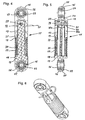
- FIG. 3 shows the spring element 11 in one of the FIG. 2 90 ° offset longitudinal section. Thereafter, the piston 13 from the collar 18 of the attachment eye 15, starting a flat profile, which forms a cylindrical portion 28 end.
- the section 28 is enclosed on the outside by the sleeve 14 and further serves to receive a transverse pin 29 fixed in the section 28.
- the double-sided axially extended transverse pin 29 positively engages with play in longitudinal guides 30a, 30b of the cylinder 12 and thus forms a stroke limitation and at the same time a captive , whereby all components of the spring element 11 are summarized secured against loss.
- FIGS. 4, 5 and 6 show the spring element 11 in a biased position.
- a spangenartig designed spring connector 31 is provided, with which the piston 13 is positioned in an end position relative to the cylinder 12.
- the cylinder 12 includes an annular groove 31 for the positive reception of the spring connector 31.
- the transverse pin 29 is partially supported on the spring connector 31 in the region of the longitudinal guide 30a, 30b.
Landscapes
- Engineering & Computer Science (AREA)
- General Engineering & Computer Science (AREA)
- Mechanical Engineering (AREA)
- Devices For Conveying Motion By Means Of Endless Flexible Members (AREA)
- Pistons, Piston Rings, And Cylinders (AREA)
- Valve Device For Special Equipments (AREA)
Claims (11)
- Elément de ressort (1, 11), utilisé dans un entraînement à moyen de traction d'un moteur à combustion interne, constitué d'un cylindre (2, 12), dans lequel un piston (3, 13) est guidé de manière déplaçable linéairement et est sollicité par force par un moyen de ressort (7, 17), le cylindre (2, 12) ainsi que le piston (3, 13) présentant, pour la fixation de l'élément de ressort (1, 11), à chaque fois un oeillet de fixation (5, 15 ; 6, 16) en coïncidence, caractérisé en ce que pour la limitation de course du moyen de ressort (1, 11), une goupille transversale (29, 33) associée au piston (3, 13) vient en prise par engagement positif dans un guide longitudinal (30a, 30b ; 34) du cylindre (2, 12).
- Elément de ressort selon la revendication 1, caractérisé en ce qu'une aiguille de corps de roulement d'un palier à aiguille courant dans le commerce est réalisée sous forme de goupille transversale (29, 33) pour la limitation de course dans le piston (3, 13).
- Elément de ressort selon la revendication 1, caractérisé en ce que l'on prévoit comme moyen de ressort (7, 17) un ressort de compression à boudin qui est supporté du côté du piston contre un épaulement (18) et du côté du cylindre contre un étage (19).
- Elément de ressort selon la revendication 1, caractérisé en ce que le moyen de ressort (7, 17) inséré entre le piston (3, 13) et le cylindre (2, 12) ne dépasse pas un contour extérieur du piston (3, 13) et du cylindre (2, 12).
- Elément de ressort selon la revendication 1, caractérisé en ce que le piston (13) est guidé par le biais d'une douille (14) dans le cylindre (12).
- Elément de ressort selon la revendication 5, caractérisé en ce que la douille (14) fermée ou fendue, formant une douille de palier lisse, est fixée par engagement positif et/ou par engagement par force sur le piston (13).
- Elément de ressort selon la revendication 1, caractérisé en ce que le cylindre (3) comprend une douille d'enveloppe (35) qui est entourée du côté extérieur par le moyen de ressort (7).
- Elément de ressort selon la revendication 5, caractérisé en ce que la douille (14, 5) est fabriquée en polyamide tel que du PA 66 H.
- Elément de ressort selon la revendication 1, caractérisé en ce que les composants cylindre (2, 12) et piston (3, 13) sont fabriqués en plastique.
- Elément de ressort selon la revendication 8, caractérisé en ce que du PA 66 est prévu avec une proportion de fibres de verre ≥ 35% en tant que matériau pour les composants piston (3, 13) et cylindre (2, 12).
- Elément de ressort selon la revendication 1, caractérisé en ce que l'élément de ressort (1, 11) peut être comprimé et/ou maintenu dans une position comprimée au moyen d'un dispositif séparé ou d'un étrier de fixation séparé.
Applications Claiming Priority (2)
| Application Number | Priority Date | Filing Date | Title |
|---|---|---|---|
| DE102007059657 | 2007-12-10 | ||
| PCT/EP2008/067093 WO2009074566A1 (fr) | 2007-12-10 | 2008-12-09 | Élément élastique mécanique pour transmissions par lien souple |
Publications (2)
| Publication Number | Publication Date |
|---|---|
| EP2217831A1 EP2217831A1 (fr) | 2010-08-18 |
| EP2217831B1 true EP2217831B1 (fr) | 2011-08-10 |
Family
ID=40380018
Family Applications (1)
| Application Number | Title | Priority Date | Filing Date |
|---|---|---|---|
| EP08859409A Active EP2217831B1 (fr) | 2007-12-10 | 2008-12-09 | Elément de suspension mécanique pour transmissions par lien souple |
Country Status (5)
| Country | Link |
|---|---|
| US (1) | US20100273591A1 (fr) |
| EP (1) | EP2217831B1 (fr) |
| CN (1) | CN101861478B (fr) |
| AT (1) | ATE519968T1 (fr) |
| WO (1) | WO2009074566A1 (fr) |
Families Citing this family (17)
| Publication number | Priority date | Publication date | Assignee | Title |
|---|---|---|---|---|
| DE102006039743A1 (de) * | 2006-08-24 | 2008-02-28 | Schaeffler Kg | Spanneinrichtung für ein Zugmittel, insbesondere einen Riemen oder eine Kette |
| DE102010049940A1 (de) | 2010-10-28 | 2012-05-03 | Schaeffler Technologies Gmbh & Co. Kg | Linear wirkendes Spannelement |
| DE102011002761B4 (de) * | 2011-01-17 | 2020-01-02 | Schaeffler Technologies AG & Co. KG | Zugmittelspannvorrichtung mit Sicherungselement sowie Verbrennungskraftmaschine mit einer solchen Zugmittelspannvorrichtung |
| DE102011004489A1 (de) | 2011-02-22 | 2012-08-23 | Schaeffler Technologies Gmbh & Co. Kg | Als Zugspanneinheit ausgeführte, linear wirkende Spanneinheit, die als Federmittel eine Druckfeder einschließt |
| DE102011004488A1 (de) | 2011-02-22 | 2012-08-23 | Schaeffler Technologies AG & Co. KG | Linearspanneinheit für Zugmitteltriebe mit einer integrierten Dämpfungseinrichtung |
| DE102011004487A1 (de) | 2011-02-22 | 2012-08-23 | Schaeffler Technologies AG & Co. KG | Linearspanneinheit für Zugmitteltriebe mit einer integrierten Dämpfungseinrichtung |
| DE102012200676B4 (de) | 2011-04-14 | 2019-11-07 | Schaeffler Technologies AG & Co. KG | Riemenspanner |
| DE102011007877A1 (de) | 2011-04-21 | 2012-10-25 | Schaeffler Technologies AG & Co. KG | Riemenspanner |
| DE102011084066B3 (de) * | 2011-10-06 | 2013-01-31 | Schaeffler Technologies AG & Co. KG | Spannvorrichtung |
| CN103335076A (zh) * | 2013-07-08 | 2013-10-02 | 昆山吉海实业公司 | 一种开式链条收紧器 |
| US20170138445A1 (en) * | 2014-06-27 | 2017-05-18 | Litens Automotive Partnership | Endless drive arrangement with active idler |
| DE102016204178A1 (de) | 2016-03-15 | 2017-09-21 | Schaeffler Technologies AG & Co. KG | Zugmittelspanner mit Anschlag |
| JP6659454B2 (ja) * | 2016-05-13 | 2020-03-04 | Ntn株式会社 | オートテンショナ |
| DE102016221797B4 (de) * | 2016-11-08 | 2020-03-26 | Schaeffler Technologies AG & Co. KG | Spannvorrichtung |
| WO2018132094A1 (fr) * | 2017-01-11 | 2018-07-19 | Borgwarner Inc. | Système anti-retour pour tendeur hydraulique |
| JP6882679B2 (ja) * | 2017-07-07 | 2021-06-02 | 株式会社椿本チエイン | テンショナ |
| US11111987B2 (en) * | 2017-10-10 | 2021-09-07 | Mobile Climate Control, Corp. | Counterforce drive-belt system |
Family Cites Families (19)
| Publication number | Priority date | Publication date | Assignee | Title |
|---|---|---|---|---|
| JPH068361Y2 (ja) * | 1987-09-07 | 1994-03-02 | 日鍛バルブ株式会社 | 液圧式テンシヨナ |
| JP2587694B2 (ja) * | 1988-12-29 | 1997-03-05 | 日本発条株式会社 | テンショナー |
| IT1228729B (it) * | 1989-03-15 | 1991-07-03 | Pirelli Transmissioni Ind Spa | Dispositivo tenditore per cinghia flessibile di trasmissione. |
| FR2644541B1 (fr) * | 1989-03-17 | 1994-07-01 | Hutchinson | Tendeur pour courroie de transmission de puissance |
| JPH0366957A (ja) * | 1989-08-01 | 1991-03-22 | Nhk Spring Co Ltd | テンショナ |
| FR2688565B1 (fr) * | 1992-03-12 | 1998-04-03 | Hutchinson | Tendeur pour courroie et systeme de transmission comportant un tel tendeur. |
| DE19533457B4 (de) * | 1995-09-09 | 2005-09-01 | Ina-Schaeffler Kg | Befestigungsauge für eine Spannvorrichtung |
| US5967921A (en) * | 1997-10-09 | 1999-10-19 | Borg-Warner Automotive, Inc. | Hydraulic chain tensioner with molded plastic body |
| FR2772857B1 (fr) | 1997-12-18 | 2000-02-11 | Hutchinson | Tendeur, moteur comportant un tel tendeur et procede de montage d'un tel tendeur |
| US6312351B1 (en) * | 1998-09-21 | 2001-11-06 | Borgwarner Inc. | Hydraulic tensioner with pivotal mount |
| FR2787540B1 (fr) * | 1998-12-22 | 2005-10-07 | Sachs Automotive France Sa | Tendeur hydraulique pour chaine ou lien sans fin pour l'equipement d'un moteur a combustion interne |
| JP4392930B2 (ja) * | 2000-01-12 | 2010-01-06 | 株式会社椿本チエイン | 油密封式テンショナ |
| DE10222752A1 (de) * | 2002-05-23 | 2003-12-04 | Ina Schaeffler Kg | Hydraulische Spannvorrichtung |
| DE10312752A1 (de) * | 2003-03-20 | 2004-11-11 | Ina-Schaeffler Kg | Zugmitteltrieb |
| BRPI0410064A (pt) * | 2003-05-06 | 2006-05-23 | Litens Automotive | tracionador linear, e, montagem de tracionador |
| JP4367834B2 (ja) * | 2003-09-19 | 2009-11-18 | 株式会社ショーワ | オートテンショナー |
| JP4540974B2 (ja) * | 2003-12-16 | 2010-09-08 | Ntn株式会社 | 補機駆動用ベルトの張力調整装置 |
| DE102004012141A1 (de) * | 2004-03-12 | 2005-09-29 | Ina-Schaeffler Kg | Zugmitteltrieb, insbesondere Riementrieb |
| EP1647737B1 (fr) * | 2004-10-15 | 2010-01-13 | Morse Tec Europe S.R.L. | Tendeur hydraulique avec un dispositif de non-retour et à moyens d 'anti-rotation déconnectables et procédé de déconnecter ces moyens |
-
2008
- 2008-12-09 AT AT08859409T patent/ATE519968T1/de active
- 2008-12-09 WO PCT/EP2008/067093 patent/WO2009074566A1/fr not_active Ceased
- 2008-12-09 US US12/747,015 patent/US20100273591A1/en not_active Abandoned
- 2008-12-09 CN CN200880116381.2A patent/CN101861478B/zh not_active Expired - Fee Related
- 2008-12-09 EP EP08859409A patent/EP2217831B1/fr active Active
Also Published As
| Publication number | Publication date |
|---|---|
| CN101861478A (zh) | 2010-10-13 |
| US20100273591A1 (en) | 2010-10-28 |
| CN101861478B (zh) | 2013-03-27 |
| ATE519968T1 (de) | 2011-08-15 |
| EP2217831A1 (fr) | 2010-08-18 |
| WO2009074566A1 (fr) | 2009-06-18 |
Similar Documents
| Publication | Publication Date | Title |
|---|---|---|
| EP2217831B1 (fr) | Elément de suspension mécanique pour transmissions par lien souple | |
| EP2347146B1 (fr) | Élément de tension linéaire | |
| EP2612053B1 (fr) | Poulie de tension à excentrique | |
| EP0195945A1 (fr) | Tendeur de chaîne | |
| WO2005121599A1 (fr) | Mecanisme de traction muni d'un dispositif de tension | |
| EP1794473B1 (fr) | Element de serrage hydraulique | |
| EP2957793A2 (fr) | Dispositif de tension de courroie | |
| EP3144563A2 (fr) | Dispositif de tension de courroie | |
| DE102012206664B4 (de) | Mechanische Kettenspanneinheit mit Federbandstahltragkörper und Keilnachstellvorrichtung | |
| DE102014209780A1 (de) | Exzenterspanner für einen Zugmitteltrieb eines Verbrennungsmotors | |
| EP1941182B1 (fr) | Unite de guidage pour mecanisme de traction | |
| DE102012200676B4 (de) | Riemenspanner | |
| DE19849892A1 (de) | Dichtelement für ein Ausrücklager | |
| WO2001071216A1 (fr) | Dispositif tendeur pour moyens d'entrainement | |
| DE102016202276B3 (de) | Exzenteranordnung insbesondere für eine Pumpe eines ABS-Systems sowie Pumpe für das ABS-System | |
| DE19953379A1 (de) | Reibkonus für eine Spannvorrichtung | |
| DE4433153A1 (de) | Spannvorrichtung | |
| WO2007009564A1 (fr) | Dispositif de tension de chaîne | |
| DE102004032082B4 (de) | Betätigungseinrichtung für eine Kupplung | |
| DE102015221296A1 (de) | Rollenstößel für eine Kolbenpumpe, Kolbenpumpe | |
| DE102005051652A1 (de) | Spannrolle für einen Zugmitteltrieb | |
| WO2005064203A1 (fr) | Dispositif de tension de courroie | |
| DE10360288A1 (de) | Mechanische Spannvorrichtung für Zugmittel mit gerichteter Reibdämpfung | |
| EP2469088A2 (fr) | Entraînement excentrique pour au moins un piston d'une pompe à piston | |
| WO2005111462A1 (fr) | Systeme tendeur dote d'au moins deux kraftmitteln |
Legal Events
| Date | Code | Title | Description |
|---|---|---|---|
| PUAI | Public reference made under article 153(3) epc to a published international application that has entered the european phase |
Free format text: ORIGINAL CODE: 0009012 |
|
| 17P | Request for examination filed |
Effective date: 20100712 |
|
| AK | Designated contracting states |
Kind code of ref document: A1 Designated state(s): AT BE BG CH CY CZ DE DK EE ES FI FR GB GR HR HU IE IS IT LI LT LU LV MC MT NL NO PL PT RO SE SI SK TR |
|
| AX | Request for extension of the european patent |
Extension state: AL BA MK RS |
|
| GRAP | Despatch of communication of intention to grant a patent |
Free format text: ORIGINAL CODE: EPIDOSNIGR1 |
|
| DAX | Request for extension of the european patent (deleted) | ||
| GRAS | Grant fee paid |
Free format text: ORIGINAL CODE: EPIDOSNIGR3 |
|
| GRAA | (expected) grant |
Free format text: ORIGINAL CODE: 0009210 |
|
| AK | Designated contracting states |
Kind code of ref document: B1 Designated state(s): AT BE BG CH CY CZ DE DK EE ES FI FR GB GR HR HU IE IS IT LI LT LU LV MC MT NL NO PL PT RO SE SI SK TR |
|
| REG | Reference to a national code |
Ref country code: GB Ref legal event code: FG4D Free format text: NOT ENGLISH |
|
| REG | Reference to a national code |
Ref country code: CH Ref legal event code: EP |
|
| REG | Reference to a national code |
Ref country code: IE Ref legal event code: FG4D Free format text: LANGUAGE OF EP DOCUMENT: GERMAN |
|
| REG | Reference to a national code |
Ref country code: DE Ref legal event code: R096 Ref document number: 502008004486 Country of ref document: DE Effective date: 20111013 |
|
| REG | Reference to a national code |
Ref country code: NL Ref legal event code: VDEP Effective date: 20110810 |
|
| LTIE | Lt: invalidation of european patent or patent extension |
Effective date: 20110810 |
|
| PG25 | Lapsed in a contracting state [announced via postgrant information from national office to epo] |
Ref country code: NO Free format text: LAPSE BECAUSE OF FAILURE TO SUBMIT A TRANSLATION OF THE DESCRIPTION OR TO PAY THE FEE WITHIN THE PRESCRIBED TIME-LIMIT Effective date: 20111110 Ref country code: SE Free format text: LAPSE BECAUSE OF FAILURE TO SUBMIT A TRANSLATION OF THE DESCRIPTION OR TO PAY THE FEE WITHIN THE PRESCRIBED TIME-LIMIT Effective date: 20110810 Ref country code: IS Free format text: LAPSE BECAUSE OF FAILURE TO SUBMIT A TRANSLATION OF THE DESCRIPTION OR TO PAY THE FEE WITHIN THE PRESCRIBED TIME-LIMIT Effective date: 20111210 Ref country code: PT Free format text: LAPSE BECAUSE OF FAILURE TO SUBMIT A TRANSLATION OF THE DESCRIPTION OR TO PAY THE FEE WITHIN THE PRESCRIBED TIME-LIMIT Effective date: 20111212 Ref country code: NL Free format text: LAPSE BECAUSE OF FAILURE TO SUBMIT A TRANSLATION OF THE DESCRIPTION OR TO PAY THE FEE WITHIN THE PRESCRIBED TIME-LIMIT Effective date: 20110810 Ref country code: LT Free format text: LAPSE BECAUSE OF FAILURE TO SUBMIT A TRANSLATION OF THE DESCRIPTION OR TO PAY THE FEE WITHIN THE PRESCRIBED TIME-LIMIT Effective date: 20110810 Ref country code: FI Free format text: LAPSE BECAUSE OF FAILURE TO SUBMIT A TRANSLATION OF THE DESCRIPTION OR TO PAY THE FEE WITHIN THE PRESCRIBED TIME-LIMIT Effective date: 20110810 Ref country code: HR Free format text: LAPSE BECAUSE OF FAILURE TO SUBMIT A TRANSLATION OF THE DESCRIPTION OR TO PAY THE FEE WITHIN THE PRESCRIBED TIME-LIMIT Effective date: 20110810 |
|
| PG25 | Lapsed in a contracting state [announced via postgrant information from national office to epo] |
Ref country code: SI Free format text: LAPSE BECAUSE OF FAILURE TO SUBMIT A TRANSLATION OF THE DESCRIPTION OR TO PAY THE FEE WITHIN THE PRESCRIBED TIME-LIMIT Effective date: 20110810 Ref country code: GR Free format text: LAPSE BECAUSE OF FAILURE TO SUBMIT A TRANSLATION OF THE DESCRIPTION OR TO PAY THE FEE WITHIN THE PRESCRIBED TIME-LIMIT Effective date: 20111111 Ref country code: CY Free format text: LAPSE BECAUSE OF FAILURE TO SUBMIT A TRANSLATION OF THE DESCRIPTION OR TO PAY THE FEE WITHIN THE PRESCRIBED TIME-LIMIT Effective date: 20110810 Ref country code: PL Free format text: LAPSE BECAUSE OF FAILURE TO SUBMIT A TRANSLATION OF THE DESCRIPTION OR TO PAY THE FEE WITHIN THE PRESCRIBED TIME-LIMIT Effective date: 20110810 Ref country code: LV Free format text: LAPSE BECAUSE OF FAILURE TO SUBMIT A TRANSLATION OF THE DESCRIPTION OR TO PAY THE FEE WITHIN THE PRESCRIBED TIME-LIMIT Effective date: 20110810 |
|
| RAP2 | Party data changed (patent owner data changed or rights of a patent transferred) |
Owner name: SCHAEFFLER TECHNOLOGIES AG & CO. KG |
|
| REG | Reference to a national code |
Ref country code: IE Ref legal event code: FD4D |
|
| REG | Reference to a national code |
Ref country code: CH Ref legal event code: PFA Owner name: SCHAEFFLER TECHNOLOGIES AG & CO. KG Free format text: SCHAEFFLER TECHNOLOGIES GMBH & CO. KG#INDUSTRIESTRASSE 1-3#91074 HERZOGENAURACH (DE) -TRANSFER TO- SCHAEFFLER TECHNOLOGIES AG & CO. KG#INDUSTRIESTRASSE 1-3#91074 HERZOGENAURACH (DE) |
|
| PG25 | Lapsed in a contracting state [announced via postgrant information from national office to epo] |
Ref country code: CZ Free format text: LAPSE BECAUSE OF FAILURE TO SUBMIT A TRANSLATION OF THE DESCRIPTION OR TO PAY THE FEE WITHIN THE PRESCRIBED TIME-LIMIT Effective date: 20110810 Ref country code: SK Free format text: LAPSE BECAUSE OF FAILURE TO SUBMIT A TRANSLATION OF THE DESCRIPTION OR TO PAY THE FEE WITHIN THE PRESCRIBED TIME-LIMIT Effective date: 20110810 Ref country code: IE Free format text: LAPSE BECAUSE OF FAILURE TO SUBMIT A TRANSLATION OF THE DESCRIPTION OR TO PAY THE FEE WITHIN THE PRESCRIBED TIME-LIMIT Effective date: 20110810 |
|
| PG25 | Lapsed in a contracting state [announced via postgrant information from national office to epo] |
Ref country code: EE Free format text: LAPSE BECAUSE OF FAILURE TO SUBMIT A TRANSLATION OF THE DESCRIPTION OR TO PAY THE FEE WITHIN THE PRESCRIBED TIME-LIMIT Effective date: 20110810 Ref country code: RO Free format text: LAPSE BECAUSE OF FAILURE TO SUBMIT A TRANSLATION OF THE DESCRIPTION OR TO PAY THE FEE WITHIN THE PRESCRIBED TIME-LIMIT Effective date: 20110810 Ref country code: IT Free format text: LAPSE BECAUSE OF FAILURE TO SUBMIT A TRANSLATION OF THE DESCRIPTION OR TO PAY THE FEE WITHIN THE PRESCRIBED TIME-LIMIT Effective date: 20110810 |
|
| PLBE | No opposition filed within time limit |
Free format text: ORIGINAL CODE: 0009261 |
|
| STAA | Information on the status of an ep patent application or granted ep patent |
Free format text: STATUS: NO OPPOSITION FILED WITHIN TIME LIMIT |
|
| PG25 | Lapsed in a contracting state [announced via postgrant information from national office to epo] |
Ref country code: DK Free format text: LAPSE BECAUSE OF FAILURE TO SUBMIT A TRANSLATION OF THE DESCRIPTION OR TO PAY THE FEE WITHIN THE PRESCRIBED TIME-LIMIT Effective date: 20110810 |
|
| BERE | Be: lapsed |
Owner name: SCHAEFFLER TECHNOLOGIES G.M.B.H. & CO. KG Effective date: 20111231 |
|
| 26N | No opposition filed |
Effective date: 20120511 |
|
| PG25 | Lapsed in a contracting state [announced via postgrant information from national office to epo] |
Ref country code: MC Free format text: LAPSE BECAUSE OF NON-PAYMENT OF DUE FEES Effective date: 20111231 |
|
| REG | Reference to a national code |
Ref country code: DE Ref legal event code: R097 Ref document number: 502008004486 Country of ref document: DE Effective date: 20120511 |
|
| REG | Reference to a national code |
Ref country code: FR Ref legal event code: ST Effective date: 20120831 |
|
| REG | Reference to a national code |
Ref country code: DE Ref legal event code: R081 Ref document number: 502008004486 Country of ref document: DE Owner name: SCHAEFFLER TECHNOLOGIES AG & CO. KG, DE Free format text: FORMER OWNER: SCHAEFFLER TECHNOLOGIES GMBH & CO. KG, 91074 HERZOGENAURACH, DE Effective date: 20120828 Ref country code: DE Ref legal event code: R081 Ref document number: 502008004486 Country of ref document: DE Owner name: SCHAEFFLER TECHNOLOGIES GMBH & CO. KG, DE Free format text: FORMER OWNER: SCHAEFFLER TECHNOLOGIES GMBH & CO. KG, 91074 HERZOGENAURACH, DE Effective date: 20120828 |
|
| PG25 | Lapsed in a contracting state [announced via postgrant information from national office to epo] |
Ref country code: BE Free format text: LAPSE BECAUSE OF NON-PAYMENT OF DUE FEES Effective date: 20111231 |
|
| PG25 | Lapsed in a contracting state [announced via postgrant information from national office to epo] |
Ref country code: MT Free format text: LAPSE BECAUSE OF FAILURE TO SUBMIT A TRANSLATION OF THE DESCRIPTION OR TO PAY THE FEE WITHIN THE PRESCRIBED TIME-LIMIT Effective date: 20110810 |
|
| PG25 | Lapsed in a contracting state [announced via postgrant information from national office to epo] |
Ref country code: ES Free format text: LAPSE BECAUSE OF FAILURE TO SUBMIT A TRANSLATION OF THE DESCRIPTION OR TO PAY THE FEE WITHIN THE PRESCRIBED TIME-LIMIT Effective date: 20111121 Ref country code: FR Free format text: LAPSE BECAUSE OF NON-PAYMENT OF DUE FEES Effective date: 20120102 |
|
| PG25 | Lapsed in a contracting state [announced via postgrant information from national office to epo] |
Ref country code: LU Free format text: LAPSE BECAUSE OF NON-PAYMENT OF DUE FEES Effective date: 20111209 |
|
| PG25 | Lapsed in a contracting state [announced via postgrant information from national office to epo] |
Ref country code: BG Free format text: LAPSE BECAUSE OF FAILURE TO SUBMIT A TRANSLATION OF THE DESCRIPTION OR TO PAY THE FEE WITHIN THE PRESCRIBED TIME-LIMIT Effective date: 20111110 |
|
| REG | Reference to a national code |
Ref country code: CH Ref legal event code: PL |
|
| PG25 | Lapsed in a contracting state [announced via postgrant information from national office to epo] |
Ref country code: TR Free format text: LAPSE BECAUSE OF FAILURE TO SUBMIT A TRANSLATION OF THE DESCRIPTION OR TO PAY THE FEE WITHIN THE PRESCRIBED TIME-LIMIT Effective date: 20110810 |
|
| PG25 | Lapsed in a contracting state [announced via postgrant information from national office to epo] |
Ref country code: CH Free format text: LAPSE BECAUSE OF NON-PAYMENT OF DUE FEES Effective date: 20121231 Ref country code: HU Free format text: LAPSE BECAUSE OF FAILURE TO SUBMIT A TRANSLATION OF THE DESCRIPTION OR TO PAY THE FEE WITHIN THE PRESCRIBED TIME-LIMIT Effective date: 20110810 Ref country code: LI Free format text: LAPSE BECAUSE OF NON-PAYMENT OF DUE FEES Effective date: 20121231 |
|
| REG | Reference to a national code |
Ref country code: DE Ref legal event code: R081 Ref document number: 502008004486 Country of ref document: DE Owner name: SCHAEFFLER TECHNOLOGIES AG & CO. KG, DE Free format text: FORMER OWNER: SCHAEFFLER TECHNOLOGIES AG & CO. KG, 91074 HERZOGENAURACH, DE Effective date: 20140218 Ref country code: DE Ref legal event code: R081 Ref document number: 502008004486 Country of ref document: DE Owner name: SCHAEFFLER TECHNOLOGIES GMBH & CO. KG, DE Free format text: FORMER OWNER: SCHAEFFLER TECHNOLOGIES AG & CO. KG, 91074 HERZOGENAURACH, DE Effective date: 20140218 |
|
| REG | Reference to a national code |
Ref country code: AT Ref legal event code: MM01 Ref document number: 519968 Country of ref document: AT Kind code of ref document: T Effective date: 20131209 |
|
| REG | Reference to a national code |
Ref country code: DE Ref legal event code: R081 Ref document number: 502008004486 Country of ref document: DE Owner name: SCHAEFFLER TECHNOLOGIES AG & CO. KG, DE Free format text: FORMER OWNER: SCHAEFFLER TECHNOLOGIES GMBH & CO. KG, 91074 HERZOGENAURACH, DE Effective date: 20150402 |
|
| PG25 | Lapsed in a contracting state [announced via postgrant information from national office to epo] |
Ref country code: AT Free format text: LAPSE BECAUSE OF NON-PAYMENT OF DUE FEES Effective date: 20131209 |
|
| PGFP | Annual fee paid to national office [announced via postgrant information from national office to epo] |
Ref country code: DE Payment date: 20230216 Year of fee payment: 15 |
|
| P01 | Opt-out of the competence of the unified patent court (upc) registered |
Effective date: 20230522 |
|
| REG | Reference to a national code |
Ref country code: DE Ref legal event code: R119 Ref document number: 502008004486 Country of ref document: DE |
|
| PG25 | Lapsed in a contracting state [announced via postgrant information from national office to epo] |
Ref country code: DE Free format text: LAPSE BECAUSE OF NON-PAYMENT OF DUE FEES Effective date: 20240702 |
|
| PG25 | Lapsed in a contracting state [announced via postgrant information from national office to epo] |
Ref country code: DE Free format text: LAPSE BECAUSE OF NON-PAYMENT OF DUE FEES Effective date: 20240702 |
|
| PGFP | Annual fee paid to national office [announced via postgrant information from national office to epo] |
Ref country code: GB Payment date: 20241224 Year of fee payment: 17 |