EP2218569A2 - Dispositif de fabrication de récipients en plastique - Google Patents
Dispositif de fabrication de récipients en plastique Download PDFInfo
- Publication number
- EP2218569A2 EP2218569A2 EP10153138A EP10153138A EP2218569A2 EP 2218569 A2 EP2218569 A2 EP 2218569A2 EP 10153138 A EP10153138 A EP 10153138A EP 10153138 A EP10153138 A EP 10153138A EP 2218569 A2 EP2218569 A2 EP 2218569A2
- Authority
- EP
- European Patent Office
- Prior art keywords
- mold
- bottom part
- parts
- closed state
- blow mold
- Prior art date
- Legal status (The legal status is an assumption and is not a legal conclusion. Google has not performed a legal analysis and makes no representation as to the accuracy of the status listed.)
- Granted
Links
- 239000004033 plastic Substances 0.000 title claims description 28
- 230000008878 coupling Effects 0.000 claims description 32
- 238000010168 coupling process Methods 0.000 claims description 32
- 238000005859 coupling reaction Methods 0.000 claims description 32
- 238000007664 blowing Methods 0.000 claims description 28
- 238000012546 transfer Methods 0.000 abstract description 2
- 238000000465 moulding Methods 0.000 description 21
- 230000007246 mechanism Effects 0.000 description 8
- 238000000071 blow moulding Methods 0.000 description 4
- 238000000034 method Methods 0.000 description 4
- 239000000969 carrier Substances 0.000 description 3
- 230000005540 biological transmission Effects 0.000 description 2
- 238000005461 lubrication Methods 0.000 description 2
- 230000008569 process Effects 0.000 description 2
- 238000007789 sealing Methods 0.000 description 2
- 238000013459 approach Methods 0.000 description 1
- 230000001419 dependent effect Effects 0.000 description 1
- 238000011161 development Methods 0.000 description 1
- 230000018109 developmental process Effects 0.000 description 1
- 230000000694 effects Effects 0.000 description 1
- 230000002349 favourable effect Effects 0.000 description 1
- 238000003780 insertion Methods 0.000 description 1
- 230000037431 insertion Effects 0.000 description 1
- 238000004519 manufacturing process Methods 0.000 description 1
- 239000000463 material Substances 0.000 description 1
- 230000009467 reduction Effects 0.000 description 1
- 238000007493 shaping process Methods 0.000 description 1
- 229920001169 thermoplastic Polymers 0.000 description 1
- 239000004416 thermosoftening plastic Substances 0.000 description 1
- 230000001131 transforming effect Effects 0.000 description 1
Images


Classifications
-
- B—PERFORMING OPERATIONS; TRANSPORTING
- B29—WORKING OF PLASTICS; WORKING OF SUBSTANCES IN A PLASTIC STATE IN GENERAL
- B29C—SHAPING OR JOINING OF PLASTICS; SHAPING OF MATERIAL IN A PLASTIC STATE, NOT OTHERWISE PROVIDED FOR; AFTER-TREATMENT OF THE SHAPED PRODUCTS, e.g. REPAIRING
- B29C49/00—Blow-moulding, i.e. blowing a preform or parison to a desired shape within a mould; Apparatus therefor
- B29C49/42—Component parts, details or accessories; Auxiliary operations
- B29C49/56—Opening, closing or clamping means
- B29C49/5601—Mechanically operated, i.e. closing or opening of the mould parts is done by mechanic means
- B29C49/5602—Mechanically operated, i.e. closing or opening of the mould parts is done by mechanic means using cams
-
- B—PERFORMING OPERATIONS; TRANSPORTING
- B29—WORKING OF PLASTICS; WORKING OF SUBSTANCES IN A PLASTIC STATE IN GENERAL
- B29C—SHAPING OR JOINING OF PLASTICS; SHAPING OF MATERIAL IN A PLASTIC STATE, NOT OTHERWISE PROVIDED FOR; AFTER-TREATMENT OF THE SHAPED PRODUCTS, e.g. REPAIRING
- B29C49/00—Blow-moulding, i.e. blowing a preform or parison to a desired shape within a mould; Apparatus therefor
- B29C49/42—Component parts, details or accessories; Auxiliary operations
- B29C49/48—Moulds
- B29C2049/4879—Moulds characterised by mould configurations
- B29C2049/4892—Mould halves consisting of an independent main and bottom part
-
- B—PERFORMING OPERATIONS; TRANSPORTING
- B29—WORKING OF PLASTICS; WORKING OF SUBSTANCES IN A PLASTIC STATE IN GENERAL
- B29C—SHAPING OR JOINING OF PLASTICS; SHAPING OF MATERIAL IN A PLASTIC STATE, NOT OTHERWISE PROVIDED FOR; AFTER-TREATMENT OF THE SHAPED PRODUCTS, e.g. REPAIRING
- B29C49/00—Blow-moulding, i.e. blowing a preform or parison to a desired shape within a mould; Apparatus therefor
- B29C49/42—Component parts, details or accessories; Auxiliary operations
- B29C49/56—Opening, closing or clamping means
- B29C2049/566—Locking means
- B29C2049/5661—Mechanical
-
- B—PERFORMING OPERATIONS; TRANSPORTING
- B29—WORKING OF PLASTICS; WORKING OF SUBSTANCES IN A PLASTIC STATE IN GENERAL
- B29C—SHAPING OR JOINING OF PLASTICS; SHAPING OF MATERIAL IN A PLASTIC STATE, NOT OTHERWISE PROVIDED FOR; AFTER-TREATMENT OF THE SHAPED PRODUCTS, e.g. REPAIRING
- B29C33/00—Moulds or cores; Details thereof or accessories therefor
- B29C33/20—Opening, closing or clamping
- B29C33/26—Opening, closing or clamping by pivotal movement
-
- B—PERFORMING OPERATIONS; TRANSPORTING
- B29—WORKING OF PLASTICS; WORKING OF SUBSTANCES IN A PLASTIC STATE IN GENERAL
- B29C—SHAPING OR JOINING OF PLASTICS; SHAPING OF MATERIAL IN A PLASTIC STATE, NOT OTHERWISE PROVIDED FOR; AFTER-TREATMENT OF THE SHAPED PRODUCTS, e.g. REPAIRING
- B29C49/00—Blow-moulding, i.e. blowing a preform or parison to a desired shape within a mould; Apparatus therefor
- B29C49/42—Component parts, details or accessories; Auxiliary operations
- B29C49/56—Opening, closing or clamping means
- B29C49/5613—Opening, closing or clamping means characterised by connected mould part movement, e.g. bottom part movement is linked to mould half movement
Definitions
- the present invention relates to an apparatus for producing plastic containers, and more particularly to an apparatus for forming plastic preforms into plastic containers.
- Such devices have been known from the prior art for some time. It is customary to expand plastic preforms, usually made of PET, as part of a blow to plastic containers. For this purpose, the plastic preform is introduced into a blow mold and expanded against an inner wall of this blow mold.
- the DE 10 2007 022 638 A1 describes a device for blow molding containers.
- one of the mold carriers is immovable and the other mold carrier is pivotally supported by a support structure and a bottom part is relative to each of both mold carriers arranged movably, wherein the bottom part relative to the mold carriers has a movement path which is provided both with a running in a longitudinal direction of the blowing station component and with a transverse to the longitudinal direction component.
- this approach when bringing the bottom part of the blow mold is relatively expensive.
- EP 1 789 247 B1 is also a device for blow molding containers known, in which case also both the mold carrier and the bottom part are arranged mechanically positionable and the mold carrier and the bottom part of a common mechanical drive means are permanently coupled together.
- the DE 100 2711 A1 describes a blow mold and a method for closing this blow mold.
- two mold halves are pivotally connected together by a connecting axis.
- a closure device to close the two mold halves.
- the US 2008/0254161 A1 describes a molding apparatus for the production of thermoplastic containers.
- a blowing nozzle is provided which can move in an axial direction and two mold halves form the blow mold, which is surrounded by a sloping edge.
- the tuyere itself has a corresponding surrounding element which locks the upper part of the closed tuyere.
- the present invention has for its object to provide an apparatus for forming plastic preforms to plastic containers available, which is designed to be simpler to handle over the prior art.
- improved locking mechanisms for blow molding are to be provided.
- these closure elements have at least a first mold part and a second mold part, wherein the first mold part and the second mold part between the closed position and the open position with respect to each other are movable.
- the closure elements on a bottom part which is movable relative to the mold parts to complete the cavity in one direction. According to the invention, the bottom part or a movement of the bottom part initiates at least the closing of the molded parts and / or the locking of the molded parts in a closed state of the blow mold.
- the movements of the mold parts and the bottom part are usually controlled by independent curves. If a coupling between a movement of the mold parts and the bottom part is provided, usually the mold parts are driven and a movement of the moldings leads by a coupling also to a movement of the bottom part.
- a drive of the bottom part takes place and a closing and / or locking of the molded parts takes place via this drive.
- the invention makes use of the fact that a control of the movement of the bottom part on guide curves is mechanically easier to handle than a movement of the (two) moldings.
- the mold parts surround the container in a closed state of the blow mold in the circumferential direction.
- the mold parts surround the container completely in the circumferential direction and are particularly preferably formed symmetrically to each other.
- the bottom part locked in a closed state, the two mold parts together.
- the bottom part is usually held when folding the two mold parts and in this way the bottom part is locked by closing the moldings.
- the blow mold is arranged as part of a blowing station on a rotating blowing wheel.
- This blower wheel preferably rotates continuously during operation.
- stationarily arranged guide curves can be used.
- some of the stationary guide curves can be replaced by coupling a plurality of closure elements.
- the use of a guide curve for the ground is the only driving element for the closure elements.
- pneumatic transmission pneumatic or hydraulic cylinders are used to dispense with stationary curves for closure elements can. This is particularly advantageous in relation to aseptic machines with a clean room, since lubrication of the stationary curves can be dispensed with.
- a locking device is arranged on a bottom part, which locks the two molded parts together in a closed state of the blow mold.
- the locking device on a first locking element, which contacts the first molded part in a closed state of the blow mold and a second locking element, which contacts the second molded part in a closed state of the blow mold.
- these two locking elements are arranged rigidly relative to each other. In this way it can be achieved that they are locked against each other by a frictional grip between the locking elements and portions of the moldings.
- the two mold parts are arranged at least in sections between the two locking elements. More specifically, a lower portion of the molded parts is between the arranged two locking elements, and the mold parts are pressed together by these two locking elements.
- the two sections of the molded parts are arranged in a radial direction of the blow mold between the two locking elements.
- a contact surface between the locking elements and the mold parts widens in the direction of the cavity. In this way, insertion bevels are created, which facilitates a placement of the bottom part of the two mold parts.
- the locking elements simultaneously serve as closing elements for the moldings.
- the locking elements could be formed, for example, upwards or in the direction of the mold parts as an expanding cone, so that is reached or initiated by a movement of the bottom part on the two mold parts to the closing movement of the moldings.
- At least one molded part has an inclined surface in a contact region with the bottom part.
- Both mold parts advantageously have an inclined surface in the said contact region with the bottom part.
- the inclined surface is conical.
- At least one of the two molded parts is pivotable about an axis extending parallel to a longitudinal direction and, whereby closing and opening of the molded parts is achieved by this pivoting.
- both mold parts are pivotable about said axis.
- a movement of the bottom part is coupled to a movement of at least one molded part.
- the device advantageously has a coupling device which couples a movement of the bottom part at least temporarily with a movement of at least one molded part.
- the coupling device has a first coupling element which connects the first molded part to the bottom part and second coupling element which connects the second molded part to the bottom part. In this way, a particularly reliable coupling is achieved.
- a coupling device between the bottom part and the molded part on a movable guide curve, in which the bottom part is preferably in constant engagement with the molded part, so that large loads and lubrication of this coupling device can be avoided.
- the coupling device converts a movement of the bottom part in a longitudinal direction of the blow mold into a movement of at least one shaped part in a direction perpendicular to this longitudinal direction.
- the device has at least one pneumatic drive device for moving the bottom part. Accordingly, a pneumatic drive device for moving the moldings could be used.
- the coupling between a mold carrier and the bottom part is not made over a horizontal curve, but over a substantially vertical curve, since this is less problematic in the adjustment of the moldings in the assembly.
- the locking is here, as mentioned above, advantageously made by a kind of cone, which from below into the mold carrier, d. H. engages in the two mold parts and in particular also sits on the bottom part.
- rollers may be attached to a cone-like surface of the locking elements to minimize friction of the cone surfaces.
- detents for the rollers or for projections attached to the closure elements can be attached to the closure elements in order to hold the closure elements in the locking position.
- a release mechanism for example a cam, can release the lock at the desired moment.
- it would be conceivable to dispense with a bottom centering if appropriate power transmission means, which couple the movement of the mold parts to the movement of the bottom part, are precisely designed. If a pneumatic element, such as a pneumatic cylinder is used to move the bottom part, it is possible that this pneumatic cylinder moves only to an end position or to a stop position on a lever. In this way, a reduction of wear is possible.
- the device further comprises a blowing nozzle device, which is movable relative to the molded parts and which closes the blow mold in the closed state in one direction.
- a blowing nozzle device which is movable relative to the molded parts and which closes the blow mold in the closed state in one direction.
- the blast nozzle means closes the two moldings above and the bottom part closes the blow mold from below, so that in this way can be completely dispensed with closure means for the moldings.
- blow molding segments are arranged on the molded parts, against the inner wall of which the containers are expanded.
- a movement of the blowing nozzle device is coupled to a movement of the bottom part and / or the molded parts.
- the blowing nozzle device locks the two molded parts together in the closed state of the blow mold.
- movements of the blowing nozzle device of at least one of the molded parts and the bottom part are coupled to one another.
- a coupling of an additional locking element for the molded parts can also be included in this coupling.
- the present invention is further directed to a plant for treating containers and in particular for transforming plastic preforms into containers, this system having a plurality of devices or blowing stations of the above type, which are also arranged a rotatable carrier or blowing wheel.
- the present invention is also directed to a method for forming plastic preforms into plastic containers, wherein closure elements of at least one blow mold cooperate with each other to form the blow mold between an open state and a closed state in which the blow mold forms a cavity within which the plastic preforms Plastic containers are expanded to transfer, and wherein the closure elements comprise at least a first mold part and a second mold part, wherein the first mold part and the second mold part between the closed position and the open position with respect to each other are moved and in a closed state, the moldings are locked together , and wherein the closure elements comprise a bottom part, which is moved relative to the mold parts to complete the cavity in one direction. Initiated according to the invention the bottom part at least the closing of the mold parts and / or the locking of the mold parts in a closed state of the blow mold.
- the bottom part locked in a closed state, the two mold parts together.
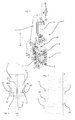
- Fig. 1 shows a perspective view of a device or blowing station according to the invention for expanding plastic preforms to plastic containers.
- This device 1 has a blow mold, which is formed by a first molded part 4 and a second molded part 6.
- one of these mold parts 4,6 is pivotable relative to the other, in which case in particular both mold parts 4,6 can be pivoted.
- a (only partially shown) bottom part 8 is provided, which closes the entire blow mold from below.
- a blowing nozzle device 14 is present, which is lowered here from above onto the two mold parts 4, 6 and which contains a blowing nozzle for expanding the plastic preforms into plastic containers.
- the mold parts 4, 6, together with the bottom part 8 and the blowing nozzle device 14, constitute the closure elements for the blow mold.
- blowing stations 1 are arranged on a rotatable blowing wheel.
- blow stations shown is also conceivable for cycle machines.
- the reference numeral 15 refers to a stretching rod, which serves for stretching the plastic preforms.
- a lifting unit for moving the blowing nozzle device 14 is arranged on a support 5.
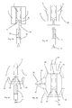
- Fig. 2 shows a schematic partial view of in Fig. 1
- the reference symbol L denotes the longitudinal direction of the container and here also the device.
- the reference numeral 8 denotes a bottom part, which can be moved here by means of a drive device, such as a pneumatic cylinder 16, in the direction of the axis L and which in the in Fig. 2 shown closed state, the two mold parts 4 and 6 locked together. More specifically, for this purpose, the bottom part 8 has two locking elements 24 and 26, which in a closed state Clasp the two molded parts 4 and 6 and press them together.
- the two mold parts 4 and 6 have for this purpose inclined surfaces 4a and 6a, which cooperate with corresponding extending from bottom to top inclined surfaces 24a, 26a on the locking elements 24 and 26 together. In this way, by a movement of the bottom part from bottom to top, the two mold parts 4 and 6 are pressed against each other and locked it. Opening the moldings is only possible after removal or lowering of the bottom part.
- the Fig. 3 shows a further embodiment of a locking mechanism according to the invention.
- a bayonet-type closure is provided for this mechanism. It is possible that the bottom part 8 is first moved up to the mold parts 4 and 6 and is then rotated. By this rotation, it comes with appropriately designed interior areas of the mold parts 4 and 6 to a lock of the two mold parts 4 and 6 against each other.
- Fig. 4a schematically shows a representation for illustrating a coupling device 30 between a bottom part 8 and the two mold parts 4 and 6.
- a first coupling element 34 and a second coupling element 36 are provided, wherein the first coupling element 34, the first mold part 4 and a movement thereof coupled to a movement of the bottom part 8.
- the second coupling element 36 couples a movement of the second mold part 6 to the bottom part 8. If, starting from the in Fig. 4a shown position, the lifting rod 18 is lowered, causing the two coupling elements 34 and 36, that the two mold halves 4 and 6 are pressed apart and in this way, for example, already prepared container can be removed.
- Fig. 4b shows further illustration of a device according to the invention.
- a part of a bottom part 8 extends between the two mold parts 4 and 6 and further component, which here also includes the two locking elements 24 and 26, surrounds the two mold parts 4 and 6 and presses them together.
- sealing connection between the bottom part 8 and the two mold parts. 4 and 6 reached.
- sealing elements made of a flexible material it would also be possible for sealing elements made of a flexible material to be arranged on the molded parts 4, 6 and / or the bottom part in order to achieve a favorable seal when pressed together accordingly.
- Fig. 4c shows a further embodiment of a device according to the invention, in which case both the coupling by the two coupling elements 34 and 36 is shown as well as the locking of the two mold parts 4 and 6 by the two locking elements 24 and 26.
- the reference numeral 19 refers to a bearing point on the hydraulic cylinder 16 is arranged.
- Fig. 4d shows a further embodiment of a device according to the invention, in which the movement of a blowing nozzle device 14 is coupled to the other movements.
- a pneumatic cylinder 50 is provided here, which causes via second coupling elements 52 and 54 that the bottom part 8 and the blowing nozzle device 14 are moved apart or towards each other.
- the two mold parts 4 and 6 are in turn coupled to the bottom part via the first coupling elements 34 and 36 already described above, so that in this case all closure elements are coupled together and therefore only one curve or one pneumatic cylinder is necessary for driving.
- the reference numeral 42 refers to a blowing nozzle to pressurize the container with a gaseous medium and in particular air.
- the reference numerals 44, 46 are characterized in the direction of the mold parts 4, 6 widening inclined surfaces in order to lock the mold parts against each other.
- the bottom part 8 and the blowing nozzle device 14 are guided by means of linear guides 48, 49.
- Fig. 5 shows a further illustration for illustrating a blow mold according to the invention. Again, an engagement between the bottom part 8 and the two mold parts 4 and 6 is possible, wherein, as shown, the two mold parts 4 and 6 against each other about a pivot shaft 3 are pivotable.
- Fig. 6a shows a first embodiment for shaping a movement of the bottom part 8.
- a pneumatic cylinder 62 is provided, which directly the bottom part 8 in the in Fig. 1 shown Moved longitudinally.
- a threaded spindle (62) can be provided, which is driven by a drive element, such as a nut.
- a four-bar mechanism is used to raise the bottom part 8. More specifically, four articulated levers 66 are provided here, which are arranged both on a bottom plate 67 via propeller shafts 69 and on the bottom part 8 via propeller shafts 68. In this case, the bottom part 8 is not only raised, but also moved sideways.
- a mechanism 71 is provided, on which two side parts 72 and 74 are arranged. In these side parts curved grooves 73, 75 are provided, which also allow a movement of the bottom part 8 on the one hand upwards but here also in the other direction.
- the spatial orientation of the bottom part 8 is preferably not changed in this embodiment.
- the bottom part 8 is articulated in each case via a pivot shaft 76 below the two mold parts 4 and 6 and can be folded around this shaft 76 to the two mold parts 4 and 6.
- the molded parts 4 and 6 are also here about their pivot shaft 73 against each other pivotally. While at the in Fig. 6d As shown, the pivot shaft 76 extends in the region of both mold parts 4 and 6, it is in the in Fig. 6e embodiment shown in the region of only one of the two mold parts 4, 6 are arranged.
- Fig. 6e shows a further embodiment for illustrating a movement of the bottom part 8.
- a flywheel 84 is provided, which is arranged on a support plate 82 via a shaft 83 and on the bottom part 8 via a propeller shaft 81.
- Fig. 6g shows a further illustration to illustrate the lock. It can be seen here that the two mold parts 4 and 6 are locked by the bottom part 8 and the blowing nozzle device 14 when the bottom part 8 and the blowing nozzle device 14 are moved towards each other.
- tapered surfaces 4a, 4b, 6a, 6b are again provided on the shaped parts, which effect a locking of the two mold parts 4 and 6 against each other.
- the bottom part 8 and also the blowing nozzle device 14 have corresponding oblique surfaces, wherein only the inclined surfaces 8a of the bottom part are shown here.
Landscapes
- Engineering & Computer Science (AREA)
- Manufacturing & Machinery (AREA)
- Mechanical Engineering (AREA)
- Blow-Moulding Or Thermoforming Of Plastics Or The Like (AREA)
- Moulds For Moulding Plastics Or The Like (AREA)
Applications Claiming Priority (1)
| Application Number | Priority Date | Filing Date | Title |
|---|---|---|---|
| DE102009008632A DE102009008632A1 (de) | 2009-02-12 | 2009-02-12 | Vorrichtung zum Herstellen von Kunststoffbehältnissen |
Publications (3)
| Publication Number | Publication Date |
|---|---|
| EP2218569A2 true EP2218569A2 (fr) | 2010-08-18 |
| EP2218569A3 EP2218569A3 (fr) | 2014-01-29 |
| EP2218569B1 EP2218569B1 (fr) | 2019-12-04 |
Family
ID=42194820
Family Applications (1)
| Application Number | Title | Priority Date | Filing Date |
|---|---|---|---|
| EP10153138.2A Active EP2218569B1 (fr) | 2009-02-12 | 2010-02-10 | Dispositif de fabrication de récipients en plastique |
Country Status (4)
| Country | Link |
|---|---|
| US (1) | US8231379B2 (fr) |
| EP (1) | EP2218569B1 (fr) |
| CN (1) | CN101823328B (fr) |
| DE (1) | DE102009008632A1 (fr) |
Cited By (5)
| Publication number | Priority date | Publication date | Assignee | Title |
|---|---|---|---|---|
| EP2495086A1 (fr) * | 2011-03-04 | 2012-09-05 | Krones AG | Souffleuse dotée d'un verrouillage de moule de soufflage dans la salle stérile |
| EP2626190A1 (fr) * | 2012-02-09 | 2013-08-14 | Sidel Participations | Dispositif de formage de recipients |
| EP2422956A3 (fr) * | 2010-08-31 | 2014-02-12 | Krones AG | Moule de soufflage |
| EP2917019B1 (fr) | 2012-11-12 | 2017-01-04 | KHS Corpoplast GmbH | Procédé et dispositif de moulage par soufflage de récipients comprenant un dispositif d'entraînement et des séquences de mouvements couplées |
| IT202100000323A1 (it) * | 2021-01-11 | 2022-07-11 | Smi Spa | Macchina per la soffiatura o stiro-soffiatura di bottiglie in materiale polimerico |
Families Citing this family (14)
| Publication number | Priority date | Publication date | Assignee | Title |
|---|---|---|---|---|
| DE102010022130A1 (de) | 2010-05-20 | 2011-11-24 | Krones Ag | Vorrichtung zum Umformen von Kunststoffvorformlingen mit Sterilraum |
| DE102010039803A1 (de) * | 2010-08-26 | 2012-03-01 | Krones Aktiengesellschaft | Blasform |
| FR2998206B1 (fr) * | 2012-11-19 | 2015-01-16 | Sidel Participations | Procede de fabrication de recipients, comprenant une operation retardee de boxage |
| EP2767384B1 (fr) * | 2013-02-18 | 2016-11-23 | Discma AG | Moule pour mouler un corps creux à partir d'une préforme et machine comprenant un tel moule |
| CN103171140B (zh) * | 2013-03-19 | 2015-07-01 | 江苏新美星包装机械股份有限公司 | 吹瓶机 |
| CN103341963B (zh) * | 2013-06-21 | 2015-08-05 | 杭州中亚机械股份有限公司 | 一种旋转吹瓶机的模架开合装置 |
| DE102014111590A1 (de) * | 2014-08-13 | 2016-02-18 | Krones Ag | Vorrichtung zum Umformen von Kunststoffvorformlingen zu Kunststoffbehältnissen |
| CN104441583B (zh) * | 2014-12-16 | 2016-08-17 | 广州达意隆包装机械股份有限公司 | 一种吹瓶机边模与底模联动机构的柔性结构 |
| WO2017059930A1 (fr) * | 2015-10-09 | 2017-04-13 | Krones Ag | Dispositif de moulage par soufflage présentant un accouplement de fond à actionnement automatique et procédé pour le fonctionnement du dispositif associé |
| DE102017008446A1 (de) * | 2017-09-08 | 2019-03-14 | Khs Corpoplast Gmbh | Verfahren, Vorrichtung, Arbeitsrad und Umformstation für die Herstellung von gefüllten Behältern aus temperaturkonditionierten Vorformlingen |
| EP3695946B1 (fr) * | 2019-02-14 | 2022-04-13 | LM Wind Power A/S | Aligneur de moule pour moule de coque de pale d'éolienne |
| CN116261511A (zh) * | 2020-08-20 | 2023-06-13 | 日精Asb机械株式会社 | 吹塑成型装置 |
| JP2022125007A (ja) * | 2021-02-16 | 2022-08-26 | サクミ・イモラ・ソシエタ・コーペラティバ | 容器をブロー成形するための装置 |
| US12467558B1 (en) * | 2024-05-09 | 2025-11-11 | The Boeing Company | Assembly to form a seal on a conduit |
Citations (4)
| Publication number | Priority date | Publication date | Assignee | Title |
|---|---|---|---|---|
| DE1002711B (de) | 1951-06-26 | 1957-02-21 | Heinrich Heins | Selbsttaetig schliessender Gashahn |
| EP1789247B1 (fr) | 2004-09-18 | 2008-10-08 | SIG Technology Ltd. | Dispositif de moulage par souffler de récipients |
| US20080254161A1 (en) | 2007-04-13 | 2008-10-16 | Sidel Participations | Moulding device for the manufacture of thermoplastic containers by blow moulding or stretch-blow moulding |
| DE102007022638A1 (de) | 2007-05-15 | 2008-11-20 | Sig Technology Ag | Vorrichtung zur Blasformung von Behältern |
Family Cites Families (17)
| Publication number | Priority date | Publication date | Assignee | Title |
|---|---|---|---|---|
| US1529622A (en) * | 1922-02-14 | 1925-03-10 | Haley Reuben | Sectional mold |
| US2269553A (en) * | 1936-10-08 | 1942-01-13 | Roessler George | Glass machine and method of making glass |
| US2361553A (en) * | 1940-08-23 | 1944-10-31 | Walter O Luertzing | Apparatus for manufacturing hollow glass articles |
| US2974362A (en) * | 1956-12-20 | 1961-03-14 | Specialty Papers Company | Apparatus for molding hollow articles of plastic |
| US3050773A (en) * | 1958-07-26 | 1962-08-28 | Reinold Hagen | Process and apparatus for manufacturing blown articles |
| US3195186A (en) * | 1962-06-13 | 1965-07-20 | Inv S Finance Corp | Apparatus for clamping mold parts |
| US3470284A (en) * | 1965-05-14 | 1969-09-30 | Gundlach Gmbh Aug | Device for producing refractory bodies and a method of producing such bodies |
| US3504403A (en) * | 1967-03-20 | 1970-04-07 | Brown Machine Co Of Michigan | Differential pressure plastic forming machine partible mold mechanism for forming articles in a plastic sheet |
| US3753641A (en) * | 1969-12-22 | 1973-08-21 | Continental Can Co | Mold for articles having undercut portions |
| US3694124A (en) * | 1970-10-16 | 1972-09-26 | Robert W Saumsiegle | Injection blow molding equipment |
| DE2950723A1 (de) * | 1979-12-17 | 1981-07-09 | tpT Machinery Corp., Norwalk, Conn. | Schliesseinheit fuer formen zur blasformgebung von kunststoffhohlkoerpern |
| JPS60234825A (ja) * | 1984-05-09 | 1985-11-21 | Japan Steel Works Ltd:The | 中空成形金型組立体 |
| JPS60234824A (ja) * | 1984-05-09 | 1985-11-21 | Japan Steel Works Ltd:The | 中空成形金型組立体 |
| US5064366A (en) * | 1990-05-15 | 1991-11-12 | Nissei Asb Machine Co., Ltd. | Blow mold |
| KR100432248B1 (ko) * | 1996-09-02 | 2004-08-16 | 닛세이 에이. 에스. 비 기카이 가부시키가이샤 | 가열중공성형장치및가열중공성형방법 |
| US6929462B1 (en) * | 2000-11-08 | 2005-08-16 | Hammonton Mold Co. Inc. | Mold part guide mechanism |
| FR2876942B1 (fr) * | 2004-10-22 | 2008-08-15 | Sidel Sas | Installation de soufflage pour la fabrication de recipients en matiere thermoplastique |
-
2009
- 2009-02-12 DE DE102009008632A patent/DE102009008632A1/de not_active Withdrawn
-
2010
- 2010-02-10 EP EP10153138.2A patent/EP2218569B1/fr active Active
- 2010-02-10 US US12/703,449 patent/US8231379B2/en not_active Expired - Fee Related
- 2010-02-10 CN CN2010101271159A patent/CN101823328B/zh not_active Expired - Fee Related
Patent Citations (4)
| Publication number | Priority date | Publication date | Assignee | Title |
|---|---|---|---|---|
| DE1002711B (de) | 1951-06-26 | 1957-02-21 | Heinrich Heins | Selbsttaetig schliessender Gashahn |
| EP1789247B1 (fr) | 2004-09-18 | 2008-10-08 | SIG Technology Ltd. | Dispositif de moulage par souffler de récipients |
| US20080254161A1 (en) | 2007-04-13 | 2008-10-16 | Sidel Participations | Moulding device for the manufacture of thermoplastic containers by blow moulding or stretch-blow moulding |
| DE102007022638A1 (de) | 2007-05-15 | 2008-11-20 | Sig Technology Ag | Vorrichtung zur Blasformung von Behältern |
Cited By (10)
| Publication number | Priority date | Publication date | Assignee | Title |
|---|---|---|---|---|
| EP2422956A3 (fr) * | 2010-08-31 | 2014-02-12 | Krones AG | Moule de soufflage |
| EP2495086A1 (fr) * | 2011-03-04 | 2012-09-05 | Krones AG | Souffleuse dotée d'un verrouillage de moule de soufflage dans la salle stérile |
| US8708681B2 (en) | 2011-03-04 | 2014-04-29 | Krones Ag | Blow-moulding machine with blow mould locking in the clean room |
| EP2626190A1 (fr) * | 2012-02-09 | 2013-08-14 | Sidel Participations | Dispositif de formage de recipients |
| FR2986735A1 (fr) * | 2012-02-09 | 2013-08-16 | Sidel Participations | Dispositif pour le boxage par un fond de moule d'une embase d'un recipient au cours du faconnage |
| EP2917019B1 (fr) | 2012-11-12 | 2017-01-04 | KHS Corpoplast GmbH | Procédé et dispositif de moulage par soufflage de récipients comprenant un dispositif d'entraînement et des séquences de mouvements couplées |
| EP2917019B2 (fr) † | 2012-11-12 | 2021-05-26 | KHS Corpoplast GmbH | Procédé et dispositif de moulage par soufflage de récipients comprenant un dispositif d'entraînement et des séquences de mouvements couplées |
| IT202100000323A1 (it) * | 2021-01-11 | 2022-07-11 | Smi Spa | Macchina per la soffiatura o stiro-soffiatura di bottiglie in materiale polimerico |
| EP4026682A1 (fr) * | 2021-01-11 | 2022-07-13 | SMI S.p.A. | Machine de soufflage ou d'étirage-soufflage de bouteilles en polymère |
| US11623383B2 (en) | 2021-01-11 | 2023-04-11 | Smi S.P.A. | Blowing or stretch-blowing machine for bottles made of polymer material |
Also Published As
| Publication number | Publication date |
|---|---|
| US20100203187A1 (en) | 2010-08-12 |
| EP2218569A3 (fr) | 2014-01-29 |
| US8231379B2 (en) | 2012-07-31 |
| EP2218569B1 (fr) | 2019-12-04 |
| DE102009008632A1 (de) | 2010-08-19 |
| CN101823328B (zh) | 2013-11-06 |
| CN101823328A (zh) | 2010-09-08 |
Similar Documents
| Publication | Publication Date | Title |
|---|---|---|
| EP2218569B1 (fr) | Dispositif de fabrication de récipients en plastique | |
| EP2263854B1 (fr) | Machine de formage par soufflage entraînée de manière électrique et le procédé | |
| EP2511070B1 (fr) | Dispositif et procédé de transformation de préformes en matière synthétique en récipients en plastique avec mouvements couplés de verrouillage et d'oscillation | |
| EP2740582B1 (fr) | Machine de formage par soufflage et procédé apparenté. | |
| EP3294525B1 (fr) | Poste de moulage pour les machines de moulage par soufflage sans coussins de pression | |
| DE102011015666B4 (de) | Verfahren sowie Vorrichtung zur Herstellung von Behältern | |
| EP2311625B1 (fr) | Porte-moule doté d'un dispositif d'entraînement | |
| EP2368692B2 (fr) | Dispositif de moulage par soufflage doté d'un mécanisme de verrouillage contrôlé | |
| EP1970190A2 (fr) | Dispositif de traitement de récipients | |
| EP3359367B1 (fr) | Dispositif et procédé pour mouler des préformes en matériau synthétique en récipients en matériau synthétique à l'aide d'un dispositif de couplage | |
| DE602004012617T2 (de) | Streckblasmaschine mit mechanisch angetriebenem streckhelfer | |
| DE202013104120U1 (de) | Vorrichtung zum Umformen von Kunststoffvorformlingen zu Kunststoffbehältnissen mit asymmetrischer Blasformöffnungsbewegung | |
| EP3558631B2 (fr) | Procédé et dispositif pour le moulage par soufflage de récipients présentant une partie de fond mobile | |
| EP3558632B1 (fr) | Procédé et dispositif pour le moulage par soufflage de contenants à l'aide d'une partie inférieure mobile | |
| EP2455208B1 (fr) | Dispositif et procédé pour amortissement d'un système de levage du fond de moule | |
| WO2023232386A1 (fr) | Système de moulage par soufflage et son procédé de fonctionnement | |
| EP4299280B1 (fr) | Dispositif et procédé de déformation d'ébauches en plastique en récipients en plastique | |
| WO2018224479A1 (fr) | Ensemble moule de soufflage servant à transformer des préformes en matière plastique en contenants en matière plastique comportant des éléments de déviation de force et un procédé dédié à cet effet et un dispositif servant à transformer des préformes en matière plastique comportant un dispositif de verrouillage | |
| DE102006005417B4 (de) | Eigenstabiles Schäumwerkzeug mit Mittel zur Erzeugung eines Schließdruckes | |
| EP3619018B1 (fr) | Procédé servant à faire fonctionner un dispositif servant à façonner des préformes en matière plastique en des récipients en matière plastique, et dispositif | |
| DE202014105296U1 (de) | Blasformmaschine mit Gleitlagern zur Blasformträgerbewegung | |
| DE102014115118A1 (de) | Streckblasmaschine mit Getriebeeinheit zum Antrieb der Reckstange | |
| EP4442429A1 (fr) | Outil et procédé de fabrication d'un récipient moulé par injection-soufflage | |
| DE102021130572A1 (de) | Vorrichtung und Verfahren zum Herstellen von Getränkebehältnissen mit verringertem Ausschuss | |
| DE102013102563A1 (de) | Blasformmaschine mit kombinierter Führung und Dichtung der Reckstange |
Legal Events
| Date | Code | Title | Description |
|---|---|---|---|
| PUAI | Public reference made under article 153(3) epc to a published international application that has entered the european phase |
Free format text: ORIGINAL CODE: 0009012 |
|
| AK | Designated contracting states |
Kind code of ref document: A2 Designated state(s): AT BE BG CH CY CZ DE DK EE ES FI FR GB GR HR HU IE IS IT LI LT LU LV MC MK MT NL NO PL PT RO SE SI SK SM TR |
|
| AX | Request for extension of the european patent |
Extension state: AL BA RS |
|
| RIN1 | Information on inventor provided before grant (corrected) |
Inventor name: SCHMID, FLORIAN Inventor name: WINZINGER, FRANK Inventor name: WITTMANN, CHRISTIAN |
|
| RIC1 | Information provided on ipc code assigned before grant |
Ipc: B29C 49/56 20060101AFI20130102BHEP |
|
| PUAL | Search report despatched |
Free format text: ORIGINAL CODE: 0009013 |
|
| AK | Designated contracting states |
Kind code of ref document: A3 Designated state(s): AT BE BG CH CY CZ DE DK EE ES FI FR GB GR HR HU IE IS IT LI LT LU LV MC MK MT NL NO PL PT RO SE SI SK SM TR |
|
| AX | Request for extension of the european patent |
Extension state: AL BA RS |
|
| RIC1 | Information provided on ipc code assigned before grant |
Ipc: B29C 49/56 20060101AFI20131220BHEP |
|
| 17P | Request for examination filed |
Effective date: 20140729 |
|
| RBV | Designated contracting states (corrected) |
Designated state(s): AT BE BG CH CY CZ DE DK EE ES FI FR GB GR HR HU IE IS IT LI LT LU LV MC MK MT NL NO PL PT RO SE SI SK SM TR |
|
| STAA | Information on the status of an ep patent application or granted ep patent |
Free format text: STATUS: EXAMINATION IS IN PROGRESS |
|
| 17Q | First examination report despatched |
Effective date: 20190104 |
|
| GRAP | Despatch of communication of intention to grant a patent |
Free format text: ORIGINAL CODE: EPIDOSNIGR1 |
|
| STAA | Information on the status of an ep patent application or granted ep patent |
Free format text: STATUS: GRANT OF PATENT IS INTENDED |
|
| INTG | Intention to grant announced |
Effective date: 20190726 |
|
| GRAS | Grant fee paid |
Free format text: ORIGINAL CODE: EPIDOSNIGR3 |
|
| GRAA | (expected) grant |
Free format text: ORIGINAL CODE: 0009210 |
|
| STAA | Information on the status of an ep patent application or granted ep patent |
Free format text: STATUS: THE PATENT HAS BEEN GRANTED |
|
| RIN1 | Information on inventor provided before grant (corrected) |
Inventor name: WITTMANN, CHRISTIAN Inventor name: SCHMID, FLORIAN Inventor name: WINZINGER, FRANK |
|
| AK | Designated contracting states |
Kind code of ref document: B1 Designated state(s): AT BE BG CH CY CZ DE DK EE ES FI FR GB GR HR HU IE IS IT LI LT LU LV MC MK MT NL NO PL PT RO SE SI SK SM TR |
|
| REG | Reference to a national code |
Ref country code: GB Ref legal event code: FG4D Free format text: NOT ENGLISH |
|
| REG | Reference to a national code |
Ref country code: CH Ref legal event code: EP |
|
| REG | Reference to a national code |
Ref country code: AT Ref legal event code: REF Ref document number: 1208836 Country of ref document: AT Kind code of ref document: T Effective date: 20191215 |
|
| REG | Reference to a national code |
Ref country code: DE Ref legal event code: R096 Ref document number: 502010016391 Country of ref document: DE |
|
| REG | Reference to a national code |
Ref country code: IE Ref legal event code: FG4D Free format text: LANGUAGE OF EP DOCUMENT: GERMAN |
|
| REG | Reference to a national code |
Ref country code: NL Ref legal event code: MP Effective date: 20191204 |
|
| REG | Reference to a national code |
Ref country code: LT Ref legal event code: MG4D |
|
| PG25 | Lapsed in a contracting state [announced via postgrant information from national office to epo] |
Ref country code: FI Free format text: LAPSE BECAUSE OF FAILURE TO SUBMIT A TRANSLATION OF THE DESCRIPTION OR TO PAY THE FEE WITHIN THE PRESCRIBED TIME-LIMIT Effective date: 20191204 Ref country code: BG Free format text: LAPSE BECAUSE OF FAILURE TO SUBMIT A TRANSLATION OF THE DESCRIPTION OR TO PAY THE FEE WITHIN THE PRESCRIBED TIME-LIMIT Effective date: 20200304 Ref country code: SE Free format text: LAPSE BECAUSE OF FAILURE TO SUBMIT A TRANSLATION OF THE DESCRIPTION OR TO PAY THE FEE WITHIN THE PRESCRIBED TIME-LIMIT Effective date: 20191204 Ref country code: LV Free format text: LAPSE BECAUSE OF FAILURE TO SUBMIT A TRANSLATION OF THE DESCRIPTION OR TO PAY THE FEE WITHIN THE PRESCRIBED TIME-LIMIT Effective date: 20191204 Ref country code: LT Free format text: LAPSE BECAUSE OF FAILURE TO SUBMIT A TRANSLATION OF THE DESCRIPTION OR TO PAY THE FEE WITHIN THE PRESCRIBED TIME-LIMIT Effective date: 20191204 Ref country code: ES Free format text: LAPSE BECAUSE OF FAILURE TO SUBMIT A TRANSLATION OF THE DESCRIPTION OR TO PAY THE FEE WITHIN THE PRESCRIBED TIME-LIMIT Effective date: 20191204 Ref country code: GR Free format text: LAPSE BECAUSE OF FAILURE TO SUBMIT A TRANSLATION OF THE DESCRIPTION OR TO PAY THE FEE WITHIN THE PRESCRIBED TIME-LIMIT Effective date: 20200305 Ref country code: NO Free format text: LAPSE BECAUSE OF FAILURE TO SUBMIT A TRANSLATION OF THE DESCRIPTION OR TO PAY THE FEE WITHIN THE PRESCRIBED TIME-LIMIT Effective date: 20200304 |
|
| PG25 | Lapsed in a contracting state [announced via postgrant information from national office to epo] |
Ref country code: HR Free format text: LAPSE BECAUSE OF FAILURE TO SUBMIT A TRANSLATION OF THE DESCRIPTION OR TO PAY THE FEE WITHIN THE PRESCRIBED TIME-LIMIT Effective date: 20191204 |
|
| PG25 | Lapsed in a contracting state [announced via postgrant information from national office to epo] |
Ref country code: NL Free format text: LAPSE BECAUSE OF FAILURE TO SUBMIT A TRANSLATION OF THE DESCRIPTION OR TO PAY THE FEE WITHIN THE PRESCRIBED TIME-LIMIT Effective date: 20191204 Ref country code: EE Free format text: LAPSE BECAUSE OF FAILURE TO SUBMIT A TRANSLATION OF THE DESCRIPTION OR TO PAY THE FEE WITHIN THE PRESCRIBED TIME-LIMIT Effective date: 20191204 Ref country code: CZ Free format text: LAPSE BECAUSE OF FAILURE TO SUBMIT A TRANSLATION OF THE DESCRIPTION OR TO PAY THE FEE WITHIN THE PRESCRIBED TIME-LIMIT Effective date: 20191204 Ref country code: RO Free format text: LAPSE BECAUSE OF FAILURE TO SUBMIT A TRANSLATION OF THE DESCRIPTION OR TO PAY THE FEE WITHIN THE PRESCRIBED TIME-LIMIT Effective date: 20191204 Ref country code: PT Free format text: LAPSE BECAUSE OF FAILURE TO SUBMIT A TRANSLATION OF THE DESCRIPTION OR TO PAY THE FEE WITHIN THE PRESCRIBED TIME-LIMIT Effective date: 20200429 |
|
| PG25 | Lapsed in a contracting state [announced via postgrant information from national office to epo] |
Ref country code: IS Free format text: LAPSE BECAUSE OF FAILURE TO SUBMIT A TRANSLATION OF THE DESCRIPTION OR TO PAY THE FEE WITHIN THE PRESCRIBED TIME-LIMIT Effective date: 20200404 Ref country code: SK Free format text: LAPSE BECAUSE OF FAILURE TO SUBMIT A TRANSLATION OF THE DESCRIPTION OR TO PAY THE FEE WITHIN THE PRESCRIBED TIME-LIMIT Effective date: 20191204 Ref country code: SM Free format text: LAPSE BECAUSE OF FAILURE TO SUBMIT A TRANSLATION OF THE DESCRIPTION OR TO PAY THE FEE WITHIN THE PRESCRIBED TIME-LIMIT Effective date: 20191204 |
|
| REG | Reference to a national code |
Ref country code: DE Ref legal event code: R097 Ref document number: 502010016391 Country of ref document: DE |
|
| REG | Reference to a national code |
Ref country code: CH Ref legal event code: PL |
|
| PLBE | No opposition filed within time limit |
Free format text: ORIGINAL CODE: 0009261 |
|
| STAA | Information on the status of an ep patent application or granted ep patent |
Free format text: STATUS: NO OPPOSITION FILED WITHIN TIME LIMIT |
|
| REG | Reference to a national code |
Ref country code: BE Ref legal event code: MM Effective date: 20200229 |
|
| PG25 | Lapsed in a contracting state [announced via postgrant information from national office to epo] |
Ref country code: DK Free format text: LAPSE BECAUSE OF FAILURE TO SUBMIT A TRANSLATION OF THE DESCRIPTION OR TO PAY THE FEE WITHIN THE PRESCRIBED TIME-LIMIT Effective date: 20191204 Ref country code: LU Free format text: LAPSE BECAUSE OF NON-PAYMENT OF DUE FEES Effective date: 20200210 Ref country code: MC Free format text: LAPSE BECAUSE OF FAILURE TO SUBMIT A TRANSLATION OF THE DESCRIPTION OR TO PAY THE FEE WITHIN THE PRESCRIBED TIME-LIMIT Effective date: 20191204 |
|
| 26N | No opposition filed |
Effective date: 20200907 |
|
| PG25 | Lapsed in a contracting state [announced via postgrant information from national office to epo] |
Ref country code: LI Free format text: LAPSE BECAUSE OF NON-PAYMENT OF DUE FEES Effective date: 20200229 Ref country code: PL Free format text: LAPSE BECAUSE OF FAILURE TO SUBMIT A TRANSLATION OF THE DESCRIPTION OR TO PAY THE FEE WITHIN THE PRESCRIBED TIME-LIMIT Effective date: 20191204 Ref country code: SI Free format text: LAPSE BECAUSE OF FAILURE TO SUBMIT A TRANSLATION OF THE DESCRIPTION OR TO PAY THE FEE WITHIN THE PRESCRIBED TIME-LIMIT Effective date: 20191204 Ref country code: CH Free format text: LAPSE BECAUSE OF NON-PAYMENT OF DUE FEES Effective date: 20200229 |
|
| PG25 | Lapsed in a contracting state [announced via postgrant information from national office to epo] |
Ref country code: IE Free format text: LAPSE BECAUSE OF NON-PAYMENT OF DUE FEES Effective date: 20200210 |
|
| PG25 | Lapsed in a contracting state [announced via postgrant information from national office to epo] |
Ref country code: BE Free format text: LAPSE BECAUSE OF NON-PAYMENT OF DUE FEES Effective date: 20200229 |
|
| GBPC | Gb: european patent ceased through non-payment of renewal fee |
Effective date: 20200304 |
|
| REG | Reference to a national code |
Ref country code: AT Ref legal event code: MM01 Ref document number: 1208836 Country of ref document: AT Kind code of ref document: T Effective date: 20200210 |
|
| PG25 | Lapsed in a contracting state [announced via postgrant information from national office to epo] |
Ref country code: GB Free format text: LAPSE BECAUSE OF NON-PAYMENT OF DUE FEES Effective date: 20200304 |
|
| PGFP | Annual fee paid to national office [announced via postgrant information from national office to epo] |
Ref country code: FR Payment date: 20210112 Year of fee payment: 12 Ref country code: IT Payment date: 20210112 Year of fee payment: 12 |
|
| PG25 | Lapsed in a contracting state [announced via postgrant information from national office to epo] |
Ref country code: AT Free format text: LAPSE BECAUSE OF NON-PAYMENT OF DUE FEES Effective date: 20200210 |
|
| PGFP | Annual fee paid to national office [announced via postgrant information from national office to epo] |
Ref country code: DE Payment date: 20210126 Year of fee payment: 12 |
|
| PG25 | Lapsed in a contracting state [announced via postgrant information from national office to epo] |
Ref country code: TR Free format text: LAPSE BECAUSE OF FAILURE TO SUBMIT A TRANSLATION OF THE DESCRIPTION OR TO PAY THE FEE WITHIN THE PRESCRIBED TIME-LIMIT Effective date: 20191204 Ref country code: MT Free format text: LAPSE BECAUSE OF FAILURE TO SUBMIT A TRANSLATION OF THE DESCRIPTION OR TO PAY THE FEE WITHIN THE PRESCRIBED TIME-LIMIT Effective date: 20191204 Ref country code: CY Free format text: LAPSE BECAUSE OF FAILURE TO SUBMIT A TRANSLATION OF THE DESCRIPTION OR TO PAY THE FEE WITHIN THE PRESCRIBED TIME-LIMIT Effective date: 20191204 |
|
| PG25 | Lapsed in a contracting state [announced via postgrant information from national office to epo] |
Ref country code: MK Free format text: LAPSE BECAUSE OF FAILURE TO SUBMIT A TRANSLATION OF THE DESCRIPTION OR TO PAY THE FEE WITHIN THE PRESCRIBED TIME-LIMIT Effective date: 20191204 |
|
| REG | Reference to a national code |
Ref country code: DE Ref legal event code: R119 Ref document number: 502010016391 Country of ref document: DE |
|
| PG25 | Lapsed in a contracting state [announced via postgrant information from national office to epo] |
Ref country code: FR Free format text: LAPSE BECAUSE OF NON-PAYMENT OF DUE FEES Effective date: 20220228 |
|
| PG25 | Lapsed in a contracting state [announced via postgrant information from national office to epo] |
Ref country code: DE Free format text: LAPSE BECAUSE OF NON-PAYMENT OF DUE FEES Effective date: 20220901 |
|
| PG25 | Lapsed in a contracting state [announced via postgrant information from national office to epo] |
Ref country code: IT Free format text: LAPSE BECAUSE OF NON-PAYMENT OF DUE FEES Effective date: 20220210 |