EP2218892A2 - Aube de guidage refroidie pour le conduit d'échappement de turbine à gaz - Google Patents
Aube de guidage refroidie pour le conduit d'échappement de turbine à gaz Download PDFInfo
- Publication number
- EP2218892A2 EP2218892A2 EP10151897A EP10151897A EP2218892A2 EP 2218892 A2 EP2218892 A2 EP 2218892A2 EP 10151897 A EP10151897 A EP 10151897A EP 10151897 A EP10151897 A EP 10151897A EP 2218892 A2 EP2218892 A2 EP 2218892A2
- Authority
- EP
- European Patent Office
- Prior art keywords
- vane
- duct
- plate
- cooling
- interior
- Prior art date
- Legal status (The legal status is an assumption and is not a legal conclusion. Google has not performed a legal analysis and makes no representation as to the accuracy of the status listed.)
- Granted
Links
- 239000012530 fluid Substances 0.000 claims abstract description 12
- 238000001816 cooling Methods 0.000 description 25
- 239000007789 gas Substances 0.000 description 7
- 238000013461 design Methods 0.000 description 3
- 238000013021 overheating Methods 0.000 description 3
- 230000008901 benefit Effects 0.000 description 2
- 239000002826 coolant Substances 0.000 description 2
- 230000005855 radiation Effects 0.000 description 2
- 238000012546 transfer Methods 0.000 description 2
- 238000013459 approach Methods 0.000 description 1
- 238000005266 casting Methods 0.000 description 1
- 239000011248 coating agent Substances 0.000 description 1
- 238000000576 coating method Methods 0.000 description 1
- 238000010586 diagram Methods 0.000 description 1
- 230000000694 effects Effects 0.000 description 1
- 238000010438 heat treatment Methods 0.000 description 1
- 238000000034 method Methods 0.000 description 1
- 238000000926 separation method Methods 0.000 description 1
- 230000003068 static effect Effects 0.000 description 1
Images

Classifications
-
- F—MECHANICAL ENGINEERING; LIGHTING; HEATING; WEAPONS; BLASTING
- F01—MACHINES OR ENGINES IN GENERAL; ENGINE PLANTS IN GENERAL; STEAM ENGINES
- F01D—NON-POSITIVE DISPLACEMENT MACHINES OR ENGINES, e.g. STEAM TURBINES
- F01D25/00—Component parts, details, or accessories, not provided for in, or of interest apart from, other groups
- F01D25/30—Exhaust heads, chambers, or the like
-
- F—MECHANICAL ENGINEERING; LIGHTING; HEATING; WEAPONS; BLASTING
- F01—MACHINES OR ENGINES IN GENERAL; ENGINE PLANTS IN GENERAL; STEAM ENGINES
- F01D—NON-POSITIVE DISPLACEMENT MACHINES OR ENGINES, e.g. STEAM TURBINES
- F01D9/00—Stators
- F01D9/06—Fluid supply conduits to nozzles or the like
- F01D9/065—Fluid supply or removal conduits traversing the working fluid flow, e.g. for lubrication-, cooling-, or sealing fluids
-
- F—MECHANICAL ENGINEERING; LIGHTING; HEATING; WEAPONS; BLASTING
- F01—MACHINES OR ENGINES IN GENERAL; ENGINE PLANTS IN GENERAL; STEAM ENGINES
- F01D—NON-POSITIVE DISPLACEMENT MACHINES OR ENGINES, e.g. STEAM TURBINES
- F01D5/00—Blades; Blade-carrying members; Heating, heat-insulating, cooling or antivibration means on the blades or the members
- F01D5/12—Blades
- F01D5/14—Form or construction
- F01D5/18—Hollow blades, i.e. blades with cooling or heating channels or cavities; Heating, heat-insulating or cooling means on blades
- F01D5/187—Convection cooling
-
- F—MECHANICAL ENGINEERING; LIGHTING; HEATING; WEAPONS; BLASTING
- F01—MACHINES OR ENGINES IN GENERAL; ENGINE PLANTS IN GENERAL; STEAM ENGINES
- F01D—NON-POSITIVE DISPLACEMENT MACHINES OR ENGINES, e.g. STEAM TURBINES
- F01D9/00—Stators
- F01D9/02—Nozzles; Nozzle boxes; Stator blades; Guide conduits, e.g. individual nozzles
- F01D9/04—Nozzles; Nozzle boxes; Stator blades; Guide conduits, e.g. individual nozzles forming ring or sector
- F01D9/041—Nozzles; Nozzle boxes; Stator blades; Guide conduits, e.g. individual nozzles forming ring or sector using blades
-
- F—MECHANICAL ENGINEERING; LIGHTING; HEATING; WEAPONS; BLASTING
- F02—COMBUSTION ENGINES; HOT-GAS OR COMBUSTION-PRODUCT ENGINE PLANTS
- F02C—GAS-TURBINE PLANTS; AIR INTAKES FOR JET-PROPULSION PLANTS; CONTROLLING FUEL SUPPLY IN AIR-BREATHING JET-PROPULSION PLANTS
- F02C7/00—Features, components parts, details or accessories, not provided for in, or of interest apart form groups F02C1/00 - F02C6/00; Air intakes for jet-propulsion plants
- F02C7/12—Cooling of plants
- F02C7/16—Cooling of plants characterised by cooling medium
- F02C7/18—Cooling of plants characterised by cooling medium the medium being gaseous, e.g. air
-
- F—MECHANICAL ENGINEERING; LIGHTING; HEATING; WEAPONS; BLASTING
- F02—COMBUSTION ENGINES; HOT-GAS OR COMBUSTION-PRODUCT ENGINE PLANTS
- F02C—GAS-TURBINE PLANTS; AIR INTAKES FOR JET-PROPULSION PLANTS; CONTROLLING FUEL SUPPLY IN AIR-BREATHING JET-PROPULSION PLANTS
- F02C7/00—Features, components parts, details or accessories, not provided for in, or of interest apart form groups F02C1/00 - F02C6/00; Air intakes for jet-propulsion plants
- F02C7/20—Mounting or supporting of plant; Accommodating heat expansion or creep
-
- F—MECHANICAL ENGINEERING; LIGHTING; HEATING; WEAPONS; BLASTING
- F02—COMBUSTION ENGINES; HOT-GAS OR COMBUSTION-PRODUCT ENGINE PLANTS
- F02K—JET-PROPULSION PLANTS
- F02K9/00—Rocket-engine plants, i.e. plants carrying both fuel and oxidant therefor; Control thereof
- F02K9/08—Rocket-engine plants, i.e. plants carrying both fuel and oxidant therefor; Control thereof using solid propellants
- F02K9/32—Constructional parts; Details not otherwise provided for
-
- F—MECHANICAL ENGINEERING; LIGHTING; HEATING; WEAPONS; BLASTING
- F02—COMBUSTION ENGINES; HOT-GAS OR COMBUSTION-PRODUCT ENGINE PLANTS
- F02K—JET-PROPULSION PLANTS
- F02K9/00—Rocket-engine plants, i.e. plants carrying both fuel and oxidant therefor; Control thereof
- F02K9/08—Rocket-engine plants, i.e. plants carrying both fuel and oxidant therefor; Control thereof using solid propellants
- F02K9/32—Constructional parts; Details not otherwise provided for
- F02K9/40—Cooling arrangements
-
- F—MECHANICAL ENGINEERING; LIGHTING; HEATING; WEAPONS; BLASTING
- F05—INDEXING SCHEMES RELATING TO ENGINES OR PUMPS IN VARIOUS SUBCLASSES OF CLASSES F01-F04
- F05D—INDEXING SCHEME FOR ASPECTS RELATING TO NON-POSITIVE-DISPLACEMENT MACHINES OR ENGINES, GAS-TURBINES OR JET-PROPULSION PLANTS
- F05D2240/00—Components
- F05D2240/10—Stators
- F05D2240/12—Fluid guiding means, e.g. vanes
-
- Y—GENERAL TAGGING OF NEW TECHNOLOGICAL DEVELOPMENTS; GENERAL TAGGING OF CROSS-SECTIONAL TECHNOLOGIES SPANNING OVER SEVERAL SECTIONS OF THE IPC; TECHNICAL SUBJECTS COVERED BY FORMER USPC CROSS-REFERENCE ART COLLECTIONS [XRACs] AND DIGESTS
- Y02—TECHNOLOGIES OR APPLICATIONS FOR MITIGATION OR ADAPTATION AGAINST CLIMATE CHANGE
- Y02T—CLIMATE CHANGE MITIGATION TECHNOLOGIES RELATED TO TRANSPORTATION
- Y02T50/00—Aeronautics or air transport
- Y02T50/60—Efficient propulsion technologies, e.g. for aircraft
Definitions
- the present invention relates to a vane and is concerned particularly, although not exclusively, with a vane for an exhaust duct of an engine, such as an aircraft engine.
- the vane In the exhaust duct of a gas turbine engine a plurality of vanes or struts are attached to the duct casing and extend between walls of the duct, to support the duct and to maintain its shape. These so-called “exit guide vanes” are disposed in the path of hot exhaust gases from the engine and so are prone to becoming very hot themselves.
- the vane is designed as a hollow structure which allows the flow of cooling air in its interior.
- the cooling air may be supplied at relatively high pressure from the compressor of the engine, or may be bypass air which is drawn into the vane from outside the exhaust duct, and which is at a relatively low pressure.
- the cooling air is directed into the interior of the vane and ultimately exits the interior via one or more exit apertures or, in the case of high pressure compressor air, via holes in the vane surface, to join the core flow - so called "film cooling".
- vanes which are cooled with scooped bypass air, at lower pressure are less effectively cooled.
- scoop-fed vanes in the prior art have been less effectively cooled is that the flow of cooling air is relatively low and little or no attempt has been made to control the internal flow path.
- the pressure drop available cannot guarantee that the cooling air will change direction sufficiently to flow along the internal surfaces of the vane. Accordingly, there are areas of the vane that are not cooled, or are cooled insufficiently. This can lead to uneven thermal expansion of certain parts and possibly overheating of the internal load bearing structure, by heat convection and radiation.
- the relatively low pressure drop in scoop-fed vanes is also insufficient to allow the use of film cooling on the hot external surface of the vane.
- embodiments of the present invention aim to provide a vane in which at least some of the aforementioned problems are at least partially overcome.
- a vane for a duct wherein the vane comprises a vane plate, an interior strut and an internal plate disposed therebetween, and wherein the vane further comprises a fluid inlet arranged in use to direct fluid from outside the duct into an interior of the vane.
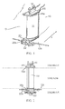
- FIG. 1 this shows generally at 10 an exit guide vane mounted in an exhaust duct 12 of a gas turbine engine (not shown).
- the vane 10 comprises a vane plate 14 and a shear web 16 within the plate 14 acting as a strut, the ends of which are secured to the exhaust duct casing, and which extends across the entire width of the exhaust duct 12.
- the purpose of the web 16 is to support the duct and maintain its shape, preventing the walls of the duct from moving relative to each other.
- the vane plate 14 may be held only by a loose friction fit in each of the grommets so that it can "float" relative to the web - ie it can expand thermally in the core flow of hot exhaust gases which thermal expansion is not restricted by the web 16 or the duct walls.
- the extent to which the vane can expand thermally is limited only by the depth of the grommet and the length of the vane plate, although if a large expansion range is required the vane plate can be fixed at one end - ie in respect of one of the grommets - to prevent it from becoming detached from the grommet.
- the system works for both radial and lateral growth and can be applied to circular or to rectangular ducts.
- an air inlet in the form of a scoop 22, positioned below the duct wall 12a, arranged to direct cooling air to the interior of the vane plate 14 for the purpose of cooling both the vane plate 14 and the shear web 16, as will be described in more detail below.
- the scoop 22 draws in so-called bypass air from the exterior of the exhaust duct.
- Figure 2 shows the vane of Figure 1 in front view with the broken lines indicating the separation between the cooling bypass air and hot core flow.
- Figure 3 shows schematically a plan of the vane of Figures 1 and 2 with the grommets and duct walls removed for clarity.
- the vane plate 14 defines a cavity 24 within which the structural shear web 16 extends between upper and lower duct walls. Between the plate 14 and the web 16 is located an internal cooling member in the form of a wall 26 which is of substantially the same vertical length as the plate 14. A gap 28 between the vane plate 14 and internal wall 26 is arranged to receive cooling bypass air from the scoop 22 as will be described below with reference to Figure 4 .
- Figure 4 is a part sectional view of the vane assembly viewed from the side, with the direction of flow of exhaust gases being depicted by arrow A and that of bypass air by arrow B (broken lines).
- cooling bypass air enters the interior of the vane 10 through the scoop 22 and is directed upwards into the gap 28 between the vane plate 14 and the internal wall 26 by the internal surfaces of the scoop 22.
- the cooling bypass air cools the interior wall 26 which helps to prevent overheating of the web 16 by radiation from the hot vane plate 16 in use.
- the directed bypass air also cools the interior surfaces of the vane plate itself. Cooling air also enters the cavity 24 behind the vane plates 14 at upper 30, and lower, 32 locations and a surface of a second scoop, or baffle, 34 is utilised to encourage the cooling flow to pass over the shear web 16 to help maintain a low temperature.
- the above mentioned embodiment has a number of advantages when compared with previously considered vanes. Firstly, the arrangement of a floating vane plate allows the vane plate to be thermally unconstrained so that a coating can be applied to it if necessary. In addition this allows the duct casing to move without affecting the functionality of the cooling system.
- the scoop 22 being an integral part of the lower grommet, helps to reduce the number of castings and parts within the assembly. This also helps to reduce the possibility of leakage of air from joints.
- a secondary air scoop directs flow over the shear web to maximise the cooling of the structure, and the internal cooled wall 26 constrains flow from the integrated scoop 22 into the interior passage 28, conformal to the inner surface of the vane which increases coolant velocity, and therefore raises convective heat transfer rates.
- the above described invention may be utilised on any static or rotating structure which is held within a main engine gas path, such as turbine and compressor stators and turbine and compressor vanes. It may be adapted to a contained structure such as a whole tube or vane with a scoop at one end as well as leading edges. It may be used in the main combustor or reheat system for flame gutters, support structures, airspray stems and heads, combustor can supports and igniters, IGVs, OGVs and NGVs. It may be of use in recuperated designs and heat exchangers.
- the present invention can also be used in cases where heating is required rather than cooling such as the de-icing of intake struts, in which case the scooped air is warmer than the core flow.
- the system effectiveness can be enhanced by combining with other heat transfer methods such as aerodynamic ribs, pillows, impingement cooling or by introducing additional shell and scoop structures to achieve triple (or even higher order) layered cooling. This could also take the form of single or multi-pass cooling.
- Flow scoops may be arranged at the top and also the bottom of the vane. Flow in the walled passage between the vane plate 14 and the internal wall 26 may be bled from any location, or from multiple locations or even may comprise a perforated system for evenness of distribution.
- the vane and grommet design may be split in a number of different ways to allow for thermal expansion. Additional features can be added to reduce flow leakage where higher pressure differences are present.
Landscapes
- Engineering & Computer Science (AREA)
- Mechanical Engineering (AREA)
- General Engineering & Computer Science (AREA)
- Chemical & Material Sciences (AREA)
- Combustion & Propulsion (AREA)
- Physics & Mathematics (AREA)
- Fluid Mechanics (AREA)
- Turbine Rotor Nozzle Sealing (AREA)
- Structures Of Non-Positive Displacement Pumps (AREA)
- Supercharger (AREA)
Applications Claiming Priority (1)
| Application Number | Priority Date | Filing Date | Title |
|---|---|---|---|
| GB0902577A GB2467790B (en) | 2009-02-16 | 2009-02-16 | Vane |
Publications (3)
| Publication Number | Publication Date |
|---|---|
| EP2218892A2 true EP2218892A2 (fr) | 2010-08-18 |
| EP2218892A3 EP2218892A3 (fr) | 2015-01-28 |
| EP2218892B1 EP2218892B1 (fr) | 2018-07-25 |
Family
ID=40862664
Family Applications (1)
| Application Number | Title | Priority Date | Filing Date |
|---|---|---|---|
| EP10151897.5A Not-in-force EP2218892B1 (fr) | 2009-02-16 | 2010-01-28 | Aube de guidage refroidie pour le conduit d'échappement de turbine à gaz |
Country Status (3)
| Country | Link |
|---|---|
| US (1) | US8282342B2 (fr) |
| EP (1) | EP2218892B1 (fr) |
| GB (1) | GB2467790B (fr) |
Families Citing this family (29)
| Publication number | Priority date | Publication date | Assignee | Title |
|---|---|---|---|---|
| US9194330B2 (en) | 2012-07-31 | 2015-11-24 | United Technologies Corporation | Retrofitable auxiliary inlet scoop |
| JP6271582B2 (ja) | 2012-12-29 | 2018-01-31 | ユナイテッド テクノロジーズ コーポレイションUnited Technologies Corporation | ガスタービンシールアセンブリおよびシール支持体 |
| EP2938836B1 (fr) | 2012-12-29 | 2020-02-05 | United Technologies Corporation | Disque et ensemble de support d'étanchéité |
| WO2014105599A1 (fr) * | 2012-12-29 | 2014-07-03 | United Technologies Corporation | Bouclier thermique pour le refroidissement d'une entretoise |
| US10240532B2 (en) | 2012-12-29 | 2019-03-26 | United Technologies Corporation | Frame junction cooling holes |
| WO2014105603A1 (fr) | 2012-12-29 | 2014-07-03 | United Technologies Corporation | Bouclier thermique en plusieurs pièces |
| EP2938868B1 (fr) | 2012-12-29 | 2019-08-07 | United Technologies Corporation | Ensemble de déviation de flux |
| WO2014105800A1 (fr) | 2012-12-29 | 2014-07-03 | United Technologies Corporation | Ensemble d'étanchéité de turbine à gaz et support d'étanchéité |
| US10053998B2 (en) | 2012-12-29 | 2018-08-21 | United Technologies Corporation | Multi-purpose gas turbine seal support and assembly |
| WO2014105616A1 (fr) | 2012-12-29 | 2014-07-03 | United Technologies Corporation | Architecture de carter de sortie de turbine |
| EP2938863B1 (fr) | 2012-12-29 | 2019-09-25 | United Technologies Corporation | Liaison mécanique destinée à un écran thermique segmenté |
| WO2014105100A1 (fr) | 2012-12-29 | 2014-07-03 | United Technologies Corporation | Pare-chocs pour joints d'étanchéité dans un carter d'échappement de turbine |
| WO2014137444A2 (fr) | 2012-12-29 | 2014-09-12 | United Technologies Corporation | Joint d'étanchéité à doigt à nappes multiples |
| DE112013006258B4 (de) | 2012-12-29 | 2026-01-15 | RTX Corporation (n.d.Ges.d. Staates Delaware) | Turbinenrahmenanordnung und Verfahren zum Bereitstellen einer Turbinenrahmenanordnung |
| WO2014105604A1 (fr) | 2012-12-29 | 2014-07-03 | United Technologies Corporation | Découpe oblique permettant de diriger une charge de chaleur par rayonnement |
| US9903224B2 (en) | 2012-12-29 | 2018-02-27 | United Technologies Corporation | Scupper channelling in gas turbine modules |
| WO2014105602A1 (fr) | 2012-12-29 | 2014-07-03 | United Technologies Corporation | Bouclier thermique pour carter |
| WO2014105619A1 (fr) | 2012-12-29 | 2014-07-03 | United Technologies Corporation | Bossage multifonction pour carter de sortie turbine |
| WO2014105657A1 (fr) | 2012-12-29 | 2014-07-03 | United Technologies Corporation | Monture à pattes pouvant être infléchies |
| JP6249499B2 (ja) | 2012-12-31 | 2017-12-20 | ユナイテッド テクノロジーズ コーポレイションUnited Technologies Corporation | タービン排気ケースのマルチピース型フレーム |
| WO2014105716A1 (fr) | 2012-12-31 | 2014-07-03 | United Technologies Corporation | Châssis multipièce de boîtier d'échappement de turbine |
| EP2938860B1 (fr) | 2012-12-31 | 2018-08-29 | United Technologies Corporation | Cadre à multiples pièces de compartiment d'échappement de turbine |
| US10330011B2 (en) | 2013-03-11 | 2019-06-25 | United Technologies Corporation | Bench aft sub-assembly for turbine exhaust case fairing |
| GB201504522D0 (en) * | 2015-03-18 | 2015-04-29 | Rolls Royce Plc | A vane |
| DE102015111843A1 (de) * | 2015-07-21 | 2017-01-26 | Rolls-Royce Deutschland Ltd & Co Kg | Turbine mit gekühlten Turbinenleitschaufeln |
| US10788053B2 (en) | 2018-10-25 | 2020-09-29 | General Electric Company | Noise reducing gas turbine engine airfoil |
| US11391179B2 (en) | 2019-02-12 | 2022-07-19 | Pratt & Whitney Canada Corp. | Gas turbine engine with bearing support structure |
| US11346249B2 (en) | 2019-03-05 | 2022-05-31 | Pratt & Whitney Canada Corp. | Gas turbine engine with feed pipe for bearing housing |
| FR3116573B1 (fr) * | 2020-11-20 | 2023-03-24 | Safran Aircraft Engines | Aube comprenant un bouclier ayant une conduite de passage d’air de dégivrage |
Family Cites Families (13)
| Publication number | Priority date | Publication date | Assignee | Title |
|---|---|---|---|---|
| US3084849A (en) * | 1960-05-18 | 1963-04-09 | United Aircraft Corp | Inlet and bearing support for axial flow compressors |
| CH584347A5 (fr) * | 1974-11-08 | 1977-01-31 | Bbc Sulzer Turbomaschinen | |
| GB1561229A (en) * | 1977-02-18 | 1980-02-13 | Rolls Royce | Gas turbine engine cooling system |
| US4321007A (en) * | 1979-12-21 | 1982-03-23 | United Technologies Corporation | Outer case cooling for a turbine intermediate case |
| US4565490A (en) * | 1981-06-17 | 1986-01-21 | Rice Ivan G | Integrated gas/steam nozzle |
| US4666368A (en) * | 1986-05-01 | 1987-05-19 | General Electric Company | Swirl nozzle for a cooling system in gas turbine engines |
| US4979872A (en) * | 1989-06-22 | 1990-12-25 | United Technologies Corporation | Bearing compartment support |
| US5494404A (en) * | 1993-12-22 | 1996-02-27 | Alliedsignal Inc. | Insertable stator vane assembly |
| US5816042A (en) * | 1996-12-27 | 1998-10-06 | United Technologies Corporation | Flow diverter system for multiple streams for gas turbine engines |
| DE19880989C2 (de) * | 1998-01-20 | 2002-01-24 | Mitsubishi Heavy Ind Ltd | Stationäre Schaufel einer Gasturbine |
| US6065928A (en) * | 1998-07-22 | 2000-05-23 | General Electric Company | Turbine nozzle having purge air circuit |
| GB2402442B (en) * | 2003-06-04 | 2006-05-31 | Rolls Royce Plc | Cooled nozzled guide vane or turbine rotor blade platform |
| US7600966B2 (en) * | 2006-01-17 | 2009-10-13 | United Technologies Corporation | Turbine airfoil with improved cooling |
-
2009
- 2009-02-16 GB GB0902577A patent/GB2467790B/en not_active Expired - Fee Related
-
2010
- 2010-01-26 US US12/693,869 patent/US8282342B2/en not_active Expired - Fee Related
- 2010-01-28 EP EP10151897.5A patent/EP2218892B1/fr not_active Not-in-force
Non-Patent Citations (1)
| Title |
|---|
| None |
Also Published As
| Publication number | Publication date |
|---|---|
| GB0902577D0 (en) | 2009-07-01 |
| GB2467790B (en) | 2011-06-01 |
| EP2218892B1 (fr) | 2018-07-25 |
| EP2218892A3 (fr) | 2015-01-28 |
| US8282342B2 (en) | 2012-10-09 |
| GB2467790A (en) | 2010-08-18 |
| US20100209239A1 (en) | 2010-08-19 |
Similar Documents
| Publication | Publication Date | Title |
|---|---|---|
| US8282342B2 (en) | Vane | |
| RU2436988C2 (ru) | Турбореактивная установка для летательного аппарата | |
| EP2702250B1 (fr) | Procédé permettant de former une paroi extérieure à plusieurs panneaux d'un élément destiné à être utilisé dans un moteur à turbine à gaz | |
| CN105008675B (zh) | 包括进入亚环境空腔中的排气的燃气轮机外壳主动环境冷却 | |
| EP2019187B1 (fr) | Appareil et procédés pour le refroidissement d'une plate-forme d'aube | |
| EP3155233B1 (fr) | Moteur à turbine à gaz avec système de refroidissement à centrage de rotor dans un diffuseur d'échappement | |
| US10392950B2 (en) | Turbine band anti-chording flanges | |
| US8894359B2 (en) | Gas turbine engine with outer case ambient external cooling system | |
| US20160097286A1 (en) | Internal cooling of engine components | |
| US9726029B2 (en) | Fluid cooling arrangement for a gas turbine engine and method | |
| JP5916047B2 (ja) | シールド冷却媒体供給通路を備えたタービンブレード | |
| EP3521703A1 (fr) | Rail de panneau de chambre de combustion de contre-dépouille | |
| JP2006242561A (ja) | 燃焼器ライナアッセンブリおよび燃焼器アッセンブリ | |
| WO2014070436A2 (fr) | Régulation de température à l'intérieur d'une cavité d'un moteur à turbine | |
| WO2017045823A1 (fr) | Composant de turbomachine avec des éléments de refroidissement et procédé de fabrication et de fonctionnement d'un tel composant de turbomachine | |
| KR100830276B1 (ko) | 냉각이 개선된 터빈 에어포일 | |
| JP2011111947A (ja) | 翼体及びこの翼体を備えたガスタービン | |
| US9664062B2 (en) | Gas turbine engine with multiple component exhaust diffuser operating in conjunction with an outer case ambient external cooling system | |
| CN104937221A (zh) | 具有与外壳环境外部冷却系统结合操作的多个部件排气扩压器的燃气轮机发动机 | |
| WO2014114652A2 (fr) | Refroidissement ambiant actif de carter extérieur de turbine à gaz comprenant un échappement d'air dans une région ayant une pression inférieure à la pression ambiante d'un flux d'échappement | |
| JP2008309059A (ja) | タービンケーシングの冷却構造 | |
| US8074453B2 (en) | Combustion chamber lining | |
| CN108350747A (zh) | 配备有冷却系统的叶片、相关的导流片组件以及相关的涡轮机 | |
| EP3246519B1 (fr) | Composant refroidi activement | |
| JP2013127355A (ja) | Cmcライナの強化冷却のための一体化バッフルシステム |
Legal Events
| Date | Code | Title | Description |
|---|---|---|---|
| PUAI | Public reference made under article 153(3) epc to a published international application that has entered the european phase |
Free format text: ORIGINAL CODE: 0009012 |
|
| AK | Designated contracting states |
Kind code of ref document: A2 Designated state(s): AT BE BG CH CY CZ DE DK EE ES FI FR GB GR HR HU IE IS IT LI LT LU LV MC MK MT NL NO PL PT RO SE SI SK SM TR |
|
| AX | Request for extension of the european patent |
Extension state: AL BA RS |
|
| PUAL | Search report despatched |
Free format text: ORIGINAL CODE: 0009013 |
|
| AK | Designated contracting states |
Kind code of ref document: A3 Designated state(s): AT BE BG CH CY CZ DE DK EE ES FI FR GB GR HR HU IE IS IT LI LT LU LV MC MK MT NL NO PL PT RO SE SI SK SM TR |
|
| AX | Request for extension of the european patent |
Extension state: AL BA RS |
|
| RIC1 | Information provided on ipc code assigned before grant |
Ipc: F01D 5/18 20060101ALI20141219BHEP Ipc: F01D 9/04 20060101ALI20141219BHEP Ipc: F01D 9/06 20060101ALI20141219BHEP Ipc: F02K 1/78 20060101AFI20141219BHEP |
|
| RAP1 | Party data changed (applicant data changed or rights of an application transferred) |
Owner name: ROLLS-ROYCE PLC |
|
| 17P | Request for examination filed |
Effective date: 20150724 |
|
| RBV | Designated contracting states (corrected) |
Designated state(s): AT BE BG CH CY CZ DE DK EE ES FI FR GB GR HR HU IE IS IT LI LT LU LV MC MK MT NL NO PL PT RO SE SI SK SM TR |
|
| STAA | Information on the status of an ep patent application or granted ep patent |
Free format text: STATUS: EXAMINATION IS IN PROGRESS |
|
| 17Q | First examination report despatched |
Effective date: 20171222 |
|
| GRAP | Despatch of communication of intention to grant a patent |
Free format text: ORIGINAL CODE: EPIDOSNIGR1 |
|
| STAA | Information on the status of an ep patent application or granted ep patent |
Free format text: STATUS: GRANT OF PATENT IS INTENDED |
|
| INTG | Intention to grant announced |
Effective date: 20180419 |
|
| GRAS | Grant fee paid |
Free format text: ORIGINAL CODE: EPIDOSNIGR3 |
|
| GRAA | (expected) grant |
Free format text: ORIGINAL CODE: 0009210 |
|
| STAA | Information on the status of an ep patent application or granted ep patent |
Free format text: STATUS: THE PATENT HAS BEEN GRANTED |
|
| AK | Designated contracting states |
Kind code of ref document: B1 Designated state(s): AT BE BG CH CY CZ DE DK EE ES FI FR GB GR HR HU IE IS IT LI LT LU LV MC MK MT NL NO PL PT RO SE SI SK SM TR |
|
| REG | Reference to a national code |
Ref country code: GB Ref legal event code: FG4D |
|
| REG | Reference to a national code |
Ref country code: CH Ref legal event code: EP |
|
| REG | Reference to a national code |
Ref country code: AT Ref legal event code: REF Ref document number: 1022029 Country of ref document: AT Kind code of ref document: T Effective date: 20180815 |
|
| REG | Reference to a national code |
Ref country code: IE Ref legal event code: FG4D |
|
| REG | Reference to a national code |
Ref country code: DE Ref legal event code: R096 Ref document number: 602010052111 Country of ref document: DE |
|
| REG | Reference to a national code |
Ref country code: NL Ref legal event code: MP Effective date: 20180725 |
|
| REG | Reference to a national code |
Ref country code: LT Ref legal event code: MG4D |
|
| PG25 | Lapsed in a contracting state [announced via postgrant information from national office to epo] |
Ref country code: NL Free format text: LAPSE BECAUSE OF FAILURE TO SUBMIT A TRANSLATION OF THE DESCRIPTION OR TO PAY THE FEE WITHIN THE PRESCRIBED TIME-LIMIT Effective date: 20180725 |
|
| REG | Reference to a national code |
Ref country code: AT Ref legal event code: MK05 Ref document number: 1022029 Country of ref document: AT Kind code of ref document: T Effective date: 20180725 |
|
| PG25 | Lapsed in a contracting state [announced via postgrant information from national office to epo] |
Ref country code: BG Free format text: LAPSE BECAUSE OF FAILURE TO SUBMIT A TRANSLATION OF THE DESCRIPTION OR TO PAY THE FEE WITHIN THE PRESCRIBED TIME-LIMIT Effective date: 20181025 Ref country code: SE Free format text: LAPSE BECAUSE OF FAILURE TO SUBMIT A TRANSLATION OF THE DESCRIPTION OR TO PAY THE FEE WITHIN THE PRESCRIBED TIME-LIMIT Effective date: 20180725 Ref country code: GR Free format text: LAPSE BECAUSE OF FAILURE TO SUBMIT A TRANSLATION OF THE DESCRIPTION OR TO PAY THE FEE WITHIN THE PRESCRIBED TIME-LIMIT Effective date: 20181026 Ref country code: FI Free format text: LAPSE BECAUSE OF FAILURE TO SUBMIT A TRANSLATION OF THE DESCRIPTION OR TO PAY THE FEE WITHIN THE PRESCRIBED TIME-LIMIT Effective date: 20180725 Ref country code: AT Free format text: LAPSE BECAUSE OF FAILURE TO SUBMIT A TRANSLATION OF THE DESCRIPTION OR TO PAY THE FEE WITHIN THE PRESCRIBED TIME-LIMIT Effective date: 20180725 Ref country code: NO Free format text: LAPSE BECAUSE OF FAILURE TO SUBMIT A TRANSLATION OF THE DESCRIPTION OR TO PAY THE FEE WITHIN THE PRESCRIBED TIME-LIMIT Effective date: 20181025 Ref country code: PL Free format text: LAPSE BECAUSE OF FAILURE TO SUBMIT A TRANSLATION OF THE DESCRIPTION OR TO PAY THE FEE WITHIN THE PRESCRIBED TIME-LIMIT Effective date: 20180725 Ref country code: LT Free format text: LAPSE BECAUSE OF FAILURE TO SUBMIT A TRANSLATION OF THE DESCRIPTION OR TO PAY THE FEE WITHIN THE PRESCRIBED TIME-LIMIT Effective date: 20180725 Ref country code: IS Free format text: LAPSE BECAUSE OF FAILURE TO SUBMIT A TRANSLATION OF THE DESCRIPTION OR TO PAY THE FEE WITHIN THE PRESCRIBED TIME-LIMIT Effective date: 20181125 |
|
| PG25 | Lapsed in a contracting state [announced via postgrant information from national office to epo] |
Ref country code: HR Free format text: LAPSE BECAUSE OF FAILURE TO SUBMIT A TRANSLATION OF THE DESCRIPTION OR TO PAY THE FEE WITHIN THE PRESCRIBED TIME-LIMIT Effective date: 20180725 Ref country code: ES Free format text: LAPSE BECAUSE OF FAILURE TO SUBMIT A TRANSLATION OF THE DESCRIPTION OR TO PAY THE FEE WITHIN THE PRESCRIBED TIME-LIMIT Effective date: 20180725 Ref country code: LV Free format text: LAPSE BECAUSE OF FAILURE TO SUBMIT A TRANSLATION OF THE DESCRIPTION OR TO PAY THE FEE WITHIN THE PRESCRIBED TIME-LIMIT Effective date: 20180725 |
|
| REG | Reference to a national code |
Ref country code: DE Ref legal event code: R097 Ref document number: 602010052111 Country of ref document: DE |
|
| PG25 | Lapsed in a contracting state [announced via postgrant information from national office to epo] |
Ref country code: EE Free format text: LAPSE BECAUSE OF FAILURE TO SUBMIT A TRANSLATION OF THE DESCRIPTION OR TO PAY THE FEE WITHIN THE PRESCRIBED TIME-LIMIT Effective date: 20180725 Ref country code: CZ Free format text: LAPSE BECAUSE OF FAILURE TO SUBMIT A TRANSLATION OF THE DESCRIPTION OR TO PAY THE FEE WITHIN THE PRESCRIBED TIME-LIMIT Effective date: 20180725 Ref country code: IT Free format text: LAPSE BECAUSE OF FAILURE TO SUBMIT A TRANSLATION OF THE DESCRIPTION OR TO PAY THE FEE WITHIN THE PRESCRIBED TIME-LIMIT Effective date: 20180725 Ref country code: RO Free format text: LAPSE BECAUSE OF FAILURE TO SUBMIT A TRANSLATION OF THE DESCRIPTION OR TO PAY THE FEE WITHIN THE PRESCRIBED TIME-LIMIT Effective date: 20180725 |
|
| PG25 | Lapsed in a contracting state [announced via postgrant information from national office to epo] |
Ref country code: SM Free format text: LAPSE BECAUSE OF FAILURE TO SUBMIT A TRANSLATION OF THE DESCRIPTION OR TO PAY THE FEE WITHIN THE PRESCRIBED TIME-LIMIT Effective date: 20180725 Ref country code: SK Free format text: LAPSE BECAUSE OF FAILURE TO SUBMIT A TRANSLATION OF THE DESCRIPTION OR TO PAY THE FEE WITHIN THE PRESCRIBED TIME-LIMIT Effective date: 20180725 Ref country code: DK Free format text: LAPSE BECAUSE OF FAILURE TO SUBMIT A TRANSLATION OF THE DESCRIPTION OR TO PAY THE FEE WITHIN THE PRESCRIBED TIME-LIMIT Effective date: 20180725 |
|
| PLBE | No opposition filed within time limit |
Free format text: ORIGINAL CODE: 0009261 |
|
| STAA | Information on the status of an ep patent application or granted ep patent |
Free format text: STATUS: NO OPPOSITION FILED WITHIN TIME LIMIT |
|
| 26N | No opposition filed |
Effective date: 20190426 |
|
| PG25 | Lapsed in a contracting state [announced via postgrant information from national office to epo] |
Ref country code: MC Free format text: LAPSE BECAUSE OF FAILURE TO SUBMIT A TRANSLATION OF THE DESCRIPTION OR TO PAY THE FEE WITHIN THE PRESCRIBED TIME-LIMIT Effective date: 20180725 Ref country code: SI Free format text: LAPSE BECAUSE OF FAILURE TO SUBMIT A TRANSLATION OF THE DESCRIPTION OR TO PAY THE FEE WITHIN THE PRESCRIBED TIME-LIMIT Effective date: 20180725 |
|
| REG | Reference to a national code |
Ref country code: CH Ref legal event code: PL |
|
| PG25 | Lapsed in a contracting state [announced via postgrant information from national office to epo] |
Ref country code: LU Free format text: LAPSE BECAUSE OF NON-PAYMENT OF DUE FEES Effective date: 20190128 |
|
| REG | Reference to a national code |
Ref country code: BE Ref legal event code: MM Effective date: 20190131 |
|
| REG | Reference to a national code |
Ref country code: IE Ref legal event code: MM4A |
|
| PG25 | Lapsed in a contracting state [announced via postgrant information from national office to epo] |
Ref country code: BE Free format text: LAPSE BECAUSE OF NON-PAYMENT OF DUE FEES Effective date: 20190131 |
|
| PG25 | Lapsed in a contracting state [announced via postgrant information from national office to epo] |
Ref country code: LI Free format text: LAPSE BECAUSE OF NON-PAYMENT OF DUE FEES Effective date: 20190131 Ref country code: CH Free format text: LAPSE BECAUSE OF NON-PAYMENT OF DUE FEES Effective date: 20190131 |
|
| PG25 | Lapsed in a contracting state [announced via postgrant information from national office to epo] |
Ref country code: IE Free format text: LAPSE BECAUSE OF NON-PAYMENT OF DUE FEES Effective date: 20190128 |
|
| PG25 | Lapsed in a contracting state [announced via postgrant information from national office to epo] |
Ref country code: TR Free format text: LAPSE BECAUSE OF FAILURE TO SUBMIT A TRANSLATION OF THE DESCRIPTION OR TO PAY THE FEE WITHIN THE PRESCRIBED TIME-LIMIT Effective date: 20180725 |
|
| PGFP | Annual fee paid to national office [announced via postgrant information from national office to epo] |
Ref country code: GB Payment date: 20200127 Year of fee payment: 11 Ref country code: DE Payment date: 20200129 Year of fee payment: 11 |
|
| PG25 | Lapsed in a contracting state [announced via postgrant information from national office to epo] |
Ref country code: MT Free format text: LAPSE BECAUSE OF NON-PAYMENT OF DUE FEES Effective date: 20190128 Ref country code: PT Free format text: LAPSE BECAUSE OF FAILURE TO SUBMIT A TRANSLATION OF THE DESCRIPTION OR TO PAY THE FEE WITHIN THE PRESCRIBED TIME-LIMIT Effective date: 20181125 |
|
| PGFP | Annual fee paid to national office [announced via postgrant information from national office to epo] |
Ref country code: FR Payment date: 20200127 Year of fee payment: 11 |
|
| PG25 | Lapsed in a contracting state [announced via postgrant information from national office to epo] |
Ref country code: CY Free format text: LAPSE BECAUSE OF FAILURE TO SUBMIT A TRANSLATION OF THE DESCRIPTION OR TO PAY THE FEE WITHIN THE PRESCRIBED TIME-LIMIT Effective date: 20180725 |
|
| PG25 | Lapsed in a contracting state [announced via postgrant information from national office to epo] |
Ref country code: HU Free format text: LAPSE BECAUSE OF FAILURE TO SUBMIT A TRANSLATION OF THE DESCRIPTION OR TO PAY THE FEE WITHIN THE PRESCRIBED TIME-LIMIT; INVALID AB INITIO Effective date: 20100128 |
|
| REG | Reference to a national code |
Ref country code: DE Ref legal event code: R119 Ref document number: 602010052111 Country of ref document: DE |
|
| GBPC | Gb: european patent ceased through non-payment of renewal fee |
Effective date: 20210128 |
|
| PG25 | Lapsed in a contracting state [announced via postgrant information from national office to epo] |
Ref country code: FR Free format text: LAPSE BECAUSE OF NON-PAYMENT OF DUE FEES Effective date: 20210131 |
|
| PG25 | Lapsed in a contracting state [announced via postgrant information from national office to epo] |
Ref country code: GB Free format text: LAPSE BECAUSE OF NON-PAYMENT OF DUE FEES Effective date: 20210128 Ref country code: DE Free format text: LAPSE BECAUSE OF NON-PAYMENT OF DUE FEES Effective date: 20210803 |
|
| PG25 | Lapsed in a contracting state [announced via postgrant information from national office to epo] |
Ref country code: MK Free format text: LAPSE BECAUSE OF FAILURE TO SUBMIT A TRANSLATION OF THE DESCRIPTION OR TO PAY THE FEE WITHIN THE PRESCRIBED TIME-LIMIT Effective date: 20180725 |