EP2221177A1 - Zylinderkörper zur Ausrichtung von Magnetspänen eines auf einem blatt- oder bahnförmigen Substrat aufgetragenen Tinten- oder Lackbindemittels - Google Patents
Zylinderkörper zur Ausrichtung von Magnetspänen eines auf einem blatt- oder bahnförmigen Substrat aufgetragenen Tinten- oder Lackbindemittels Download PDFInfo
- Publication number
- EP2221177A1 EP2221177A1 EP10165384A EP10165384A EP2221177A1 EP 2221177 A1 EP2221177 A1 EP 2221177A1 EP 10165384 A EP10165384 A EP 10165384A EP 10165384 A EP10165384 A EP 10165384A EP 2221177 A1 EP2221177 A1 EP 2221177A1
- Authority
- EP
- European Patent Office
- Prior art keywords
- printing press
- annular supporting
- magnetic
- cylinder body
- shaft member
- Prior art date
- Legal status (The legal status is an assumption and is not a legal conclusion. Google has not performed a legal analysis and makes no representation as to the accuracy of the status listed.)
- Granted
Links
Images




Classifications
-
- B—PERFORMING OPERATIONS; TRANSPORTING
- B41—PRINTING; LINING MACHINES; TYPEWRITERS; STAMPS
- B41F—PRINTING MACHINES OR PRESSES
- B41F23/00—Devices for treating the surfaces of sheets, webs, or other articles in connection with printing
-
- B—PERFORMING OPERATIONS; TRANSPORTING
- B05—SPRAYING OR ATOMISING IN GENERAL; APPLYING FLUENT MATERIALS TO SURFACES, IN GENERAL
- B05D—PROCESSES FOR APPLYING FLUENT MATERIALS TO SURFACES, IN GENERAL
- B05D3/00—Pretreatment of surfaces to which liquids or other fluent materials are to be applied; After-treatment of applied coatings, e.g. intermediate treating of an applied coating preparatory to subsequent applications of liquids or other fluent materials
- B05D3/20—Pretreatment of surfaces to which liquids or other fluent materials are to be applied; After-treatment of applied coatings, e.g. intermediate treating of an applied coating preparatory to subsequent applications of liquids or other fluent materials by magnetic fields
- B05D3/207—Pretreatment of surfaces to which liquids or other fluent materials are to be applied; After-treatment of applied coatings, e.g. intermediate treating of an applied coating preparatory to subsequent applications of liquids or other fluent materials by magnetic fields post-treatment by magnetic fields
-
- B—PERFORMING OPERATIONS; TRANSPORTING
- B05—SPRAYING OR ATOMISING IN GENERAL; APPLYING FLUENT MATERIALS TO SURFACES, IN GENERAL
- B05D—PROCESSES FOR APPLYING FLUENT MATERIALS TO SURFACES, IN GENERAL
- B05D5/00—Processes for applying liquids or other fluent materials to surfaces to obtain special surface effects, finishes or structures
- B05D5/06—Processes for applying liquids or other fluent materials to surfaces to obtain special surface effects, finishes or structures to obtain multicolour or other optical effects
- B05D5/061—Special surface effect
-
- B—PERFORMING OPERATIONS; TRANSPORTING
- B41—PRINTING; LINING MACHINES; TYPEWRITERS; STAMPS
- B41F—PRINTING MACHINES OR PRESSES
- B41F11/00—Rotary presses or machines having forme cylinders carrying a plurality of printing surfaces, or for performing letterpress, lithographic, or intaglio processes selectively or in combination
- B41F11/02—Rotary presses or machines having forme cylinders carrying a plurality of printing surfaces, or for performing letterpress, lithographic, or intaglio processes selectively or in combination for securities
-
- B—PERFORMING OPERATIONS; TRANSPORTING
- B41—PRINTING; LINING MACHINES; TYPEWRITERS; STAMPS
- B41F—PRINTING MACHINES OR PRESSES
- B41F13/00—Common details of rotary presses or machines
- B41F13/08—Cylinders
- B41F13/18—Impression cylinders
-
- B—PERFORMING OPERATIONS; TRANSPORTING
- B41—PRINTING; LINING MACHINES; TYPEWRITERS; STAMPS
- B41F—PRINTING MACHINES OR PRESSES
- B41F15/00—Screen printers
- B41F15/08—Machines
-
- B—PERFORMING OPERATIONS; TRANSPORTING
- B41—PRINTING; LINING MACHINES; TYPEWRITERS; STAMPS
- B41F—PRINTING MACHINES OR PRESSES
- B41F15/00—Screen printers
- B41F15/08—Machines
- B41F15/0804—Machines for printing sheets
- B41F15/0809—Machines for printing sheets with cylindrical or belt-like screens
-
- B—PERFORMING OPERATIONS; TRANSPORTING
- B41—PRINTING; LINING MACHINES; TYPEWRITERS; STAMPS
- B41P—INDEXING SCHEME RELATING TO PRINTING, LINING MACHINES, TYPEWRITERS, AND TO STAMPS
- B41P2215/00—Screen printing machines
- B41P2215/50—Screen printing machines for particular purposes
Definitions
- the present invention generally relates to a printing press comprising a cylinder body for orienting magnetic flakes contained in an ink or varnish vehicle applied on a sheet-like or web-like substrate, which cylinder body comprises a plurality of magnetic-field-generating devices disposed on an outer circumference of the cylinder body.
- the present invention is especially applicable in the context of the production of security documents, such as banknotes.
- a printing press comprising such a cylinder body for orienting magnetic flakes is known as such in the art.
- Such a printing press is for instance disclosed in International application No. WO 2005/000585 filed in the name of the present Applicant.
- FIG. 1 One embodiment of a sheet-fed printing press disclosed in International application No. WO 2005/000585 is represented in Figure 1 .
- This printing press is adapted to print sheets according to the silk-screen printing process and comprises a feeding station 1 for feeding successive sheets to a silk-screen printing group 2 where silk-screen patterns are applied onto the sheets.
- the printing group 2 comprises an impression cylinder 2a cooperating with two screen cylinders 2b, 2c placed in succession along the printing path of the sheets.
- the freshly printed sheets are transported by means of a conveyor system 3 to a delivery station 4 comprising a plurality of delivery pile units, three in this example.
- the conveyor system 3 is typically an endless chain conveyor system comprising a plurality of spaced-apart gripper bars (not shown in Figure 1 ) extending transversely to the sheet transporting direction, each gripper bar comprising clamping means for holding a leading edge of the sheets.
- a cylinder 10 carrying a plurality of magnetic-field-generating devices is located along the path of the sheets carried by the chain conveyor system 3.
- This cylinder 10 is designed to apply a magnetic field to selected locations of the sheets for the purpose of orienting magnetic flakes contained in the patterns of ink or varnish which have been freshly-applied on the sheets in the printing group 2.
- a drying or curing unit 5 is provided downstream of the cylinder 10 for drying, respectively curing, the ink/varnish applied onto the sheets after the magnetic flakes have been oriented, such unit 5 being typically an infrared drying unit or a UV curing unit depending on the type of ink or varnish used.
- Silk-screen printing is in particular adopted, in the context of the production of security documents, such as banknotes, to print optically-variable patterns onto the documents, including so-called iridescent patterns and OVI® patterns (OVI® is a registered trademark of SICPA Holding SA, Switzerland).
- OVI® is a registered trademark of SICPA Holding SA, Switzerland.
- Such patterns are printed using inks or varnishes containing special pigments or flakes producing optically variable effects.
- Magnetic flakes are also known in the art, which magnetic flakes have the particularity that they can be oriented or aligned by an appropriately-applied magnetic field.
- Such magnetic flakes and method for orienting such magnetic flakes are discussed in particular in US Patent No. US 4,838,648 , European patent application EP 0 686 675 , and International applications WO 02/073250 , WO 03/000801 , WO 2004/007095 , WO 2004/007096 , WO 2005/002866 , all incorporated by reference to this effect in the present application.
- the most convenient method to apply the above magnetic flakes is by silk-screen printing as discussed in the above-mentioned International application WO 2005/000585 .
- This is mainly due to the fact that the flakes have a relatively important size which restricts the choice of available printing processes for applying inks or varnishes containing such flakes.
- silk-screen printing constitutes the most convenient printing process to achieve this goal.
- silk-screen printing has the advantage that the inks or varnishes used exhibit a relatively low viscosity which favours proper orientation of the magnetic flakes.
- Orientation of the magnetic flakes is carried out by applying an adequate magnetic field to the freshly-applied ink or varnish containing the magnetic flakes.
- the magnetic flakes can be aligned in any desired pattern producing a corresponding optically-variable effect which is very difficult, if not impossible to counterfeit.
- an adequate solution for orienting the magnetic flakes consists in bringing the sheets in contact with a rotating cylinder carrying a plurality of magnetic-field-generating devices.
- the cylinder 10 could alternatively be located at the sheet transfer location 3a between the impression cylinder 2a and the conveyor system 3. Still according to another embodiment envisaged in International application No. WO 2005/000585 , the impression cylinder 2a itself could be designed as a cylinder carrying magnetic-field-generating devices.
- the cylinder 10 used to orient the magnetic flakes advantageously cooperates with the non-freshly-printed side of the sheets, thereby preventing smearing problems, the magnetic field being applied from the back side of the sheets through the freshly-printed patterns of ink or varnish.
- the cylinder 10 is rotated at a circumferential speed corresponding to the speed of the transported sheets so that there is no relative displacement between the transported sheets and the circumference of the cylinder.
- the cylinder 10 is placed in the path of the chain conveyor system 3 such that the sheets follow a curved path tangential to the outer circumference of the cylinder 10, thereby enabling part of the surface of the processed sheet to be brought in contact with the outer circumference of the cylinder 10.
- each printed sheet (or each successive portion of a continuous web, in case of web-printing) carries an array of imprints arranged in a matrix of rows and columns, which imprints ultimately form individual securities after final cutting of the sheets or web portions.
- the cylinder used to orient the magnetic flakes is therefore typically provided with as many magnetic-field-generating devices as there are imprints on the sheets or web portions.
- the format and/or layout of the printed sheets (or successive web portions) depends on each case, in particular on the dimensions of each individual imprint and the number thereof. This means that the magnetic cylinder must be configured accordingly.
- An aim of the invention is therefore to improve the known devices by providing a solution enabling and facilitating adjustment of the cylinder used to orient magnetic flakes to the actual format and/or layout of the printed sheets or of the successive web portions.
- a further aim of the present invention is to provide a solution that can easily be installed in a printing press, without this requiring major modifications of the printing press.
- Still another aim of the present invention is to provide a solution that guarantees a proper register between the magnetic-field-generating devices of the cylinder and the imprints on the sheets or web portions.
- Yet another aim of the present invention is to ensure a stable support of the sheets or web portions during orientation of the magnetic flakes.
- the printing press comprises a cylinder body having a plurality of distinct annular supporting rings distributed axially along a common shaft member, each annular supporting ring carrying one set of magnetic-field-generating devices which are distributed circumferentially on an outer circumference of the annular supporting ring.
- both axial and circumferential adjustment of the position of the magnetic-field-generating devices can be performed quickly, axial adjustment being effected by adjusting the position of the corresponding annular supporting ring along the common shaft member, while circumferential adjustment is effected by adjusting the position of the magnetic-field-generating devices along the circumference of the corresponding annular supporting ring.
- each annular supporting ring is designed so as to be freely adjustable along the axis of the common shaft member, independently of the other annular supporting rings.
- each magnetic-field-generating device is preferably freely adjustable along the circumference of the annular supporting rings, independently of the other magnetic-field-generating devices disposed on the same annular supporting ring.
- each annular supporting ring has a generally annular shape interrupted by a radial opening slit and is provided with assembly means acting on the radial opening slit for securing or releasing the annular supporting ring to or from the common shaft member.
- each annular supporting ring comprises an inner mounting groove extending parallel to an axis of rotation of the cylinder body for mounting on the common shaft member at a determined angular position about the common shaft member. This ensures that each annular supporting ring is positioned at a precise and common reference position about the axis of the common shaft member.
- a cover plate made of a material having a low magnetic permeability, such as aluminium or a nonmagnetic stainless steel, is further provided, which cover plate is secured on the annular supporting rings and covers the magnetic-field-generating devices. This ensures that the cylinder body exhibits a substantially uniform outer circumference offering a good support for the processed sheets.
- intermediate rings could be disposed between the annular supporting rings to close the gaps therebetween.
- each magnetic-field-generating device comprises a supporting member mounted on the annular supporting ring for receiving a corresponding magnetic-field-inducing element.
- This enables to standardize the mounting of the magnetic-field-generating devices on the annular supporting rings, while allowing a quick replacement of the magnetic-field-inducing element, for instance when one wishes to replace one element by another element designed to produce a different optical effect, i.e. an element producing a different pattern of magnetic field lines.
- each annular supporting ring can advantageously be further provided with a pair of peripheral supporting shoulders extending on each side of the annular mounting groove, which supporting shoulders have a diameter such that the magnetic-field-generating devices are almost completely enclosed between the peripheral supporting shoulders.
- the common shaft member is provided with a plurality of suction apertures distributed axially and circumferentially on an outer circumference of the common shaft member, which suction apertures communicate with corresponding suction outlets provided on the annular supporting and opening on the outer circumference of the annular supporting rings.
- suction outlets preferably extend and open on an outer circumference of the said supporting shoulders.
- the suction apertures on the common shaft member are designed so as to be selectively closed by corresponding plug elements disposed (for instance by screwing) in said suction apertures.
- each annular supporting ring By providing a plurality of independent suction channels extending axially along a length of the common shaft member, which independent suction channels communicate with a corresponding set of axially-distributed suction apertures of the common shaft member, and by designing each annular supporting ring so as to be provided with a plurality of inner independent suction chambers each communicating with a corresponding one of the independent suction channels of the common shaft member, one can advantageously ensure that suction is performed only at selected location of the circumference of the cylinder body, i.e. at the location where the sheet or web is contacting the circumference of the cylinder body. This guarantees that suction is applied only where necessary, thereby optimising the suction efficiency.
- a clearance is provided on part of the circumference of the annular supporting rings for receiving a protruding portion of a gripper bar of the chain gripper system.
- the cylinder body could be designed so as to be provided with its own sheet clamping means, in essentially the same manner as a conventional sheet-processing cylinder.
- a printing press especially a silk-screen printing press, comprising a cylinder body according to the invention and wherein the cylinder body is located in a delivery section of the printing press.
- the invention will be described hereinafter in the context of a sheet-fed silk-screen printing press for printing security papers, in particular banknotes.
- the silk-screen printing press may be a printing press as illustrated in Figure 1 or any other type of silk-screen printing press.
- the illustrated embodiment shows a cylinder body which is in particular adapted for installation in the path of a chain conveyor system of the type comprising a plurality of spaced-apart grippers bars as already discussed hereinabove.
- the invention is equally applicable to any other cylinder configuration that could be installed between the printing group of a silk-screen printing press and the drying/curing unit thereof.
- the cylinder body could be part of a processing unit comprising a plurality of processing cylinders each with its own sheet clamping means.
- the illustrated embodiment shows a cylinder body adapted for cooperating with a chain conveyor system, this shall not as such be regarded as an aspect limiting the scope of the invention.
- FIG 2 is a schematic side view illustrating the cooperation of the cylinder body of the present invention, designated generally by reference numeral 10, with a gripper bar 30 of the conveyor system 3 of the printing press of Figure 1 .
- the conveyor system 3 is designed in such a way that each gripper bar 30 follows a curved path P (from right to left in the Figure) about the circumference of the cylinder body 10, which cylinder body 10 is made to rotate around its axis of rotation O (in a counter-clockwise direction as illustrated by the arrow in Figure 2 ) in synchronism with the displacement of the gripper bar 30.
- the cylinder body 10 is provided with a clearance 10a on its outer circumference that is dimensioned in such a way as to enable a protruding part of the gripper bar 30, namely the clamping elements 35 which hold a leading edge of a sheet, to be received in the said clearance and prevent interference with the gripper bar 30.
- the cylinder body 10 when a new sheet is arriving (i.e. in the configuration illustrated in Figure 2 ), the cylinder body 10 is positioned in such a way that the clearance 10a is brought in front of the clamping elements 35 of the gripper bar 30. The cylinder body 10 is then briefly accelerated so as to catch up the gripper bar 30 and enable as close as possible a positioning of the cylinder body 10 with respect to the leading edge of the sheets.
- the main purpose of this brief acceleration of the cylinder body is to minimize the distance between the leading edge of the sheet which is clamped in the clamping elements 35 and the starting point on the circumference of the cylinder body 10, i.e. enable orientation of magnetic flakes at a location as close as possible to the leading edge of the sheets.
- the cylinder body 10 is rotated at a speed such that there is no relative displacement between the gripper bar 30 and the outer circumference of the cylinder body 10. Such synchronized rotation of the cylinder body 10 continues for as long as the sheet being processed is in contact with the outer circumference of the cylinder body 10. The same process is then repeated for the subsequent sheet.
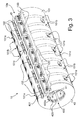
- FIG 3 is a perspective view of a portion of a cylinder body 10 according to one embodiment of the invention.
- a common shaft member has been omitted in this Figure, which common shaft member is illustrated in Figures 6a and 6b and will be discussed separately in the following description.
- the cylinder body 10 exhibits an essentially cylindrical outer shape with the clearance 10a extending axially over a length of the cylinder body 10.
- a cover plate 101 is provided on an outer circumference of the cylinder body 10.
- This cover plate 101 which is made of material exhibiting a low magnetic permeability is advantageously clamped at both extremities in the region of the clearance 10a.
- Clamping means 102, 103 are provided for this purpose, which clamping means are designed to secure the cover plate 101 in an adequate manner on the outer circumference of the cylinder body 10. More precisely, the cover plate 101 is clamped at one end by first clamping bars 102 and at the other end by second clamping bars 103. While this is not shown in detail, the second clamping bars 103 are designed to be displaceable on the cylinder body 10 so as to adjust the tension of the cover plate 101.
- the cover plate 101 is provided in this example with a plurality of rectangular openings 101 a.
- the positions of these openings 101 a is made to correspond to the positions of below-located magnetic-field-generating devices.
- the openings 101 a are as such optional and are preferable in case use is made of a particular type of magnetic-field-generating devices, such as those described in WO 2005/002866 which are to be disposed preferably in close proximity with the ink/varnish pattern containing the magnetic flakes to be oriented. With other types of magnetic-field-generating devices, one might omit the openings 101 a.
- a plurality of small openings 101 b visible on the upper part of Figure 3 are further provided in this example along a plurality of annular lines shown as dashed lines in the lower part of Figure 3 . As this will become apparent in the following, these openings 101 b communicate with a plurality of suction outlets located below the cover plate 101 and designed to permit aspiration of the processed sheet against the circumference of the cylinder body 10.
- Figure 4 is a view of part of the cylinder body 10 illustrated in Figure 3 without the cover plate 101.
- the cylinder body 10 comprises a plurality of annular supporting rings 40 distributed axially along the axis of rotation of the cylinder body 10.
- five identical annular supporting rings 40 are provided.
- An additional ring 45 is provided at the outermost right extremity of the cylinder body 10. This additional ring 45 essentially fulfils the function of supporting the right-hand side of the cover plate 101 shown in Figure 3 and provide symmetry to the overall cylinder body 10.
- Each annular supporting ring 40 is preferably provided with a peripheral mounting groove 40a and a pair of peripheral supporting shoulders 40b extending on each side of the annular mounting groove 40a.
- a plurality of supporting members 50 are mounted on the peripheral mounting groove 40a, which supporting members 50 are designed to receive a corresponding magnetic-field-inducing element (not shown).
- FIG. 5 is a schematic illustration of the said supporting members 50 according to a possible mounting configuration about the axis of rotation O of the cylinder body 10.
- all the other elements of the cylinder body 10 have been omitted so as to show all the supporting members 50 in their mounting positions.
- eight supporting members 50 are provided on each annular supporting ring 40, thus totalling to forty supporting members 50, each designed to form a corresponding magnetic-field-generating device for cooperation with a corresponding one of forty different locations on the sheets being processed.
- the resulting cylinder body is adapted for cooperation with sheets on the surface of which an array of forty magnetic-flakes-containing patterns arranged in a matrix of five columns and eight rows has been printed. Such arrangement is obviously purely illustrative and other arrangements might be envisaged.
- peripheral supporting shoulders 40b have a diameter such that the supporting members 50 (and accordingly the magnetic-field-generating devices as well) are almost completely enclosed between the supporting shoulders 40b.
- the supporting shoulders 40b are designed to provide a support on each side of the magnetic-field-generating devices, along the axis of rotation of the cylinder body 10.
- the peripheral mounting groove 40a preferably exhibits an inverted-T shape for insertion of the supporting members 50.
- Each supporting member 50 exhibits a corresponding T-shape matching that of the peripheral mounting groove 40a.
- each supporting member 50 is preferably provided with its own clamping element 51 (visible in Figures 5 , 7a , 8b , 9 and 10 ) adapted for cooperation with the peripheral mounting groove 40a of the annular supporting rings 40 for securing the magnetic-field-generating devices in place at any desired position along the peripheral mounting groove 40a. In this way, each magnetic-field-generating device can be adjusted freely along the circumference of the annular supporting rings 40, independently of the other magnetic-field-generating devices disposed on the same annular supporting ring 40.
- Figures 6a and 6b are two views illustrating the common shaft member 20 which forms the remainder of the cylinder body 10 according to this first embodiment.
- the annular supporting rings 40 discussed above (as well as the additional ring 45) are mounted on this common shaft member 20 by way of their central opening 400 visible in Figures 3 and 4 .
- each ring 40 (and 45) comprises an inner mounting groove 400a extending parallel to the axis of rotation O of the cylinder body 10.
- This inner mounting groove 400a is designed to enable mounting on the common shaft member 20 at a determined angular position about the common shaft member 20.
- a mounting bar (not shown) is secured to a longitudinal portion 20a of the common shaft member 20, which mounting bar cooperates with the inner mounting grooves 400a of the annular supporting rings 40. In this way, each annular supporting ring 40 is precisely positioned with respect to the common shaft member 20 and according to a same common angular reference position.
- the supporting members 50 and annular supporting rings 40 are preferably made of aluminium, or any other material exhibiting a low magnetic permeability.
- the common shaft member 20 is preferably provided with a plurality of suction apertures 200 distributed axially and circumferentially on the outer circumference of the common shaft member 20. These suction apertures 200 are meant to communicate with corresponding suction outlets (to be discussed hereinafter) provided on the annular supporting rings 40.
- each suction aperture 200 is advantageously designed as a threaded hole enabling selective closure thereof by means of corresponding plug elements, namely screwable elements in this case. This enables to selectively close unused apertures 200, namely apertures 200 which do not communicate with corresponding outlets of the annular supporting rings 40, i.e. the apertures 200 located between the annular supporting rings 40.
- the common shaft member 20 is provided with a plurality of independent suction channels 210 extending axially along the inside of the common shaft member 20.
- Each suction channel 210 communicates with a corresponding set of axially-distributed suction apertures 200 of the common shaft member 20.
- five suction channels 210 are provided, each channel 210 communicating with a corresponding set of apertures 200 (five rows of apertures 200 being provided on the circumference of the common shaft member 20).
- FIGs 7a and 7b are two perspective views of one annular supporting ring 40 taken from two different angles. As is visible on these Figures (and in Figures 3 and 4 as well), each annular supporting ring 40 exhibits a generally annular shape interrupted by a radial opening slit 401. This radial opening slit 401 enables a slight elastic deformation of the annular supporting ring 40 in the circumferential direction so as to facilitate mounting and adjustment of the position of the supporting ring 40 on the common shaft member 20.
- each annular supporting ring 40 is freely adjustable along the axis of the common shaft member 20, independently of the other annular supporting rings 40.
- FIGs 7a and 7b further show that each annular supporting ring 40 comprises a plurality of suction outlets 420 (also visible in Figures 3 and 4 ) opening in the inner opening 400 of the annular supporting ring 40. These suction outlets 420 communication with corresponding suction outlets 425 (also visible in Figure 4 ) opening on the outer circumference of the annular supporting ring 40.
- suction outlets 420, 425 are designed to cooperate with the suction apertures 200 provided on the common shaft member 20.
- independent suction chambers 41 are provided on the inner side of the annular supporting ring 40.
- Such independent suction chambers 41 are better visible in Figures 8a , 8b , 8c which are perspective views illustrating cross-sections of the annular supporting ring taken along three different planes perpendicular to the axis of rotation of the annular supporting ring 40.
- the cross-section are taken through the peripheral mounting groove 40a, while, in Figure 8c , the cross-section is taken through one of the peripheral supporting shoulders 40b.
- each independent suction chamber 41 is provided on the inner side of the annular supporting ring.
- a corresponding set of suction outlets 420 is provided which communicate with the suction outlets 425 on the outer circumference of the annular supporting ring as illustrated in Figure 8c .
- Each suction chamber 41 is designed to cooperate with a corresponding one of the five sets of axially-distributed suction apertures 200 provided along the outer circumference of the common shaft member 20 illustrated in Figures 6a, 6b .
- each suction chamber 41 communicates with a corresponding one of the five suction channels 210 provided in the common shaft member 210 via the suction apertures 200.
- This configuration permits to apply suction to only part of the circumference of each annular supporting ring 40, and thus to a corresponding part of the circumference of the cylinder body 10.
- each suction channel 210 of the common shaft member 20 communicates with suction outlets 425 on the circumference of the annular supporting rings 40 (via the corresponding suction apertures 200, suction chambers 41 and suction outlets 420) and enables application of suction to sectors of the circumference of the cylinder body 10 of approximately 60° each.
- one or two suction channels 210 might be active at a same time to draw a corresponding portion of the surface of the sheet being processed against the outer circumference of the cylinder body 10.
- the suction means disclosed hereinabove could furthermore be operated to briefly blow air to ease separation of the sheet being processed with the corresponding part of the circumference of the cylinder body 10.
- the supporting members 50 are inserted along the peripheral mounting groove 40a of the annular supporting rings 40, as for instance illustrated in Figures 8a and 8b .
- Each supporting member 50 is designed so as to be allowed to slide along the peripheral mounting groove 40a to adjust a circumferential position thereof. Once positioned, each supporting member 50 can be secured in place by means of a clamping element 51, as shown in Figure 8b and 9 .
- the clamping element 51 is shaped as a foot element disposed at the bottom of the supporting member 50 so as to cooperate with the peripheral mounting groove 40a of the annular supporting ring 40.
- a pair of threaded securing elements 52 cooperating with the clamping element 51 is provided in two through holes 50b of the supporting member 50, each threaded securing element 52 being accessible from the outer circumference using an adequate tool inserted in the corresponding through hole 50b.
- Each supporting element 50 can thus be secured in place by acting on the threaded securing elements 52 so that the clamping element 51 is urged towards the peripheral mounting groove 40a of the annular supporting ring 40.
- each supporting member 50 can be released from its position by releasing the clamping pressure exerted by the clamping element 51.
- openings 101 c enabling access to the through holes 50b of the supporting elements 50 are further provided next to the rectangular openings 101 a so as to permit fine adjustment of the position of each supporting element 50, if necessary, after the cover plate 101 is mounted.
- Figure 10 is an exploded perspective view of the supporting member 50 with its clamping element 51 and threaded securing elements 52. Also shown in Figure 10 for the purpose of illustration is a magnet-field-inducing element 60 that is placed in a corresponding opening 50a of the supporting member 50.
- the magnet-field-inducing element 60 can be as simple as a permanent magnet as illustrated in Figure 4 of International application WO 2005/000585 or a device comprising a body of permanent magnetic material the surface of which is engraved to cause perturbations of its magnetic field as discussed in International application WO 2005/002866 .
- the magnet-field-generating devices can be any type of device susceptible of producing a magnetic field capable of orienting the magnetic flakes contained in the ink/varnish patterns applied on the substrate to be processed.
- cover plate is only preferred.
- the cover plate could be replaced by intermediate supporting discs placed in the gaps between the annular supporting rings.
- silk-screen printing is a preferred printing process for applying the ink/varnish patterns contained the magnetic flakes to be oriented
- other printing process might be envisaged, such as the intaglio printing process as discussed in European patent application EP 1 650 042 .
- the cylinder body of the present invention can be used in printing presses other than silk-screen printing presses.
Landscapes
- Engineering & Computer Science (AREA)
- Mechanical Engineering (AREA)
- Screen Printers (AREA)
- Credit Cards Or The Like (AREA)
- Coating Apparatus (AREA)
- Inks, Pencil-Leads, Or Crayons (AREA)
- Printing Methods (AREA)
- Rotary Presses (AREA)
- Paints Or Removers (AREA)
- Soft Magnetic Materials (AREA)
- Manufacturing Of Magnetic Record Carriers (AREA)
Priority Applications (1)
| Application Number | Priority Date | Filing Date | Title |
|---|---|---|---|
| EP10165384A EP2221177B1 (de) | 2007-02-20 | 2008-02-19 | Zylinderkörper zur Ausrichtung von Magnetspänen eines auf einem blatt- oder bahnförmigen Substrat aufgetragenen Tinten- oder Lackbindemittels |
Applications Claiming Priority (3)
| Application Number | Priority Date | Filing Date | Title |
|---|---|---|---|
| EP07102749A EP1961559A1 (de) | 2007-02-20 | 2007-02-20 | Zylinderkörper zur Ausrichtung von Magnetspänen eines auf einem blatt- oder bahnförmigen Substrat aufgetragenen Tinten- oder Lackbindemittels |
| EP10165384A EP2221177B1 (de) | 2007-02-20 | 2008-02-19 | Zylinderkörper zur Ausrichtung von Magnetspänen eines auf einem blatt- oder bahnförmigen Substrat aufgetragenen Tinten- oder Lackbindemittels |
| EP08710085A EP2114678B1 (de) | 2007-02-20 | 2008-02-19 | Zylinderkörper zur ausrichtung von magnetspänen, die in einem auf einem blatt- oder bahnförmigen substrat aufgetragenen tinten- oder lackbindemittel enthalten sind |
Related Parent Applications (2)
| Application Number | Title | Priority Date | Filing Date |
|---|---|---|---|
| EP08710085A Division EP2114678B1 (de) | 2007-02-20 | 2008-02-19 | Zylinderkörper zur ausrichtung von magnetspänen, die in einem auf einem blatt- oder bahnförmigen substrat aufgetragenen tinten- oder lackbindemittel enthalten sind |
| EP08710085.5 Division | 2008-02-19 |
Publications (2)
| Publication Number | Publication Date |
|---|---|
| EP2221177A1 true EP2221177A1 (de) | 2010-08-25 |
| EP2221177B1 EP2221177B1 (de) | 2012-08-22 |
Family
ID=38283203
Family Applications (3)
| Application Number | Title | Priority Date | Filing Date |
|---|---|---|---|
| EP07102749A Withdrawn EP1961559A1 (de) | 2007-02-20 | 2007-02-20 | Zylinderkörper zur Ausrichtung von Magnetspänen eines auf einem blatt- oder bahnförmigen Substrat aufgetragenen Tinten- oder Lackbindemittels |
| EP10165384A Active EP2221177B1 (de) | 2007-02-20 | 2008-02-19 | Zylinderkörper zur Ausrichtung von Magnetspänen eines auf einem blatt- oder bahnförmigen Substrat aufgetragenen Tinten- oder Lackbindemittels |
| EP08710085A Active EP2114678B1 (de) | 2007-02-20 | 2008-02-19 | Zylinderkörper zur ausrichtung von magnetspänen, die in einem auf einem blatt- oder bahnförmigen substrat aufgetragenen tinten- oder lackbindemittel enthalten sind |
Family Applications Before (1)
| Application Number | Title | Priority Date | Filing Date |
|---|---|---|---|
| EP07102749A Withdrawn EP1961559A1 (de) | 2007-02-20 | 2007-02-20 | Zylinderkörper zur Ausrichtung von Magnetspänen eines auf einem blatt- oder bahnförmigen Substrat aufgetragenen Tinten- oder Lackbindemittels |
Family Applications After (1)
| Application Number | Title | Priority Date | Filing Date |
|---|---|---|---|
| EP08710085A Active EP2114678B1 (de) | 2007-02-20 | 2008-02-19 | Zylinderkörper zur ausrichtung von magnetspänen, die in einem auf einem blatt- oder bahnförmigen substrat aufgetragenen tinten- oder lackbindemittel enthalten sind |
Country Status (13)
| Country | Link |
|---|---|
| US (2) | US8499687B2 (de) |
| EP (3) | EP1961559A1 (de) |
| JP (1) | JP5127842B2 (de) |
| KR (1) | KR101422228B1 (de) |
| CN (1) | CN101631680B (de) |
| AT (1) | ATE516145T1 (de) |
| AU (1) | AU2008218546B2 (de) |
| BR (1) | BRPI0807748B1 (de) |
| CA (1) | CA2677034C (de) |
| ES (2) | ES2367857T3 (de) |
| RU (1) | RU2459709C2 (de) |
| WO (1) | WO2008102303A2 (de) |
| ZA (1) | ZA200905794B (de) |
Cited By (1)
| Publication number | Priority date | Publication date | Assignee | Title |
|---|---|---|---|---|
| CN107107605A (zh) * | 2014-12-22 | 2017-08-29 | 柯尼格及包尔公开股份有限公司 | 用于丝网印刷机的刮刀装置以及用于运行刮刀装置的方法 |
Families Citing this family (56)
| Publication number | Priority date | Publication date | Assignee | Title |
|---|---|---|---|---|
| EP1990208A1 (de) * | 2007-05-10 | 2008-11-12 | Kba-Giori S.A. | Vorrichtung und Verfahren zum magnetischen Übertragen von Markierungen auf eine auf ein Substrat aufgetragene Beschichtungszusammensetzung |
| EP2138437A1 (de) | 2008-06-27 | 2009-12-30 | Kba-Giori S.A. | Inspektionssystem zur Inspektion der Qualität von Druckbögen |
| TWI487626B (zh) * | 2008-12-10 | 2015-06-11 | Sicpa Holding Sa | 用於磁性取向及印刷的裝置及製程 |
| GB201001603D0 (en) * | 2010-02-01 | 2010-03-17 | Rue De Int Ltd | Security elements, and methods and apparatus for their manufacture |
| CN102267277B (zh) * | 2010-06-03 | 2014-11-26 | 北京中钞锡克拜安全油墨有限公司 | 磁性定向和印刷 |
| TWI587104B (zh) * | 2010-09-24 | 2017-06-11 | 西克帕控股有限公司 | 用於產生磁感應視覺效果之裝置、系統和方法 |
| EP2845732B1 (de) | 2010-09-24 | 2017-03-22 | KBA-NotaSys SA | Bogendruckmaschine und Verfahren zur Ausrichtung von Magnetspänen in einer Tinte oder einem Lackmedium zum Auftragen auf ein bogenähnliches Substrat |
| FR2986181B1 (fr) * | 2012-01-27 | 2014-02-21 | Oreal | Procede de realisation d'un decor sur un materiau support permettant la realisation d'etuis pour l'emballage d'un produit cosmetique |
| EP2637396A1 (de) | 2012-03-07 | 2013-09-11 | KBA-NotaSys SA | Verfahren zur Überprüfung der Herstellbarkeit eines zusammengestelltes Sicherheitsdesigns eines Sicherheitsdokumentes auf einer Druckstrasse, und digitale Computerumgebung zur Umsetzung davon |
| CN103386805B (zh) * | 2012-05-09 | 2015-01-21 | 中国人民银行印制科学技术研究所 | 磁定向滚筒 |
| CN103547454B (zh) * | 2012-05-09 | 2016-06-01 | 中国人民银行印制科学技术研究所 | 一种联合印刷装置 |
| FR2994890B1 (fr) | 2012-09-04 | 2014-09-12 | Oberthur Fiduciaire Sas | Cylindre de transfert de feuilles et ensemble constitue d'une juxtaposition de tels cylindres |
| CN103171252B (zh) * | 2013-03-29 | 2014-12-03 | 中钞油墨有限公司 | 平板丝网印刷机上的磁定位装置 |
| CN103192591B (zh) * | 2013-04-10 | 2015-10-21 | 中国人民银行印制科学技术研究所 | 磁定向滚筒及印刷机 |
| CN103448361B (zh) * | 2013-08-26 | 2015-06-17 | 惠州市华阳光学技术有限公司 | 用于磁性颜料印刷的磁定向装置及印刷装置 |
| DE102013018254A1 (de) * | 2013-10-30 | 2015-04-30 | Giesecke & Devrient Gmbh | Verfahren zur Herstellung eines Sicherheitselements |
| WO2015082344A1 (en) | 2013-12-04 | 2015-06-11 | Sicpa Holding Sa | Devices for producing optical effect layers |
| EP2902210A1 (de) | 2014-02-04 | 2015-08-05 | KBA-NotaSys SA | Mehrfarbenhochdruckpresse mit Nummerierzylindern und einer zusätzlichen Druckeinheit |
| AU2015306179A1 (en) * | 2014-08-22 | 2016-12-22 | Sicpa Holding Sa | Apparatus and method for producing optical effect layers |
| JP6616823B2 (ja) | 2014-08-26 | 2019-12-04 | カーベーアー−ノタシ ソシエテ アノニム | 複合印刷機 |
| KR20170052683A (ko) | 2014-09-12 | 2017-05-12 | 케이비에이-노타시스 에스에이 | 결합된 인쇄기 |
| EP3015266A1 (de) | 2014-10-30 | 2016-05-04 | KBA-NotaSys SA | Druckmaschine mit einer Einheit zum magnetischen Ausrichten und einer bewegbaren Trockner- bzw. Aushärtungseinheit |
| RU2605401C2 (ru) * | 2014-11-19 | 2016-12-20 | Федеральное государственное бюджетное учреждение науки Институт физической химии и электрохимии им. А.Н. Фрумкина Российской академии наук (ИФХЭ РАН) | Способ придания супергидрофобных свойств поверхности металла |
| CN104494294A (zh) * | 2014-11-26 | 2015-04-08 | 广东乐佳印刷有限公司 | 一种磁性油墨的方环状定向装置和方法 |
| CN105034570B (zh) * | 2015-09-10 | 2017-10-17 | 惠州市华阳光学技术有限公司 | 一种磁性印刷品的制造设备 |
| CN106142818B (zh) * | 2016-06-28 | 2018-10-02 | 上海紫明印刷机械有限公司 | 磁性定像凹印机 |
| CN114148115B (zh) | 2016-08-31 | 2024-06-14 | 唯亚威通讯技术有限公司 | 具有成角度的反射段的物品 |
| CN106274033A (zh) | 2016-10-12 | 2017-01-04 | 京东方科技集团股份有限公司 | 一种印刷机 |
| US10357991B2 (en) | 2016-12-19 | 2019-07-23 | Viavi Solutions Inc. | Security ink based security feature |
| EP3576888B1 (de) * | 2017-01-31 | 2021-03-31 | Sicpa Holding Sa | Vorrichtungen und verfahren zur herstellung von schichten mit optischem effekt |
| CN107199767B (zh) * | 2017-06-07 | 2019-04-16 | 中国人民银行印制科学技术研究所 | 一种防伪元件的印刷装置及印刷方法 |
| TWI794359B (zh) | 2018-01-17 | 2023-03-01 | 瑞士商西克帕控股有限公司 | 用於生產光學效應層之製程 |
| DE102018205882B4 (de) | 2018-04-18 | 2021-08-05 | Koenig & Bauer Ag | Vorrichtung und Maschine zum Ausrichten von magnetischen oder magnetisierbaren Partikeln auf einem bahn- oder bogenförmigen Substrat |
| DE102018205885B4 (de) | 2018-04-18 | 2021-05-20 | Koenig & Bauer Ag | Zylinder, Vorrichtung und Maschine zum Ausrichten von magnetischen oder magnetisierbaren Partikeln auf einem bahn- oder bogenförmigen Substrat |
| WO2019201481A1 (de) | 2018-04-18 | 2019-10-24 | Koenig & Bauer Ag | Vorrichtungen, maschine sowie verfahren zum auftragen und ausrichten von magnetischen oder magnetisierbaren partikeln auf einem bahn- oder bogenförmigen substrat |
| DE102018205883A1 (de) | 2018-04-18 | 2019-10-24 | Koenig & Bauer Ag | Vorrichtung und Maschine zum Ausrichten von magnetischen oder magnetisierbaren Partikeln auf einem bahn- oder bogenförmigen Substrat |
| PT3826852T (pt) * | 2018-07-25 | 2022-09-06 | Koenig & Bauer Ag | Dispositivos para alinhar partículas magnéticas ou magnetizáveis, bem como máquina para gerar elementos de imagem variáveis visualmente |
| DE102018127936A1 (de) * | 2018-11-08 | 2020-05-14 | Koenig & Bauer Ag | Vorrichtung, Druckmaschine und Verfahren zur Herstellung eines Sicherheitselementes auf einem Substrat |
| CN110228281B (zh) * | 2019-07-09 | 2024-05-07 | 嘉善杭运制版有限公司 | 防凹陷圆网版辊印刷机构 |
| AU2021279119A1 (en) | 2020-05-26 | 2023-02-02 | Sicpa Holding Sa | Magnetic assemblies and methods for producing optical effect layers comprising oriented platelet-shaped magnetic or magnetizable pigment particles |
| CN116075432B (zh) * | 2020-10-01 | 2025-07-04 | 柯尼格及包尔公开股份有限公司 | 用于生成光学可变图元的机器 |
| DE102021110864B4 (de) | 2021-04-28 | 2023-03-02 | Koenig & Bauer Ag | Vorrichtung zum Ausrichten von magnetischen oder magnetisierbaren Partikeln sowie Maschine zur Erzeugung optisch variabler Bildelemente |
| EP4355585A4 (de) | 2021-06-14 | 2025-05-07 | Viavi Solutions Inc. | Optisches sicherheitselement |
| DE102022114900B4 (de) * | 2022-06-14 | 2025-03-27 | Koenig & Bauer Ag | Zylinder mit mehreren eine Anzahl von Magnetelementen in Umfangsrichtung hintereinander tragendenden Tragelementen sowie Maschine zur Erzeugung optisch variabler Bildelemente |
| JP7630051B1 (ja) | 2022-04-13 | 2025-02-14 | ケーニッヒ ウント バウアー アー・ゲー | 磁性のまたは磁化可能な粒子を方向付けるシリンダ、磁石要素をシリンダに組み付けるかつ/または位置決めするシステムおよび光学的可変の画像要素を生成する機械 |
| DE102022109038B3 (de) | 2022-04-13 | 2023-03-02 | Koenig & Bauer Ag | Vorrichtung zum Ausrichten von magnetischen oder magnetisierbaren Partikeln sowie Maschine zur Erzeugung optisch variabler Bildelemente |
| DE102022109035A1 (de) * | 2022-04-13 | 2023-10-19 | Koenig & Bauer Ag | Zylinder mit einer Anzahl von in axialer Richtung nebeneinander angeordneter Gruppen von in Umfangsrichtung hintereinander angeordneten Magnetelementen sowie Vorrichtung zur Montage und/oder Positionierung von Magnetelementen an einem solchen Zylinder |
| DE102022109034B3 (de) | 2022-04-13 | 2023-03-02 | Koenig & Bauer Ag | Vorrichtung zum Ausrichten von magnetischen oder magnetisierbaren Partikeln sowie Maschine zur Erzeugung optisch variabler Bildelemente |
| MX2024011138A (es) | 2022-04-13 | 2024-09-19 | Koenig & Bauer Ag | Cilindro para la alineacion de particulas magneticas o magnetizables contenidas en un agente de revestimiento en un sustrato y una maquina para la generacion de elementos de imagen opticamente variable. |
| DE102022109036A1 (de) | 2022-04-13 | 2023-10-19 | Koenig & Bauer Ag | Vorrichtung zum Ausrichten von magnetischen oder magnetisierbaren Partikeln sowie Maschine zur Erzeugung optisch variabler Bildelemente |
| DE102022115536A1 (de) * | 2022-06-22 | 2023-12-28 | Koenig & Bauer Ag | Druckeinheit mit Ausrichteinrichtung, Non Impact Druckstelle sowie Aushärteeinrichtung |
| DE102022115535B4 (de) * | 2022-06-22 | 2026-03-05 | Koenig & Bauer Ag | Druckeinheit mit zwei Basismodulen und Non Impact Druckstelle |
| DE102022115533A1 (de) * | 2022-06-22 | 2023-12-28 | Koenig & Bauer Ag | Druckeinheit mit Ausrichteinrichtung, Non Impact Druckstelle sowie Aushärteeinrichtung |
| DE102022127807A1 (de) * | 2022-10-21 | 2024-05-02 | Koenig & Bauer Ag | Zylinder für eine bogenbe- und/oder verarbeitenden Maschine mit Saugluftöffnungen sowie Maschine zur Be- und/oder Verarbeitung bogenförmigen Substrates mit einem solchen Zylinder |
| FR3142281B1 (fr) * | 2022-11-18 | 2025-10-24 | Oberthur Fiduciaire Sas | Dispositif d’aimantation, cylindre et machine associés |
| DE102024111527A1 (de) * | 2024-04-24 | 2025-10-30 | Koenig & Bauer Ag | Vorrichtung zum Ausrichten von magnetischen oder magnetisierbaren Partikeln |
Citations (18)
| Publication number | Priority date | Publication date | Assignee | Title |
|---|---|---|---|---|
| US4838648A (en) | 1988-05-03 | 1989-06-13 | Optical Coating Laboratory, Inc. | Thin film structure having magnetic and color shifting properties |
| EP0686675A1 (de) | 1994-06-01 | 1995-12-13 | BASF Aktiengesellschaft | Magnetisierbare mehrfach beschichtete metallische Glanzpigmente |
| EP0723864A1 (de) | 1995-01-24 | 1996-07-31 | De La Rue Giori S.A. | Rotations-Siebdruckmaschine für den Bogendruck |
| EP0769376A1 (de) | 1995-10-20 | 1997-04-23 | De La Rue Giori S.A. | Bogendruckmaschine |
| WO1997029912A1 (de) | 1996-02-19 | 1997-08-21 | De La Rue Giori S.A. | Druckzylinder einer bogendruckmaschine |
| WO1997034767A1 (fr) | 1996-03-21 | 1997-09-25 | De La Rue Giori S.A. | Machine d'impression en serigraphie |
| WO2002073250A2 (en) | 2001-03-09 | 2002-09-19 | Sicpa Holding S.A. | Magnetic thin film interference device or pigment and method of making it, printing ink or coating composition, security document and use of such a magnetic thin film interference device |
| WO2003000801A2 (en) | 2001-04-27 | 2003-01-03 | Flex Products, Inc. | Multi-layered magnetic pigments and foils |
| WO2003093013A2 (de) | 2002-05-03 | 2003-11-13 | Kba-Giori S.A. | Siebdruckmaschine und siebzylinder |
| WO2004007095A2 (en) | 2002-07-15 | 2004-01-22 | Jds Uniphase Corporation | Method and apparatus for orienting magnetic flakes and image obtained by said method |
| WO2004007096A2 (en) | 2002-07-15 | 2004-01-22 | Jds Uniphase Corporation | Magnetic planarization of pigment flakes |
| WO2004096545A2 (de) | 2003-05-02 | 2004-11-11 | Kba-Giori S.A. | Farbtransport am siebdruckzylinder |
| WO2005000585A1 (fr) | 2003-06-30 | 2005-01-06 | Kba-Giori S.A. | Machine d'impression |
| WO2005002866A1 (en) | 2003-07-03 | 2005-01-13 | Sicpa Holding S.A. | Method and means for producing a magnetically induced design in a coating containing magnetic particles |
| WO2005095109A1 (en) | 2004-03-30 | 2005-10-13 | Kba-Giori S.A. | Printing process and machine |
| WO2005102699A1 (fr) | 2004-04-22 | 2005-11-03 | Kba-Giori S.A. | Dispositif de mise en place et de retrait d'une racle dans un cylindre d'impression en serigraphie |
| EP1650042A1 (de) | 2004-10-20 | 2006-04-26 | JDS Uniphase Corporation | Verfahren zum Ausrichten von Magnetteilchen in einer pastösen Farbe und bedrucken von optischen Effekte |
| EP1810756A2 (de) * | 2006-01-17 | 2007-07-25 | JDS Uniphase Corporation | Gerät für die Ausrichtung von Magnetspänen |
Family Cites Families (16)
| Publication number | Priority date | Publication date | Assignee | Title |
|---|---|---|---|---|
| US3721189A (en) * | 1971-06-28 | 1973-03-20 | Magna Graphics Corp | Magnetic print cylinder |
| US3742852A (en) * | 1971-10-01 | 1973-07-03 | Dayco Corp | Magnetic printing cylinder |
| US3897292A (en) * | 1972-08-18 | 1975-07-29 | Yamauchi Rubber Ind Co Ltd | Method of producing a printing magnetic saddle |
| US3873975A (en) * | 1973-05-02 | 1975-03-25 | Minnesota Mining & Mfg | System and method for authenticating and interrogating a magnetic record medium |
| GB1510105A (en) * | 1974-04-17 | 1978-05-10 | Emi Ltd | Printing |
| US4376330A (en) * | 1980-09-29 | 1983-03-15 | Kleinwefers Gmbh | Flexure-resistant calender roll |
| JPS57189343A (en) * | 1981-05-18 | 1982-11-20 | Hitachi Maxell Ltd | Manufacture of magnetic recording medium |
| JPH0657452B2 (ja) * | 1986-09-09 | 1994-08-03 | ア−ル・ア−ル・ドネリ−・アンド・サンズ・カンパニ− | 磁性シリンダの組立て方法 |
| JPH0189135U (de) * | 1987-12-02 | 1989-06-13 | ||
| NL9102074A (nl) * | 1991-12-12 | 1993-07-01 | Oce Nederland Bv | Drukinrichting. |
| RU2100209C1 (ru) * | 1992-12-14 | 1997-12-27 | Леонхард Курц ГмбХ унд Ко. | Способ переноса отпечатков с основы на подложку и устройство для его осуществления |
| JP3511761B2 (ja) * | 1995-10-20 | 2004-03-29 | 豊和工業株式会社 | ロッドレスシリンダ |
| JPH1021541A (ja) * | 1996-07-04 | 1998-01-23 | Berumateitsuku:Kk | 磁気記録媒体の変造防止方法およびその磁気記録媒体 |
| US5889544A (en) * | 1997-04-10 | 1999-03-30 | Eastman Kodak Company | Electrographic printer with multiple transfer electrodes |
| US7517578B2 (en) * | 2002-07-15 | 2009-04-14 | Jds Uniphase Corporation | Method and apparatus for orienting magnetic flakes |
| US7934451B2 (en) * | 2002-07-15 | 2011-05-03 | Jds Uniphase Corporation | Apparatus for orienting magnetic flakes |
-
2007
- 2007-02-20 EP EP07102749A patent/EP1961559A1/de not_active Withdrawn
-
2008
- 2008-02-19 EP EP10165384A patent/EP2221177B1/de active Active
- 2008-02-19 ZA ZA200905794A patent/ZA200905794B/xx unknown
- 2008-02-19 EP EP08710085A patent/EP2114678B1/de active Active
- 2008-02-19 RU RU2009132193/12A patent/RU2459709C2/ru active
- 2008-02-19 BR BRPI0807748A patent/BRPI0807748B1/pt active IP Right Grant
- 2008-02-19 CA CA2677034A patent/CA2677034C/en active Active
- 2008-02-19 JP JP2009550353A patent/JP5127842B2/ja active Active
- 2008-02-19 AT AT08710085T patent/ATE516145T1/de active
- 2008-02-19 US US12/527,580 patent/US8499687B2/en active Active
- 2008-02-19 CN CN2008800054358A patent/CN101631680B/zh active Active
- 2008-02-19 ES ES08710085T patent/ES2367857T3/es active Active
- 2008-02-19 KR KR1020097019198A patent/KR101422228B1/ko active Active
- 2008-02-19 ES ES10165384T patent/ES2392146T3/es active Active
- 2008-02-19 AU AU2008218546A patent/AU2008218546B2/en active Active
- 2008-02-19 WO PCT/IB2008/050592 patent/WO2008102303A2/en not_active Ceased
-
2013
- 2013-07-17 US US13/944,755 patent/US8813644B2/en active Active
Patent Citations (19)
| Publication number | Priority date | Publication date | Assignee | Title |
|---|---|---|---|---|
| US4838648A (en) | 1988-05-03 | 1989-06-13 | Optical Coating Laboratory, Inc. | Thin film structure having magnetic and color shifting properties |
| EP0686675A1 (de) | 1994-06-01 | 1995-12-13 | BASF Aktiengesellschaft | Magnetisierbare mehrfach beschichtete metallische Glanzpigmente |
| EP0723864A1 (de) | 1995-01-24 | 1996-07-31 | De La Rue Giori S.A. | Rotations-Siebdruckmaschine für den Bogendruck |
| EP0769376A1 (de) | 1995-10-20 | 1997-04-23 | De La Rue Giori S.A. | Bogendruckmaschine |
| WO1997029912A1 (de) | 1996-02-19 | 1997-08-21 | De La Rue Giori S.A. | Druckzylinder einer bogendruckmaschine |
| WO1997034767A1 (fr) | 1996-03-21 | 1997-09-25 | De La Rue Giori S.A. | Machine d'impression en serigraphie |
| WO2002073250A2 (en) | 2001-03-09 | 2002-09-19 | Sicpa Holding S.A. | Magnetic thin film interference device or pigment and method of making it, printing ink or coating composition, security document and use of such a magnetic thin film interference device |
| WO2003000801A2 (en) | 2001-04-27 | 2003-01-03 | Flex Products, Inc. | Multi-layered magnetic pigments and foils |
| WO2003093013A2 (de) | 2002-05-03 | 2003-11-13 | Kba-Giori S.A. | Siebdruckmaschine und siebzylinder |
| WO2004007095A2 (en) | 2002-07-15 | 2004-01-22 | Jds Uniphase Corporation | Method and apparatus for orienting magnetic flakes and image obtained by said method |
| WO2004007096A2 (en) | 2002-07-15 | 2004-01-22 | Jds Uniphase Corporation | Magnetic planarization of pigment flakes |
| US20040051297A1 (en) * | 2002-07-15 | 2004-03-18 | Flex Products, Inc., A Jds Uniphase Company | Method and apparatus for orienting magnetic flakes |
| WO2004096545A2 (de) | 2003-05-02 | 2004-11-11 | Kba-Giori S.A. | Farbtransport am siebdruckzylinder |
| WO2005000585A1 (fr) | 2003-06-30 | 2005-01-06 | Kba-Giori S.A. | Machine d'impression |
| WO2005002866A1 (en) | 2003-07-03 | 2005-01-13 | Sicpa Holding S.A. | Method and means for producing a magnetically induced design in a coating containing magnetic particles |
| WO2005095109A1 (en) | 2004-03-30 | 2005-10-13 | Kba-Giori S.A. | Printing process and machine |
| WO2005102699A1 (fr) | 2004-04-22 | 2005-11-03 | Kba-Giori S.A. | Dispositif de mise en place et de retrait d'une racle dans un cylindre d'impression en serigraphie |
| EP1650042A1 (de) | 2004-10-20 | 2006-04-26 | JDS Uniphase Corporation | Verfahren zum Ausrichten von Magnetteilchen in einer pastösen Farbe und bedrucken von optischen Effekte |
| EP1810756A2 (de) * | 2006-01-17 | 2007-07-25 | JDS Uniphase Corporation | Gerät für die Ausrichtung von Magnetspänen |
Cited By (2)
| Publication number | Priority date | Publication date | Assignee | Title |
|---|---|---|---|---|
| CN107107605A (zh) * | 2014-12-22 | 2017-08-29 | 柯尼格及包尔公开股份有限公司 | 用于丝网印刷机的刮刀装置以及用于运行刮刀装置的方法 |
| CN107107605B (zh) * | 2014-12-22 | 2020-05-05 | 柯尼格及包尔公开股份有限公司 | 具有至少一个印刷总成的有价证券印刷机以及用于运行刮刀装置的方法 |
Also Published As
| Publication number | Publication date |
|---|---|
| AU2008218546B2 (en) | 2013-08-22 |
| KR20090128415A (ko) | 2009-12-15 |
| AU2008218546A1 (en) | 2008-08-28 |
| EP2114678B1 (de) | 2011-07-13 |
| JP2010519080A (ja) | 2010-06-03 |
| CA2677034C (en) | 2015-08-04 |
| WO2008102303A2 (en) | 2008-08-28 |
| CN101631680B (zh) | 2012-06-06 |
| US8813644B2 (en) | 2014-08-26 |
| BRPI0807748B1 (pt) | 2018-12-04 |
| BRPI0807748A2 (pt) | 2014-06-17 |
| US20100170408A1 (en) | 2010-07-08 |
| RU2459709C2 (ru) | 2012-08-27 |
| CA2677034A1 (en) | 2008-08-28 |
| ZA200905794B (en) | 2010-10-27 |
| JP5127842B2 (ja) | 2013-01-23 |
| US20130298791A1 (en) | 2013-11-14 |
| EP2114678A2 (de) | 2009-11-11 |
| ES2367857T3 (es) | 2011-11-10 |
| EP2221177B1 (de) | 2012-08-22 |
| EP1961559A1 (de) | 2008-08-27 |
| ES2392146T3 (es) | 2012-12-05 |
| US8499687B2 (en) | 2013-08-06 |
| KR101422228B1 (ko) | 2014-07-30 |
| ATE516145T1 (de) | 2011-07-15 |
| CN101631680A (zh) | 2010-01-20 |
| WO2008102303A3 (en) | 2008-11-06 |
| RU2009132193A (ru) | 2011-03-27 |
Similar Documents
| Publication | Publication Date | Title |
|---|---|---|
| EP2221177B1 (de) | Zylinderkörper zur Ausrichtung von Magnetspänen eines auf einem blatt- oder bahnförmigen Substrat aufgetragenen Tinten- oder Lackbindemittels | |
| EP2433798B1 (de) | System und Verfahren zur Ausrichtung von Magnetspänen eines auf einem blatt- oder bahnförmigen Substrat aufgetragenen Tinten- oder Lackbindemittels | |
| KR19990082989A (ko) | 유가증권용 회전 인쇄기 | |
| EP3489029B1 (de) | Gedrucktes sicherheitselement mit einem regenbogenmerkmal und verfahren zur herstellung davon | |
| JPH11320817A5 (de) | ||
| JP7387941B2 (ja) | 光学的可変の画像要素を生成する機械 | |
| EP1737680B1 (de) | Stanzzylinder | |
| JP7496943B2 (ja) | 磁性のまたは磁化可能な粒子を方向付ける装置および光学的可変の画像要素を生成する機械 | |
| JP7547638B2 (ja) | スクリーン印刷ユニットとして形成され、2つのベースモジュールを備えるシート印刷ユニット | |
| JP2003521394A (ja) | シート処理用印刷機 | |
| US11926142B2 (en) | Sheet-fed printing unit configured as a screen printing unit | |
| EP2160291B1 (de) | Bandtuch für druckmaschine mit variabler abschaltung und druckverfahren | |
| CN118786036A (zh) | 具有排齐装置、无印版式印刷部位和固化装置的印刷单元 | |
| CN118786035A (zh) | 具有两个基座模块和无印版式印刷部位的印刷单元 | |
| GB2366243A (en) | A flexographic printing cartridge |
Legal Events
| Date | Code | Title | Description |
|---|---|---|---|
| PUAI | Public reference made under article 153(3) epc to a published international application that has entered the european phase |
Free format text: ORIGINAL CODE: 0009012 |
|
| AC | Divisional application: reference to earlier application |
Ref document number: 2114678 Country of ref document: EP Kind code of ref document: P |
|
| AK | Designated contracting states |
Kind code of ref document: A1 Designated state(s): AT BE BG CH CY CZ DE DK EE ES FI FR GB GR HR HU IE IS IT LI LT LU LV MC MT NL NO PL PT RO SE SI SK TR |
|
| AX | Request for extension of the european patent |
Extension state: AL BA MK RS |
|
| RAP1 | Party data changed (applicant data changed or rights of an application transferred) |
Owner name: KBA-NOTASYS SA |
|
| 17P | Request for examination filed |
Effective date: 20110215 |
|
| 17Q | First examination report despatched |
Effective date: 20110318 |
|
| REG | Reference to a national code |
Ref country code: DE Ref legal event code: R079 Ref document number: 602008018296 Country of ref document: DE Free format text: PREVIOUS MAIN CLASS: B41F0011020000 Ipc: B05D0003140000 |
|
| RIC1 | Information provided on ipc code assigned before grant |
Ipc: B41F 13/18 20060101ALI20120105BHEP Ipc: B41F 15/08 20060101ALI20120105BHEP Ipc: B41F 11/02 20060101ALI20120105BHEP Ipc: B05D 3/14 20060101AFI20120105BHEP Ipc: B05D 5/06 20060101ALI20120105BHEP |
|
| GRAP | Despatch of communication of intention to grant a patent |
Free format text: ORIGINAL CODE: EPIDOSNIGR1 |
|
| GRAS | Grant fee paid |
Free format text: ORIGINAL CODE: EPIDOSNIGR3 |
|
| GRAA | (expected) grant |
Free format text: ORIGINAL CODE: 0009210 |
|
| AC | Divisional application: reference to earlier application |
Ref document number: 2114678 Country of ref document: EP Kind code of ref document: P |
|
| AK | Designated contracting states |
Kind code of ref document: B1 Designated state(s): AT BE BG CH CY CZ DE DK EE ES FI FR GB GR HR HU IE IS IT LI LT LU LV MC MT NL NO PL PT RO SE SI SK TR |
|
| REG | Reference to a national code |
Ref country code: GB Ref legal event code: FG4D |
|
| REG | Reference to a national code |
Ref country code: CH Ref legal event code: EP |
|
| REG | Reference to a national code |
Ref country code: IE Ref legal event code: FG4D |
|
| REG | Reference to a national code |
Ref country code: AT Ref legal event code: REF Ref document number: 571653 Country of ref document: AT Kind code of ref document: T Effective date: 20120915 |
|
| REG | Reference to a national code |
Ref country code: DE Ref legal event code: R096 Ref document number: 602008018296 Country of ref document: DE Effective date: 20121018 |
|
| REG | Reference to a national code |
Ref country code: SE Ref legal event code: TRGR |
|
| REG | Reference to a national code |
Ref country code: NL Ref legal event code: T3 |
|
| REG | Reference to a national code |
Ref country code: ES Ref legal event code: FG2A Ref document number: 2392146 Country of ref document: ES Kind code of ref document: T3 Effective date: 20121205 |
|
| REG | Reference to a national code |
Ref country code: LT Ref legal event code: MG4D Effective date: 20120822 |
|
| PG25 | Lapsed in a contracting state [announced via postgrant information from national office to epo] |
Ref country code: IS Free format text: LAPSE BECAUSE OF FAILURE TO SUBMIT A TRANSLATION OF THE DESCRIPTION OR TO PAY THE FEE WITHIN THE PRESCRIBED TIME-LIMIT Effective date: 20121222 Ref country code: NO Free format text: LAPSE BECAUSE OF FAILURE TO SUBMIT A TRANSLATION OF THE DESCRIPTION OR TO PAY THE FEE WITHIN THE PRESCRIBED TIME-LIMIT Effective date: 20121122 Ref country code: LT Free format text: LAPSE BECAUSE OF FAILURE TO SUBMIT A TRANSLATION OF THE DESCRIPTION OR TO PAY THE FEE WITHIN THE PRESCRIBED TIME-LIMIT Effective date: 20120822 Ref country code: CY Free format text: LAPSE BECAUSE OF FAILURE TO SUBMIT A TRANSLATION OF THE DESCRIPTION OR TO PAY THE FEE WITHIN THE PRESCRIBED TIME-LIMIT Effective date: 20120822 Ref country code: HR Free format text: LAPSE BECAUSE OF FAILURE TO SUBMIT A TRANSLATION OF THE DESCRIPTION OR TO PAY THE FEE WITHIN THE PRESCRIBED TIME-LIMIT Effective date: 20120822 Ref country code: FI Free format text: LAPSE BECAUSE OF FAILURE TO SUBMIT A TRANSLATION OF THE DESCRIPTION OR TO PAY THE FEE WITHIN THE PRESCRIBED TIME-LIMIT Effective date: 20120822 |
|
| PG25 | Lapsed in a contracting state [announced via postgrant information from national office to epo] |
Ref country code: PT Free format text: LAPSE BECAUSE OF FAILURE TO SUBMIT A TRANSLATION OF THE DESCRIPTION OR TO PAY THE FEE WITHIN THE PRESCRIBED TIME-LIMIT Effective date: 20121224 Ref country code: SI Free format text: LAPSE BECAUSE OF FAILURE TO SUBMIT A TRANSLATION OF THE DESCRIPTION OR TO PAY THE FEE WITHIN THE PRESCRIBED TIME-LIMIT Effective date: 20120822 Ref country code: BE Free format text: LAPSE BECAUSE OF FAILURE TO SUBMIT A TRANSLATION OF THE DESCRIPTION OR TO PAY THE FEE WITHIN THE PRESCRIBED TIME-LIMIT Effective date: 20120822 Ref country code: GR Free format text: LAPSE BECAUSE OF FAILURE TO SUBMIT A TRANSLATION OF THE DESCRIPTION OR TO PAY THE FEE WITHIN THE PRESCRIBED TIME-LIMIT Effective date: 20121123 Ref country code: LV Free format text: LAPSE BECAUSE OF FAILURE TO SUBMIT A TRANSLATION OF THE DESCRIPTION OR TO PAY THE FEE WITHIN THE PRESCRIBED TIME-LIMIT Effective date: 20120822 |
|
| PG25 | Lapsed in a contracting state [announced via postgrant information from national office to epo] |
Ref country code: RO Free format text: LAPSE BECAUSE OF FAILURE TO SUBMIT A TRANSLATION OF THE DESCRIPTION OR TO PAY THE FEE WITHIN THE PRESCRIBED TIME-LIMIT Effective date: 20120822 Ref country code: EE Free format text: LAPSE BECAUSE OF FAILURE TO SUBMIT A TRANSLATION OF THE DESCRIPTION OR TO PAY THE FEE WITHIN THE PRESCRIBED TIME-LIMIT Effective date: 20120822 Ref country code: CZ Free format text: LAPSE BECAUSE OF FAILURE TO SUBMIT A TRANSLATION OF THE DESCRIPTION OR TO PAY THE FEE WITHIN THE PRESCRIBED TIME-LIMIT Effective date: 20120822 Ref country code: DK Free format text: LAPSE BECAUSE OF FAILURE TO SUBMIT A TRANSLATION OF THE DESCRIPTION OR TO PAY THE FEE WITHIN THE PRESCRIBED TIME-LIMIT Effective date: 20120822 |
|
| PG25 | Lapsed in a contracting state [announced via postgrant information from national office to epo] |
Ref country code: SK Free format text: LAPSE BECAUSE OF FAILURE TO SUBMIT A TRANSLATION OF THE DESCRIPTION OR TO PAY THE FEE WITHIN THE PRESCRIBED TIME-LIMIT Effective date: 20120822 Ref country code: PL Free format text: LAPSE BECAUSE OF FAILURE TO SUBMIT A TRANSLATION OF THE DESCRIPTION OR TO PAY THE FEE WITHIN THE PRESCRIBED TIME-LIMIT Effective date: 20120822 |
|
| PLBE | No opposition filed within time limit |
Free format text: ORIGINAL CODE: 0009261 |
|
| STAA | Information on the status of an ep patent application or granted ep patent |
Free format text: STATUS: NO OPPOSITION FILED WITHIN TIME LIMIT |
|
| 26N | No opposition filed |
Effective date: 20130523 |
|
| PG25 | Lapsed in a contracting state [announced via postgrant information from national office to epo] |
Ref country code: BG Free format text: LAPSE BECAUSE OF FAILURE TO SUBMIT A TRANSLATION OF THE DESCRIPTION OR TO PAY THE FEE WITHIN THE PRESCRIBED TIME-LIMIT Effective date: 20121122 |
|
| REG | Reference to a national code |
Ref country code: DE Ref legal event code: R097 Ref document number: 602008018296 Country of ref document: DE Effective date: 20130523 |
|
| PG25 | Lapsed in a contracting state [announced via postgrant information from national office to epo] |
Ref country code: MC Free format text: LAPSE BECAUSE OF NON-PAYMENT OF DUE FEES Effective date: 20130228 |
|
| REG | Reference to a national code |
Ref country code: IE Ref legal event code: MM4A |
|
| PG25 | Lapsed in a contracting state [announced via postgrant information from national office to epo] |
Ref country code: IE Free format text: LAPSE BECAUSE OF NON-PAYMENT OF DUE FEES Effective date: 20130219 |
|
| PG25 | Lapsed in a contracting state [announced via postgrant information from national office to epo] |
Ref country code: TR Free format text: LAPSE BECAUSE OF FAILURE TO SUBMIT A TRANSLATION OF THE DESCRIPTION OR TO PAY THE FEE WITHIN THE PRESCRIBED TIME-LIMIT Effective date: 20120822 |
|
| PG25 | Lapsed in a contracting state [announced via postgrant information from national office to epo] |
Ref country code: HU Free format text: LAPSE BECAUSE OF FAILURE TO SUBMIT A TRANSLATION OF THE DESCRIPTION OR TO PAY THE FEE WITHIN THE PRESCRIBED TIME-LIMIT; INVALID AB INITIO Effective date: 20080219 Ref country code: LU Free format text: LAPSE BECAUSE OF NON-PAYMENT OF DUE FEES Effective date: 20130219 |
|
| REG | Reference to a national code |
Ref country code: FR Ref legal event code: PLFP Year of fee payment: 9 |
|
| REG | Reference to a national code |
Ref country code: FR Ref legal event code: PLFP Year of fee payment: 10 |
|
| PGFP | Annual fee paid to national office [announced via postgrant information from national office to epo] |
Ref country code: NL Payment date: 20161230 Year of fee payment: 10 |
|
| REG | Reference to a national code |
Ref country code: FR Ref legal event code: PLFP Year of fee payment: 11 |
|
| REG | Reference to a national code |
Ref country code: NL Ref legal event code: MM Effective date: 20180301 |
|
| PG25 | Lapsed in a contracting state [announced via postgrant information from national office to epo] |
Ref country code: NL Free format text: LAPSE BECAUSE OF NON-PAYMENT OF DUE FEES Effective date: 20180301 |
|
| PGFP | Annual fee paid to national office [announced via postgrant information from national office to epo] |
Ref country code: CH Payment date: 20250301 Year of fee payment: 18 |
|
| PGFP | Annual fee paid to national office [announced via postgrant information from national office to epo] |
Ref country code: MT Payment date: 20250220 Year of fee payment: 18 |
|
| REG | Reference to a national code |
Ref country code: CH Ref legal event code: U11 Free format text: ST27 STATUS EVENT CODE: U-0-0-U10-U11 (AS PROVIDED BY THE NATIONAL OFFICE) Effective date: 20260301 |
|
| PGFP | Annual fee paid to national office [announced via postgrant information from national office to epo] |
Ref country code: SE Payment date: 20260228 Year of fee payment: 19 |
|
| PGFP | Annual fee paid to national office [announced via postgrant information from national office to epo] |
Ref country code: GB Payment date: 20260226 Year of fee payment: 19 |
|
| PGFP | Annual fee paid to national office [announced via postgrant information from national office to epo] |
Ref country code: ES Payment date: 20260302 Year of fee payment: 19 |
|
| PGFP | Annual fee paid to national office [announced via postgrant information from national office to epo] |
Ref country code: DE Payment date: 20260305 Year of fee payment: 19 |
|
| PGFP | Annual fee paid to national office [announced via postgrant information from national office to epo] |
Ref country code: AT Payment date: 20260223 Year of fee payment: 19 |
|
| PGFP | Annual fee paid to national office [announced via postgrant information from national office to epo] |
Ref country code: IT Payment date: 20260227 Year of fee payment: 19 |
|
| PGFP | Annual fee paid to national office [announced via postgrant information from national office to epo] |
Ref country code: FR Payment date: 20260225 Year of fee payment: 19 |