EP2221447A2 - Segments de retenue pour outil de fonds de puits - Google Patents
Segments de retenue pour outil de fonds de puits Download PDFInfo
- Publication number
- EP2221447A2 EP2221447A2 EP10153613A EP10153613A EP2221447A2 EP 2221447 A2 EP2221447 A2 EP 2221447A2 EP 10153613 A EP10153613 A EP 10153613A EP 10153613 A EP10153613 A EP 10153613A EP 2221447 A2 EP2221447 A2 EP 2221447A2
- Authority
- EP
- European Patent Office
- Prior art keywords
- slip
- cavities
- tool according
- well
- mandrel
- Prior art date
- Legal status (The legal status is an assumption and is not a legal conclusion. Google has not performed a legal analysis and makes no representation as to the accuracy of the status listed.)
- Granted
Links
- 238000007789 sealing Methods 0.000 claims description 4
- 230000000712 assembly Effects 0.000 abstract description 8
- 238000000429 assembly Methods 0.000 abstract description 8
- 239000000463 material Substances 0.000 description 9
- 239000002131 composite material Substances 0.000 description 5
- 238000005553 drilling Methods 0.000 description 3
- 239000004033 plastic Substances 0.000 description 3
- 229920003023 plastic Polymers 0.000 description 3
- 239000002002 slurry Substances 0.000 description 3
- 125000006850 spacer group Chemical group 0.000 description 3
- 229910000831 Steel Inorganic materials 0.000 description 2
- 230000000295 complement effect Effects 0.000 description 2
- 239000012530 fluid Substances 0.000 description 2
- 239000002184 metal Substances 0.000 description 2
- 229910052751 metal Inorganic materials 0.000 description 2
- 239000007769 metal material Substances 0.000 description 2
- 230000000717 retained effect Effects 0.000 description 2
- 239000010959 steel Substances 0.000 description 2
- 229910001018 Cast iron Inorganic materials 0.000 description 1
- 229920000459 Nitrile rubber Polymers 0.000 description 1
- 239000000853 adhesive Substances 0.000 description 1
- 230000001070 adhesive effect Effects 0.000 description 1
- 238000004873 anchoring Methods 0.000 description 1
- 230000015572 biosynthetic process Effects 0.000 description 1
- 239000004568 cement Substances 0.000 description 1
- 238000004891 communication Methods 0.000 description 1
- 238000010276 construction Methods 0.000 description 1
- 230000000694 effects Effects 0.000 description 1
- 229920001971 elastomer Polymers 0.000 description 1
- 239000011152 fibreglass Substances 0.000 description 1
- 238000004519 manufacturing process Methods 0.000 description 1
- 150000002739 metals Chemical class 0.000 description 1
- 238000000034 method Methods 0.000 description 1
- 238000003801 milling Methods 0.000 description 1
- 238000000465 moulding Methods 0.000 description 1
- 239000003129 oil well Substances 0.000 description 1
- ISWSIDIOOBJBQZ-UHFFFAOYSA-N phenol group Chemical group C1(=CC=CC=C1)O ISWSIDIOOBJBQZ-UHFFFAOYSA-N 0.000 description 1
- 230000002028 premature Effects 0.000 description 1
- UONOETXJSWQNOL-UHFFFAOYSA-N tungsten carbide Chemical compound [W+]#[C-] UONOETXJSWQNOL-UHFFFAOYSA-N 0.000 description 1
Images


Classifications
-
- E—FIXED CONSTRUCTIONS
- E21—EARTH OR ROCK DRILLING; MINING
- E21B—EARTH OR ROCK DRILLING; OBTAINING OIL, GAS, WATER, SOLUBLE OR MELTABLE MATERIALS OR A SLURRY OF MINERALS FROM WELLS
- E21B33/00—Sealing or packing boreholes or wells
- E21B33/10—Sealing or packing boreholes or wells in the borehole
- E21B33/12—Packers; Plugs
- E21B33/129—Packers; Plugs with mechanical slips for hooking into the casing
-
- E—FIXED CONSTRUCTIONS
- E21—EARTH OR ROCK DRILLING; MINING
- E21B—EARTH OR ROCK DRILLING; OBTAINING OIL, GAS, WATER, SOLUBLE OR MELTABLE MATERIALS OR A SLURRY OF MINERALS FROM WELLS
- E21B23/00—Apparatus for displacing, setting, locking, releasing or removing tools, packers or the like in boreholes or wells
- E21B23/04—Apparatus for displacing, setting, locking, releasing or removing tools, packers or the like in boreholes or wells operated by fluid means, e.g. actuated by explosion
- E21B23/0411—Apparatus for displacing, setting, locking, releasing or removing tools, packers or the like in boreholes or wells operated by fluid means, e.g. actuated by explosion specially adapted for anchoring tools or the like to the borehole wall or to well tube
Definitions
- Downhole tools for use in oil and gas wellbores often have drillable components made from metallic or non-metallic materials, such as soft steel, cast iron, engineering grade plastics, and composite materials.
- downhole tools In the drilling or reworking of oil wells, a great variety of downhole tools are used. For example, but not by way of limitation, it is often desirable to seal tubing or other pipe in the casing of the well, such as when it is desired to pump cement or other slurry down the tubing and force the slurry out into a formation. It thus becomes necessary to seal the tubing with respect to the well casing and to prevent the fluid pressure of the slurry from lifting the tubing out of the well. Downhole tools referred to as packers and bridge plugs are designed for these general purposes and are well known in the art of producing oil and gas.
- Bridge plugs isolate the portion of the well below the bridge plug from the portion thereabove. Bridge plugs therefore may experience a high differential pressure and must be capable of withstanding the pressure so that the bridge plug seals the well and does not move in the well after it has been set.
- Bridge plugs make use of metallic or non-metallic slip segments, or slips, that are initially retained in close proximity to a mandrel but are forced outwardly away from the mandrel of the tool upon the tool being set to engage a casing previously installed within an open wellbore.
- the slips are forced outwardly against the inside of the casing to secure the packer, or bridge plug as the case may be, so that the tool will not move relative to the casing when, for example, operations are being conducted for tests, to stimulate production of the well, or to plug all or a portion of the well.
- Cylindrically shaped inserts, or buttons may be placed in such slip segments, especially when the slip segments are made of a non-metallic material such as plastic composite material, to enhance the ability of the slip segments to engage the well casing.
- the buttons must be of sufficient hardness to be able to partially penetrate, or bite into, the surface of the well casing which is typically steel. However, especially in the case of downhole tools being constructed of materials that lend themselves to being easily drilled from the wellbore once a given operation involving the tool has been performed, the buttons must not be so hard or so tough to resist drilling or fouling of the cutting surfaces of the drilling bit or milling bit.
- the orientation of the slip buttons relative to the casing can also be a factor in the gripping ability of the slip segments.
- a downhole tool for use in a well which tool comprises a mandrel; a plurality of slip segments disposed about the mandrel, the slip segments comprising: a slip segment body, the slip segment body defining a plurality of cavities therein; and an insert disposed in at least one of the cavities, each of the cavities having a longitudinal central axis, the longitudinal central axis of each of said cavities being parallel to the longitudinal central axis of the other of the cavities.
- apparatus for anchoring a downhole tool in a well comprising: a plurality of slip segments disposed about a mandrel of the tool, the slip segments comprising: a slip segment body, the slip segment body defining a plurality of cavities therein; and an insert disposed in at least one of the cavities, each of the cavities having a longitudinal central axis, the longitudinal central axis of each of said cavities being parallel to the longitudinal central axis of the other of the cavities.
- a downhole tool for use in a well comprising: a mandrel; a plurality of slip segments disposed about the mandrel movable from an unset position to a set position in which the slip segments engage the well, the slip segments comprising: a slip segment body defining a plurality of cavities therein; and an insert affixed in at least one of the cavities, wherein the longitudinal axis of each of the cavities is oriented such that it lies in a vertical plane parallel to the vertical planes in which the longitudinal axes of the other cavities lie.
- a downhole tool for use in a well comprising: a mandrel; an expandable sealing element disposed about the mandrel for sealingly engaging the well; and a plurality of slip segments disposed about the mandrel for grippingly engaging the well, each slip segment comprising: a slip segment body defining an outer face; and a plurality of inserts extending outwardly from the outer face, wherein each insert in a slip segment body will engage the well at an angle of engagement different than the angle of engagement of other inserts in the slip segment body.
- a downhole tool has a mandrel and an expandable packer element disposed thereabout for sealingly engaging a well.
- Slip assemblies are positioned on the mandrel above and/or below the packer element to anchor the downhole tool in the well.
- Each slip assembly comprises a slip ring movable from an unset position to a set position in which the slip ring engages the well.
- the slip ring comprises a plurality of slip segments. Each slip segment is retained about the mandrel and is movable radially outwardly so that it will engage the well and anchor the tool in the well.
- a plurality of inserts, or buttons may be secured to the slip segments, and will extend outwardly from the outer surface thereof to grip casing in the well.
- the inserts are disposed in cavities which preferably are oriented such that the longitudinal central axis of each cavity in an individual slip segment is parallel to the longitudinal central axis of each of the other cavities in that slip segment.
- the longitudinal axis of each insert in an individual slip segment will thus be parallel to the longitudinal axis of each of the other inserts in that slip segment.
- a retaining ring is disposed about the slip ring to retain the slip ring about the mandrel, and may be received in grooves defined in the slip segments that comprise the slip ring.
- the retaining ring will hold the slip ring in an unset position, and will prevent the slip ring from prematurely moving outwardly to the set position in which the slip ring grippingly engages the casing to hold the tool in the well.
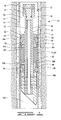
- FIG. 1 is a cross section of a downhole tool disposed in a well.
- FIG. 2 is an enlarged cross section of a slip segment of the current disclosure.
- FIG. 3 is a side view of a slip segment of the current disclosure.
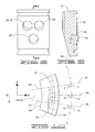
- FIG. 4 is a view of the forward face of the slip segment of FIG. 3 .
- FIG. 5 is a cross-sectional view from line 5-5 of FIG. 4 with an insert, or button installed.
- FIG. 6 is an end view of a slip segment of the current disclosure.
- FIG. 7 is a side view of a prior art slip segment.
- FIG. 8 is a view of the forward face of a prior art slip segment.
- FIG. 9 is a cross-sectional view taken from line 9-9 of FIG. 8 .
- FIG. 10 is an end view of a prior art slip segment.
- FIG. 1 shows well 10 comprising a wellbore 12 with a casing 14 cemented therein.
- Downhole tool 16 comprises a mandrel 18 with an outer surface 20 and an inner surface 22.
- the tool in FIG. 1 may generally be referred to as a bridge plug since downhole tool 16 has an optional plug 24 pinned within mandrel 18 by radially oriented pins 26.
- Plug 24 has a seal 28 located between plug 24 and mandrel 18.
- the overall tool structure would be suited for use as and referred to simply as a packer if plug 24 were not incorporated and fluid communication were allowed through the tool.
- Other components may be connected so that the packer, without plug 24 may be used, for example, as a frac plug.
- a spacer ring 30 is mounted to mandrel 18 with a pin 32.
- a slip assembly 34 is disposed about mandrel 18 and spacer ring 30 provides an abutment which serves to axially retain slip assembly 34.
- Downhole tool 16 has two slip assemblies 34, namely a first slip assembly and second slip assembly which are shown in the drawings and are designated in the drawings as first and second slip assemblies 34a and 34b for ease of reference. The slip assemblies will anchor downhole tool 16 in well 10.
- the structure of slip assemblies 34a and 34b is identical, and only the orientation and position on downhole tool 16 are different.
- Each slip assembly 34 includes a slip ring 36 and slip wedge 38 which is pinned into place with pins 40.
- Slip ring 36 is an expandable slip ring 36 which has a retaining ring 42 disposed in grooves 44. Retaining ring 42 will retain slip ring 36 in an unset position about mandrel 18 when downhole tool 16 is lowered into the well. Slip rings 36 may be moved or radially expanded from the unset to the set position which is seen in FIG. 1 in which the first and second slip rings 36 engage casing 14 to hold downhole tool 16 in the well. Retaining rings 42 will break as slip rings 36 expand radially outwardly.
- Slip rings 36 are comprised of a drillable material and may be, for example, a molded phenolic and have an outer surface 46. Slip rings 36 may be made from other drillable materials as well such as drillable metals, composites and engineering grade plastics. The remainder of the slip assembly and other components of the tool may likewise be made from drillable materials.
- a plurality of inserts or buttons 48 are secured to slip ring 36 by adhesive or by other means and extend radially outwardly from outer surface 46.
- the buttons may be cylindrically shaped, and are comprised of material of sufficient hardness to partially penetrate or bite into the well casing and may be comprised, for example, of tungsten carbide or other materials.
- the buttons may be, for example, like those described in U. S. Patent 5,984,007 . In the set position as shown in FIG. 1 , buttons 48 will engage or grip casing 14 to hold tool 16 in place.
- Each slip ring 36 is preferably comprised of a plurality of slip segments 50. Slip segments 50 are shown in cross section in FIG. 2 . Slip rings 36 may include, for example, six to eight slip segments 50 that encircle mandrel 18. Slip ring 36 may include more or less than six or eight segments, and the examples herein are non-limiting.
- a packer element assembly 60 which includes at least one expandable packer element 62 is positioned between slip wedges 38. Packer shoes 64 may provide axial support to the ends of packer element assembly 60.
- Retaining rings 42 are disposed about slip rings 36, and may be received in grooves 44.
- Retaining rings 42 are each comprised of a retaining band 68, and a dampener, or spring suppressor 70.
- Retaining band 68 can be used, if desired, without spring suppressor 70, in which case retaining ring 42 will simply comprise retaining band 68.
- Retaining band 68 may be made from a metal, or may be a composite, such as a fiberglass composite retaining band. The examples provided are not limiting, and retaining band 68 may comprise any material, preferably a drillable material, that will provide adequate strength to prevent premature breakage.
- Dampener 70 may be made from rubber, for example, a nitrile rubber. Other materials that will dampen or suppress the energy, or spring effect of retaining band 68 may be used. Dampener 70 is affixed to retaining band 68 by, for example, bonding, or molding.
- Retaining band 68 may be a ring-shaped band 68, and may have a rectangular cross section with outer surface 72.
- Outer surface 72 may comprise outer circumferential surface 74, inner circumferential surface 76, and side surfaces 78 and 80.
- Dampener 70 may be affixed to any or all of surfaces 74, 76, 78 and 80, and may, if desired, completely encapsulate retaining band 68.
- Slip segments 50 of the current disclosure are shown in FIGS. 2-6 .
- Slip segments 50 comprise a slip segment body 51 with first and second ends 82 and 84, which may be referred to as abutment end and free end 82 and 84, respectively.
- Slip segment body 51 has first and second sides 88 and 90, and a forward, or outer arcuate face 92.
- An arcuate inner surface 93 will preferably have topology complementary to outer surface 20 of mandrel 18.
- Buttons, or inserts 48 are secured to slip segment bodies 51 and extend outwardly from outer arcuate face 92. Inserts 48 are secured in cavities 94, which may include first, second and third cavities 96, 98 and 100. While the embodiment shown has three cavities and three inserts 48 in each slip segment body 51, it is understood that more or less cavities and inserts may be utilized. Cavities 96, 98 and 100 have longitudinal axes 101, identified as longitudinal axes 102, 104 and 106, respectively. Buttons 48 are preferably cylindrically shaped buttons with longitudinal central axis 108.
- Longitudinal central axes 102, 104 and 106 are parallel, and as such, the longitudinal central axis 108 of each of inserts 48 in a slip segment body 51 is parallel to the longitudinal central axis of the other axes 108 in that slip segment body 51.
- Longitudinal central axes 102, 104 and 106 will not intersect, and will not intersect the vertical plane in which any of longitudinal central axes 102, 104 and 106 lie.
- Vertical is the up-and-down direction as viewed in FIGS. 1 and 3 , and perpendicular to the plane of the page in the end view of FIG. 6 .
- Axis 106 will pass through a diametric center D of the arc defined by surface 92, but axes 102 and 104 will not pass therethrough.
- slip segment body 51 has a horizontal bisecting line 109 that rests in a vertical plane 112, perpendicular to the plane of the page as seen in FIG. 6 .
- Longitudinal central axis 106 is collinear with bisecting line 109 and as such also lies in vertical plane 112.
- Longitudinal central axes 102 and 104 also lie in vertical planes, which may be referred to as vertical planes 114 and 116. Longitudinal axes 102, 104 and 106 thus lie in parallel vertical planes, as do each of the axes 108 of the inserts 48 in a single slip segment 50.
- Each longitudinal axis of a cavity 94 in a slip segment body 51 is thus angularly displaced from a horizontal axis in one direction only, as shown in FIG. 3 , and may be described as such.
- each of longitudinal central axes 101 will be angled from a horizontal, or X axis in the vertical, or Y direction, but will lie in a vertical plane.
- Angle 117 may be between 10° and 20°, and may be approximately 15°.
- the angles provided are exemplary only, and are not limiting.
- the longitudinal axes 101 are not angled from the horizontal, or X axis in the transverse or Z direction.
- FIGS. 7-10 are representative of prior art slip segments which will be referred to as prior art slip segments 120 and show the distinction in the orientation of the prior art inserts, from the orientation of the buttons 48 in slip segments 50.
- Slip segments 120 comprise slip segment bodies 121 and have first and second ends 122 and 124, which may be referred to as abutment end and free end 122 and 124.
- An arcuate inner surface 126 will preferably have topology complementary to the outermost surface of the mandrel to which it is mounted.
- Slip segment body 121 has first and second sides 128 and 130, and has a forward, or outer arcuate face 132.
- a plurality of buttons, or inserts 134 are secured to slip segment 120, and extend externally outwardly from outer arcuate face 132. Inserts 134 are shaped substantially identically to inserts 48. Inserts 134 are secured in cavities 136 defined in slip segment body 121. Cavities 136 may be referred to as first, second and third cavities 138, 140 and 142, with longitudinal central axes 144, 146 and 148, respectively. Cavities 138, 140 and 142 are oriented so that longitudinal axes 144, 146 and 148 lie in intersecting vertical planes. When slip segments 120 are positioned vertically, as shown in FIG.
- each of longitudinal central axes 144, 146 and 148 are angled from a horizontal axis by an angle 149 which may be, for example, approximately 15°.
- longitudinal central axes 144 and 146 are angled in opposite directions from a horizontal axis, and thus will intersect the vertical plane 152 defined by a horizontal axis 150.
- Longitudinal central axes 144 and 146 lie in vertical planes 145 and 147 respectively.
- Horizontal axis 150 is collinear with longitudinal central axis 148.
- Longitudinal axis 148 will lie in plane 152 thus longitudinal central axes 144, 146 and 148 lie in intersecting vertical planes 145, 147 and 152.
- downhole tool 16 is deployed in well 10 using known deployment means such as for example jointed or coiled tubing. Downhole tool 16 will be in an unset position wherein tool 16 does not engage well 10. Thus, neither slip ring 36, nor packer element assembly 60 will engage casing 14 in the unset position. In the unset position, spacer ring 30, both of slip rings 36a and 36b and slip wedges 38a and 38b are all in an initial position about mandrel 18 and are positioned radially inwardly from the set position shown in FIG. 1 . When downhole tool 16 reaches a desired location in the well, each of slip rings 36a and 36b are moved radially outwardly to the set position shown in FIG. 1 , and tool 16 may be left in well 10. Downhole tool 16 separates well 10 into upper well portion 10a and lower portion 10b. The upper and lower portions 10a and 10b are isolated from one another by well tool 16 which in the embodiment shown is a bridge plug.
- well tool 16 which in the embodiment shown is a bridge plug.
- Retaining rings 42 will retain slip rings 36 in place about mandrel 18 in the unset position prior to being moved to the set position in FIG. 1 .
- Retaining rings 42 will break as slip rings 36a and 36b move radially outwardly to the set position.
- Slip rings 36 with slip segments 50, having cavities and inserts 48 as disclosed herein have exhibited greater gripping strength than slips with inserts oriented as in the prior art.
- Prior art slip segments exhibited the ability to hold a tool in the well with a pressure of approximately 9500 psi, which has a force equivalent of approximately 124,000 pounds (56,364 kg).
- Slip segments 50, with cavities and inserts 48 oriented as described herein, have been shown in tests to hold pressure of approximately 12,200 psi, which has a force equivalent of 160,000 pounds (72,727 kg) and is a greater than twenty percent increase.
- the data set forth herein was averaged from five tests for the prior art orientation, and five tests for the new orientation disclosed herein.
- each insert 48 will have an angle of engagement with the well that is different from the angle of engagement for the other of the inserts 48 in a slip segment 50.
- the angle of engagement B with the well is the angle between the longitudinal central axis of the cavity, and the collinear longitudinal axis of the insert in the cavity, and a tangent T to the well at the point of intersection between the well and the longitudinal central axis of the cavity.
- Angles B 1 , B 2 and B 3 shown in FIG. 6 at the point of intersection for tangents T 1 , T 2 and T 3 are not the same, as is the case in the prior art.
- the angle of engagement A with well 10 which is represented by a dashed line in FIG.
- each longitudinal central axis of a cavity in the prior art will thus intersect the diametric center D of the arc defined by the outer surface of the slip segment and angles of engagement A 1 , A 2 and A 3 are the same.
- the angles of engagement B which will be referred to as B 1 , B 2 and B 3 of slip segment body 51 are not the same, since the longitudinal central axis of each of the cavities do not intersect, or run through the diametric center D of the arc defined by the outer surface of the slip segment 50, as is the case with the prior art.
Landscapes
- Life Sciences & Earth Sciences (AREA)
- Engineering & Computer Science (AREA)
- Geology (AREA)
- Mining & Mineral Resources (AREA)
- Physics & Mathematics (AREA)
- Environmental & Geological Engineering (AREA)
- Fluid Mechanics (AREA)
- General Life Sciences & Earth Sciences (AREA)
- Geochemistry & Mineralogy (AREA)
- Earth Drilling (AREA)
Applications Claiming Priority (1)
| Application Number | Priority Date | Filing Date | Title |
|---|---|---|---|
| US12/388,025 US8047279B2 (en) | 2009-02-18 | 2009-02-18 | Slip segments for downhole tool |
Publications (3)
| Publication Number | Publication Date |
|---|---|
| EP2221447A2 true EP2221447A2 (fr) | 2010-08-25 |
| EP2221447A3 EP2221447A3 (fr) | 2012-05-30 |
| EP2221447B1 EP2221447B1 (fr) | 2017-01-18 |
Family
ID=42060613
Family Applications (1)
| Application Number | Title | Priority Date | Filing Date |
|---|---|---|---|
| EP10153613.4A Not-in-force EP2221447B1 (fr) | 2009-02-18 | 2010-02-15 | Segments de retenue pour outil de fonds de puits |
Country Status (3)
| Country | Link |
|---|---|
| US (1) | US8047279B2 (fr) |
| EP (1) | EP2221447B1 (fr) |
| CA (1) | CA2692114C (fr) |
Cited By (1)
| Publication number | Priority date | Publication date | Assignee | Title |
|---|---|---|---|---|
| US9228411B2 (en) | 2010-10-06 | 2016-01-05 | Packers Plus Energy Services Inc. | Wellbore packer back-up ring assembly, packer and method |
Families Citing this family (34)
| Publication number | Priority date | Publication date | Assignee | Title |
|---|---|---|---|---|
| US8408290B2 (en) * | 2009-10-05 | 2013-04-02 | Halliburton Energy Services, Inc. | Interchangeable drillable tool |
| US8544541B2 (en) * | 2011-05-18 | 2013-10-01 | Baker Hughes Incorporated | Packer supported on bonded connection to a surrounding tubular |
| US9157288B2 (en) | 2012-07-19 | 2015-10-13 | General Plastics & Composites, L.P. | Downhole tool system and method related thereto |
| US9677356B2 (en) | 2012-10-01 | 2017-06-13 | Weatherford Technology Holdings, Llc | Insert units for non-metallic slips oriented normal to cone face |
| US9725981B2 (en) | 2012-10-01 | 2017-08-08 | Weatherford Technology Holdings, Llc | Non-metallic slips having inserts oriented normal to cone face |
| US9416617B2 (en) * | 2013-02-12 | 2016-08-16 | Weatherford Technology Holdings, Llc | Downhole tool having slip inserts composed of different materials |
| US20140262214A1 (en) | 2013-03-15 | 2014-09-18 | Weatherford/Lamb, Inc. | Bonded Segmented Slips |
| BR102014019129A2 (pt) | 2013-08-01 | 2015-09-22 | Weatherford Lamb | unidade de inserção para enxertos não metálicos orientados normais para face de cone |
| US10087707B2 (en) | 2013-09-12 | 2018-10-02 | Weatherford Technology Holdings, Llc | Molded composite slip of sheet molded compound for downhole tool |
| NO3120944T3 (fr) | 2014-06-18 | 2018-10-20 | ||
| US10364626B2 (en) | 2014-08-06 | 2019-07-30 | Weatherford Technology Holdings, Llc | Composite fracture plug and associated methods |
| US9970249B2 (en) * | 2014-12-05 | 2018-05-15 | Baker Hughes, A Ge Company, Llc | Degradable anchor device with granular material |
| US20160160591A1 (en) * | 2014-12-05 | 2016-06-09 | Baker Hughes Incorporated | Degradable anchor device with inserts |
| WO2017039661A1 (fr) | 2015-09-02 | 2017-03-09 | Halliburton Energy Services, Inc. | Dispositif d'isolation de puits de forage dégradable placé depuis le sommet |
| MX2018004119A (es) * | 2015-11-10 | 2018-05-17 | Halliburton Energy Services Inc | Dispositivos de aislamiento de pozos con mordazas degradables y bandas deslizantes. |
| US10119360B2 (en) | 2016-03-08 | 2018-11-06 | Innovex Downhole Solutions, Inc. | Slip segment for a downhole tool |
| EP3452553A4 (fr) | 2016-03-30 | 2020-03-11 | The Patent Well LLC | Agent d'étanchéité transparente pouvant être pulvérisée pour parties d'avion et ensembles |
| US10801300B2 (en) | 2018-03-26 | 2020-10-13 | Exacta-Frac Energy Services, Inc. | Composite frac plug |
| US10989016B2 (en) | 2018-08-30 | 2021-04-27 | Innovex Downhole Solutions, Inc. | Downhole tool with an expandable sleeve, grit material, and button inserts |
| US11125039B2 (en) | 2018-11-09 | 2021-09-21 | Innovex Downhole Solutions, Inc. | Deformable downhole tool with dissolvable element and brittle protective layer |
| US11965391B2 (en) | 2018-11-30 | 2024-04-23 | Innovex Downhole Solutions, Inc. | Downhole tool with sealing ring |
| US11396787B2 (en) | 2019-02-11 | 2022-07-26 | Innovex Downhole Solutions, Inc. | Downhole tool with ball-in-place setting assembly and asymmetric sleeve |
| US11261683B2 (en) | 2019-03-01 | 2022-03-01 | Innovex Downhole Solutions, Inc. | Downhole tool with sleeve and slip |
| US11203913B2 (en) | 2019-03-15 | 2021-12-21 | Innovex Downhole Solutions, Inc. | Downhole tool and methods |
| US11168535B2 (en) | 2019-09-05 | 2021-11-09 | Exacta-Frac Energy Services, Inc. | Single-set anti-extrusion ring with 3-dimensionally curved mating ring segment faces |
| US11035197B2 (en) | 2019-09-24 | 2021-06-15 | Exacta-Frac Energy Services, Inc. | Anchoring extrusion limiter for non-retrievable packers and composite frac plug incorporating same |
| US10961805B1 (en) | 2019-10-14 | 2021-03-30 | Exacta-Frac Energy Services, Inc. | Pre-set inhibiting extrusion limiter for retrievable packers |
| US12091930B2 (en) | 2020-01-28 | 2024-09-17 | Schlumberger Technology Corporation | Liner hanger slip retention system and method |
| US11230903B2 (en) | 2020-02-05 | 2022-01-25 | Weatherford Technology Holdings, Llc | Downhole tool having low density slip inserts |
| US11572753B2 (en) | 2020-02-18 | 2023-02-07 | Innovex Downhole Solutions, Inc. | Downhole tool with an acid pill |
| US11377920B2 (en) * | 2020-09-03 | 2022-07-05 | Halliburton Energy Services, Inc. | Anchoring downhole tool housing and body to inner diameter of tubing string |
| CA3200659A1 (fr) | 2020-11-03 | 2022-05-12 | Schlumberger Canada Limited | Emballage de coins de retenue a reglage initial ameliore |
| US12031404B2 (en) | 2021-12-29 | 2024-07-09 | Halliburton Energy Services, Inc. | Single slip frac tool |
| US12018545B2 (en) | 2021-12-29 | 2024-06-25 | Halliburton Energy Services, Inc. | Single slip frac tool |
Citations (1)
| Publication number | Priority date | Publication date | Assignee | Title |
|---|---|---|---|---|
| US5984007A (en) | 1998-01-09 | 1999-11-16 | Halliburton Energy Services, Inc. | Chip resistant buttons for downhole tools having slip elements |
Family Cites Families (15)
| Publication number | Priority date | Publication date | Assignee | Title |
|---|---|---|---|---|
| US4669539A (en) * | 1986-06-18 | 1987-06-02 | Halliburton Company | Lock for downhole apparatus |
| US5271468A (en) | 1990-04-26 | 1993-12-21 | Halliburton Company | Downhole tool apparatus with non-metallic components and methods of drilling thereof |
| US5224540A (en) | 1990-04-26 | 1993-07-06 | Halliburton Company | Downhole tool apparatus with non-metallic components and methods of drilling thereof |
| US5540279A (en) | 1995-05-16 | 1996-07-30 | Halliburton Company | Downhole tool apparatus with non-metallic packer element retaining shoes |
| CA2195701C (fr) | 1996-02-02 | 2002-11-05 | Jeffrey J. Lembcke | Coin de retenue resistant aux couples |
| US5701959A (en) | 1996-03-29 | 1997-12-30 | Halliburton Company | Downhole tool apparatus and method of limiting packer element extrusion |
| US5839515A (en) | 1997-07-07 | 1998-11-24 | Halliburton Energy Services, Inc. | Slip retaining system for downhole tools |
| US6167963B1 (en) | 1998-05-08 | 2001-01-02 | Baker Hughes Incorporated | Removable non-metallic bridge plug or packer |
| US6695057B2 (en) | 2001-05-15 | 2004-02-24 | Weatherford/Lamb, Inc. | Fracturing port collar for wellbore pack-off system, and method for using same |
| US6578633B2 (en) | 2000-06-30 | 2003-06-17 | Bj Services Company | Drillable bridge plug |
| US6378606B1 (en) | 2000-07-11 | 2002-04-30 | Halliburton Energy Services, Inc. | High temperature high pressure retrievable packer with barrel slip |
| US6394180B1 (en) | 2000-07-12 | 2002-05-28 | Halliburton Energy Service,S Inc. | Frac plug with caged ball |
| US7216700B2 (en) | 2001-09-17 | 2007-05-15 | Smith International, Inc. | Torsional resistant slip mechanism and method |
| US7048066B2 (en) | 2002-10-09 | 2006-05-23 | Halliburton Energy Services, Inc. | Downhole sealing tools and method of use |
| CA2498914C (fr) * | 2004-03-02 | 2011-01-25 | Smith International, Inc. | Ancre extensible |
-
2009
- 2009-02-18 US US12/388,025 patent/US8047279B2/en active Active
-
2010
- 2010-02-08 CA CA2692114A patent/CA2692114C/fr not_active Expired - Fee Related
- 2010-02-15 EP EP10153613.4A patent/EP2221447B1/fr not_active Not-in-force
Patent Citations (1)
| Publication number | Priority date | Publication date | Assignee | Title |
|---|---|---|---|---|
| US5984007A (en) | 1998-01-09 | 1999-11-16 | Halliburton Energy Services, Inc. | Chip resistant buttons for downhole tools having slip elements |
Cited By (1)
| Publication number | Priority date | Publication date | Assignee | Title |
|---|---|---|---|---|
| US9228411B2 (en) | 2010-10-06 | 2016-01-05 | Packers Plus Energy Services Inc. | Wellbore packer back-up ring assembly, packer and method |
Also Published As
| Publication number | Publication date |
|---|---|
| US20100206550A1 (en) | 2010-08-19 |
| EP2221447B1 (fr) | 2017-01-18 |
| CA2692114A1 (fr) | 2010-08-18 |
| EP2221447A3 (fr) | 2012-05-30 |
| US8047279B2 (en) | 2011-11-01 |
| CA2692114C (fr) | 2012-04-03 |
Similar Documents
| Publication | Publication Date | Title |
|---|---|---|
| EP2221447B1 (fr) | Segments de retenue pour outil de fonds de puits | |
| EP2313606B1 (fr) | Outil de fond de trou avec bague de maintien en matériaux multiples | |
| US20090038790A1 (en) | Downhole tool with slip elements having a friction surface | |
| CA2808138C (fr) | Coin de retenue forable pourvu de bosses et d'elements de retenue en fonte | |
| EP1172521B1 (fr) | Garniture d'étanchéité de puits avec clapet à bille captive | |
| US6695051B2 (en) | Expandable retaining shoe | |
| US6695050B2 (en) | Expandable retaining shoe | |
| EP0743422B1 (fr) | Ensemble d'étanchéité pour fond de trou | |
| CA2242445C (fr) | Dispositif de retenue de segments de glissement pour outils fond de trou | |
| EP0928878B1 (fr) | Coins de retenue pour ancrer un outil de fond de puits | |
| US9175533B2 (en) | Drillable slip | |
| US20140305627A1 (en) | Anti-wear device for composite packers and plugs | |
| US20120255723A1 (en) | Drillable slip with non-continuous outer diameter | |
| US20190218873A1 (en) | Ceramic insert into a composite slip segment | |
| US20160298403A1 (en) | Slip segment inserts for a downhole tool | |
| NO20220877A1 (en) | Frac plug high expansion element retainer | |
| CA2396242C (fr) | Sabot de retenue extensible |
Legal Events
| Date | Code | Title | Description |
|---|---|---|---|
| PUAI | Public reference made under article 153(3) epc to a published international application that has entered the european phase |
Free format text: ORIGINAL CODE: 0009012 |
|
| AK | Designated contracting states |
Kind code of ref document: A2 Designated state(s): AT BE BG CH CY CZ DE DK EE ES FI FR GB GR HR HU IE IS IT LI LT LU LV MC MK MT NL NO PL PT RO SE SI SK SM TR |
|
| AX | Request for extension of the european patent |
Extension state: AL BA RS |
|
| PUAL | Search report despatched |
Free format text: ORIGINAL CODE: 0009013 |
|
| AK | Designated contracting states |
Kind code of ref document: A3 Designated state(s): AT BE BG CH CY CZ DE DK EE ES FI FR GB GR HR HU IE IS IT LI LT LU LV MC MK MT NL NO PL PT RO SE SI SK SM TR |
|
| AX | Request for extension of the european patent |
Extension state: AL BA RS |
|
| RIC1 | Information provided on ipc code assigned before grant |
Ipc: E21B 33/129 20060101ALI20120420BHEP Ipc: E21B 23/01 20060101AFI20120420BHEP |
|
| 17P | Request for examination filed |
Effective date: 20120920 |
|
| 17Q | First examination report despatched |
Effective date: 20150824 |
|
| GRAP | Despatch of communication of intention to grant a patent |
Free format text: ORIGINAL CODE: EPIDOSNIGR1 |
|
| INTG | Intention to grant announced |
Effective date: 20161010 |
|
| GRAS | Grant fee paid |
Free format text: ORIGINAL CODE: EPIDOSNIGR3 |
|
| STAA | Information on the status of an ep patent application or granted ep patent |
Free format text: STATUS: GRANT OF PATENT IS INTENDED |
|
| GRAA | (expected) grant |
Free format text: ORIGINAL CODE: 0009210 |
|
| STAA | Information on the status of an ep patent application or granted ep patent |
Free format text: STATUS: THE PATENT HAS BEEN GRANTED |
|
| AK | Designated contracting states |
Kind code of ref document: B1 Designated state(s): AT BE BG CH CY CZ DE DK EE ES FI FR GB GR HR HU IE IS IT LI LT LU LV MC MK MT NL NO PL PT RO SE SI SK SM TR |
|
| REG | Reference to a national code |
Ref country code: GB Ref legal event code: FG4D |
|
| REG | Reference to a national code |
Ref country code: CH Ref legal event code: EP |
|
| REG | Reference to a national code |
Ref country code: AT Ref legal event code: REF Ref document number: 863034 Country of ref document: AT Kind code of ref document: T Effective date: 20170215 |
|
| REG | Reference to a national code |
Ref country code: IE Ref legal event code: FG4D |
|
| REG | Reference to a national code |
Ref country code: DE Ref legal event code: R096 Ref document number: 602010039631 Country of ref document: DE |
|
| REG | Reference to a national code |
Ref country code: NL Ref legal event code: FP |
|
| REG | Reference to a national code |
Ref country code: NO Ref legal event code: T2 Effective date: 20170118 |
|
| REG | Reference to a national code |
Ref country code: LT Ref legal event code: MG4D |
|
| PG25 | Lapsed in a contracting state [announced via postgrant information from national office to epo] |
Ref country code: BE Free format text: LAPSE BECAUSE OF NON-PAYMENT OF DUE FEES Effective date: 20170228 |
|
| REG | Reference to a national code |
Ref country code: AT Ref legal event code: MK05 Ref document number: 863034 Country of ref document: AT Kind code of ref document: T Effective date: 20170118 |
|
| PG25 | Lapsed in a contracting state [announced via postgrant information from national office to epo] |
Ref country code: FI Free format text: LAPSE BECAUSE OF FAILURE TO SUBMIT A TRANSLATION OF THE DESCRIPTION OR TO PAY THE FEE WITHIN THE PRESCRIBED TIME-LIMIT Effective date: 20170118 Ref country code: LT Free format text: LAPSE BECAUSE OF FAILURE TO SUBMIT A TRANSLATION OF THE DESCRIPTION OR TO PAY THE FEE WITHIN THE PRESCRIBED TIME-LIMIT Effective date: 20170118 Ref country code: HR Free format text: LAPSE BECAUSE OF FAILURE TO SUBMIT A TRANSLATION OF THE DESCRIPTION OR TO PAY THE FEE WITHIN THE PRESCRIBED TIME-LIMIT Effective date: 20170118 Ref country code: GR Free format text: LAPSE BECAUSE OF FAILURE TO SUBMIT A TRANSLATION OF THE DESCRIPTION OR TO PAY THE FEE WITHIN THE PRESCRIBED TIME-LIMIT Effective date: 20170419 Ref country code: IS Free format text: LAPSE BECAUSE OF FAILURE TO SUBMIT A TRANSLATION OF THE DESCRIPTION OR TO PAY THE FEE WITHIN THE PRESCRIBED TIME-LIMIT Effective date: 20170518 |
|
| PG25 | Lapsed in a contracting state [announced via postgrant information from national office to epo] |
Ref country code: BG Free format text: LAPSE BECAUSE OF FAILURE TO SUBMIT A TRANSLATION OF THE DESCRIPTION OR TO PAY THE FEE WITHIN THE PRESCRIBED TIME-LIMIT Effective date: 20170418 Ref country code: ES Free format text: LAPSE BECAUSE OF FAILURE TO SUBMIT A TRANSLATION OF THE DESCRIPTION OR TO PAY THE FEE WITHIN THE PRESCRIBED TIME-LIMIT Effective date: 20170118 Ref country code: LV Free format text: LAPSE BECAUSE OF FAILURE TO SUBMIT A TRANSLATION OF THE DESCRIPTION OR TO PAY THE FEE WITHIN THE PRESCRIBED TIME-LIMIT Effective date: 20170118 Ref country code: PL Free format text: LAPSE BECAUSE OF FAILURE TO SUBMIT A TRANSLATION OF THE DESCRIPTION OR TO PAY THE FEE WITHIN THE PRESCRIBED TIME-LIMIT Effective date: 20170118 Ref country code: PT Free format text: LAPSE BECAUSE OF FAILURE TO SUBMIT A TRANSLATION OF THE DESCRIPTION OR TO PAY THE FEE WITHIN THE PRESCRIBED TIME-LIMIT Effective date: 20170518 Ref country code: SE Free format text: LAPSE BECAUSE OF FAILURE TO SUBMIT A TRANSLATION OF THE DESCRIPTION OR TO PAY THE FEE WITHIN THE PRESCRIBED TIME-LIMIT Effective date: 20170118 Ref country code: AT Free format text: LAPSE BECAUSE OF FAILURE TO SUBMIT A TRANSLATION OF THE DESCRIPTION OR TO PAY THE FEE WITHIN THE PRESCRIBED TIME-LIMIT Effective date: 20170118 |
|
| REG | Reference to a national code |
Ref country code: DE Ref legal event code: R119 Ref document number: 602010039631 Country of ref document: DE |
|
| REG | Reference to a national code |
Ref country code: CH Ref legal event code: PL |
|
| PG25 | Lapsed in a contracting state [announced via postgrant information from national office to epo] |
Ref country code: CZ Free format text: LAPSE BECAUSE OF FAILURE TO SUBMIT A TRANSLATION OF THE DESCRIPTION OR TO PAY THE FEE WITHIN THE PRESCRIBED TIME-LIMIT Effective date: 20170118 Ref country code: CH Free format text: LAPSE BECAUSE OF NON-PAYMENT OF DUE FEES Effective date: 20170228 Ref country code: RO Free format text: LAPSE BECAUSE OF FAILURE TO SUBMIT A TRANSLATION OF THE DESCRIPTION OR TO PAY THE FEE WITHIN THE PRESCRIBED TIME-LIMIT Effective date: 20170118 Ref country code: SK Free format text: LAPSE BECAUSE OF FAILURE TO SUBMIT A TRANSLATION OF THE DESCRIPTION OR TO PAY THE FEE WITHIN THE PRESCRIBED TIME-LIMIT Effective date: 20170118 Ref country code: LI Free format text: LAPSE BECAUSE OF NON-PAYMENT OF DUE FEES Effective date: 20170228 Ref country code: EE Free format text: LAPSE BECAUSE OF FAILURE TO SUBMIT A TRANSLATION OF THE DESCRIPTION OR TO PAY THE FEE WITHIN THE PRESCRIBED TIME-LIMIT Effective date: 20170118 Ref country code: IT Free format text: LAPSE BECAUSE OF FAILURE TO SUBMIT A TRANSLATION OF THE DESCRIPTION OR TO PAY THE FEE WITHIN THE PRESCRIBED TIME-LIMIT Effective date: 20170118 |
|
| PLBE | No opposition filed within time limit |
Free format text: ORIGINAL CODE: 0009261 |
|
| STAA | Information on the status of an ep patent application or granted ep patent |
Free format text: STATUS: NO OPPOSITION FILED WITHIN TIME LIMIT |
|
| REG | Reference to a national code |
Ref country code: IE Ref legal event code: MM4A |
|
| PG25 | Lapsed in a contracting state [announced via postgrant information from national office to epo] |
Ref country code: MC Free format text: LAPSE BECAUSE OF FAILURE TO SUBMIT A TRANSLATION OF THE DESCRIPTION OR TO PAY THE FEE WITHIN THE PRESCRIBED TIME-LIMIT Effective date: 20170118 Ref country code: SM Free format text: LAPSE BECAUSE OF FAILURE TO SUBMIT A TRANSLATION OF THE DESCRIPTION OR TO PAY THE FEE WITHIN THE PRESCRIBED TIME-LIMIT Effective date: 20170118 Ref country code: DK Free format text: LAPSE BECAUSE OF FAILURE TO SUBMIT A TRANSLATION OF THE DESCRIPTION OR TO PAY THE FEE WITHIN THE PRESCRIBED TIME-LIMIT Effective date: 20170118 |
|
| REG | Reference to a national code |
Ref country code: FR Ref legal event code: ST Effective date: 20171031 |
|
| 26N | No opposition filed |
Effective date: 20171019 |
|
| PG25 | Lapsed in a contracting state [announced via postgrant information from national office to epo] |
Ref country code: LU Free format text: LAPSE BECAUSE OF NON-PAYMENT OF DUE FEES Effective date: 20170215 |
|
| PG25 | Lapsed in a contracting state [announced via postgrant information from national office to epo] |
Ref country code: FR Free format text: LAPSE BECAUSE OF NON-PAYMENT OF DUE FEES Effective date: 20170320 Ref country code: DE Free format text: LAPSE BECAUSE OF NON-PAYMENT OF DUE FEES Effective date: 20170901 |
|
| REG | Reference to a national code |
Ref country code: BE Ref legal event code: MM Effective date: 20170228 |
|
| PG25 | Lapsed in a contracting state [announced via postgrant information from national office to epo] |
Ref country code: SI Free format text: LAPSE BECAUSE OF FAILURE TO SUBMIT A TRANSLATION OF THE DESCRIPTION OR TO PAY THE FEE WITHIN THE PRESCRIBED TIME-LIMIT Effective date: 20170118 Ref country code: IE Free format text: LAPSE BECAUSE OF NON-PAYMENT OF DUE FEES Effective date: 20170215 |
|
| PG25 | Lapsed in a contracting state [announced via postgrant information from national office to epo] |
Ref country code: MT Free format text: LAPSE BECAUSE OF NON-PAYMENT OF DUE FEES Effective date: 20170215 |
|
| PGFP | Annual fee paid to national office [announced via postgrant information from national office to epo] |
Ref country code: NL Payment date: 20190131 Year of fee payment: 10 Ref country code: NO Payment date: 20190129 Year of fee payment: 10 |
|
| PG25 | Lapsed in a contracting state [announced via postgrant information from national office to epo] |
Ref country code: HU Free format text: LAPSE BECAUSE OF FAILURE TO SUBMIT A TRANSLATION OF THE DESCRIPTION OR TO PAY THE FEE WITHIN THE PRESCRIBED TIME-LIMIT; INVALID AB INITIO Effective date: 20100215 |
|
| PG25 | Lapsed in a contracting state [announced via postgrant information from national office to epo] |
Ref country code: CY Free format text: LAPSE BECAUSE OF NON-PAYMENT OF DUE FEES Effective date: 20170118 |
|
| PG25 | Lapsed in a contracting state [announced via postgrant information from national office to epo] |
Ref country code: MK Free format text: LAPSE BECAUSE OF FAILURE TO SUBMIT A TRANSLATION OF THE DESCRIPTION OR TO PAY THE FEE WITHIN THE PRESCRIBED TIME-LIMIT Effective date: 20170118 |
|
| PG25 | Lapsed in a contracting state [announced via postgrant information from national office to epo] |
Ref country code: TR Free format text: LAPSE BECAUSE OF FAILURE TO SUBMIT A TRANSLATION OF THE DESCRIPTION OR TO PAY THE FEE WITHIN THE PRESCRIBED TIME-LIMIT Effective date: 20170118 |
|
| PGFP | Annual fee paid to national office [announced via postgrant information from national office to epo] |
Ref country code: GB Payment date: 20191204 Year of fee payment: 11 |
|
| REG | Reference to a national code |
Ref country code: NO Ref legal event code: MMEP |
|
| REG | Reference to a national code |
Ref country code: NL Ref legal event code: MM Effective date: 20200301 |
|
| PG25 | Lapsed in a contracting state [announced via postgrant information from national office to epo] |
Ref country code: NO Free format text: LAPSE BECAUSE OF NON-PAYMENT OF DUE FEES Effective date: 20200229 |
|
| PG25 | Lapsed in a contracting state [announced via postgrant information from national office to epo] |
Ref country code: NL Free format text: LAPSE BECAUSE OF NON-PAYMENT OF DUE FEES Effective date: 20200301 |
|
| GBPC | Gb: european patent ceased through non-payment of renewal fee |
Effective date: 20210215 |
|
| PG25 | Lapsed in a contracting state [announced via postgrant information from national office to epo] |
Ref country code: GB Free format text: LAPSE BECAUSE OF NON-PAYMENT OF DUE FEES Effective date: 20210215 |