EP2224091A2 - Culbuteur pour stores à éléments lamellaires - Google Patents
Culbuteur pour stores à éléments lamellaires Download PDFInfo
- Publication number
- EP2224091A2 EP2224091A2 EP10405037A EP10405037A EP2224091A2 EP 2224091 A2 EP2224091 A2 EP 2224091A2 EP 10405037 A EP10405037 A EP 10405037A EP 10405037 A EP10405037 A EP 10405037A EP 2224091 A2 EP2224091 A2 EP 2224091A2
- Authority
- EP
- European Patent Office
- Prior art keywords
- bearing
- stop
- housing
- rocker
- bearing housing
- Prior art date
- Legal status (The legal status is an assumption and is not a legal conclusion. Google has not performed a legal analysis and makes no representation as to the accuracy of the status listed.)
- Granted
Links
Images



Classifications
-
- E—FIXED CONSTRUCTIONS
- E06—DOORS, WINDOWS, SHUTTERS, OR ROLLER BLINDS IN GENERAL; LADDERS
- E06B—FIXED OR MOVABLE CLOSURES FOR OPENINGS IN BUILDINGS, VEHICLES, FENCES OR LIKE ENCLOSURES IN GENERAL, e.g. DOORS, WINDOWS, BLINDS, GATES
- E06B9/00—Screening or protective devices for wall or similar openings, with or without operating or securing mechanisms; Closures of similar construction
- E06B9/24—Screens or other constructions affording protection against light, especially against sunshine; Similar screens for privacy or appearance; Slat blinds
- E06B9/26—Lamellar or like blinds, e.g. venetian blinds
- E06B9/28—Lamellar or like blinds, e.g. venetian blinds with horizontal lamellae, e.g. non-liftable
- E06B9/30—Lamellar or like blinds, e.g. venetian blinds with horizontal lamellae, e.g. non-liftable liftable
- E06B9/32—Operating, guiding, or securing devices therefor
- E06B9/322—Details of operating devices, e.g. pulleys, brakes, spring drums, drives
-
- E—FIXED CONSTRUCTIONS
- E06—DOORS, WINDOWS, SHUTTERS, OR ROLLER BLINDS IN GENERAL; LADDERS
- E06B—FIXED OR MOVABLE CLOSURES FOR OPENINGS IN BUILDINGS, VEHICLES, FENCES OR LIKE ENCLOSURES IN GENERAL, e.g. DOORS, WINDOWS, BLINDS, GATES
- E06B9/00—Screening or protective devices for wall or similar openings, with or without operating or securing mechanisms; Closures of similar construction
- E06B9/24—Screens or other constructions affording protection against light, especially against sunshine; Similar screens for privacy or appearance; Slat blinds
- E06B9/26—Lamellar or like blinds, e.g. venetian blinds
- E06B9/28—Lamellar or like blinds, e.g. venetian blinds with horizontal lamellae, e.g. non-liftable
- E06B9/30—Lamellar or like blinds, e.g. venetian blinds with horizontal lamellae, e.g. non-liftable liftable
- E06B9/303—Lamellar or like blinds, e.g. venetian blinds with horizontal lamellae, e.g. non-liftable liftable with ladder-tape
- E06B9/307—Details of tilting bars and their operation
-
- E—FIXED CONSTRUCTIONS
- E06—DOORS, WINDOWS, SHUTTERS, OR ROLLER BLINDS IN GENERAL; LADDERS
- E06B—FIXED OR MOVABLE CLOSURES FOR OPENINGS IN BUILDINGS, VEHICLES, FENCES OR LIKE ENCLOSURES IN GENERAL, e.g. DOORS, WINDOWS, BLINDS, GATES
- E06B9/00—Screening or protective devices for wall or similar openings, with or without operating or securing mechanisms; Closures of similar construction
- E06B9/24—Screens or other constructions affording protection against light, especially against sunshine; Similar screens for privacy or appearance; Slat blinds
- E06B9/26—Lamellar or like blinds, e.g. venetian blinds
- E06B9/28—Lamellar or like blinds, e.g. venetian blinds with horizontal lamellae, e.g. non-liftable
- E06B9/30—Lamellar or like blinds, e.g. venetian blinds with horizontal lamellae, e.g. non-liftable liftable
- E06B9/303—Lamellar or like blinds, e.g. venetian blinds with horizontal lamellae, e.g. non-liftable liftable with ladder-tape
- E06B9/308—Lamellar or like blinds, e.g. venetian blinds with horizontal lamellae, e.g. non-liftable liftable with ladder-tape with coaxial tilting bar and raising shaft
Definitions
- the invention relates to a spiral bearing for blinds with lamellar elements according to the preamble of patent claim 1.
- wendelager for blinds with lamellar elements with a torque take-off, a bearing housing and a rocker rotatably mounted in the bearing housing by a turning angle rocker for pivoting the lamellar elements are known from the prior art.
- the reversible bearing has a reversing coupling for coupling the torque entrainment with the rocker, wherein the turning angle is defined by two stop means.
- a disadvantage of this known coil bearing that, depending on the design or the geometric design of the lamellae elements different coil bearings are needed because the turning angle is different. For a manufacturer of the known turning bearing, this means that he has to produce different spiral bearings for different slat blinds.
- the bearing housing of the reversible bearing comprises an exchangeable stop member with stops for a wrap spring, which is used for coupling a rocker with the elevator shaft of the store.
- the stops determine the end positions of the rocker when pivoting and serve to uncouple the wrap spring from the drive shaft.
- the position of the stops can be adapted to the requirements of different slat blinds or differently shaped slats by either stop members are used with different stop positions in the bearing housing, or by at least one of the stops on the stop member is adjustable.
- the bearing housing has a receiving area, in which the receiving part is insertable to a to ensure simple and efficient installation of the inventive turn bearing.
- This embodiment of the bearing housing according to the invention ensures that the identical bearing housing for producing the inventive helical bearing is also applicable for helical bearings with different helical angles, since receiving parts with differently shaped stop means can be inserted or mounted in the receiving region of the bearing housing.
- the receiving part on a substantially complementary to the receiving portion plug-in area to set the introduced into the receiving area receiving part relative to the housing and ensure easy mounting of the receiving part in the bearing housing.
- the stop member has a marking means and the bearing housing in the region of the stop member on a breakthrough to provide a user of the invention Wendelagers information about the technical design of the helical bearing, in particular on the turning angle of the helical bearing, without having to perform a disassembly of the helical bearing.
- equivalent means such as a bearing housing with a viewing window, are conceivable.
- the identification means is machine-readable in order to ensure efficient access to the technical data of the reversing bearing, in particular the turning angle of the reversible bearing, in the production of the inventive spiral bearing and the application of the inventive spiral bearing.
- the stop member has a visual identification means, in particular a color different from the bearing housing, in order to implement the identification means in an economical manner.
- receiving parts, the corresponding stop means are identically formed, similar identification means in particular of the same color.
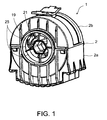
- FIG. 1 shows a coil bearing 1 for blinds with lamellar elements in a perspective view.
- the spiral bearing 1 comprises a multi-part bearing housing 2 with a trough-like housing bottom 2a and a hood 2b, for example, by means of latching spring tongues detachably connected to the housing bottom 2a.
- FIG. 2 shows an exploded view of the coil bearing 1 without caseback 2a and hood 2b.
- a rotary body 28 with a coil 27 for an elevator belt (not shown) and a hollow shaft 19 is rotatably mounted.
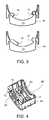
- As bearing serve each two mutually corresponding semicircular recesses 25 ( Fig. 1 . 4 ) on the side walls of the Caseback 2a and the hood 2b.
- the hollow shaft 19 includes a continuous polygonal hole 21 for rotationally pushing on the drive shaft of the store. Due to the recesses 25 on the bearing housing 2, the hollow shaft 19 is freely accessible from the outside.
- a wrap spring 33 with two radially outstanding end legs 34 is mounted on a cylindrical sleeve 36 of the rotary body 28 and frictionally coupled with this rotary body 28.
- a rocker 5 which surrounds the turns of the wrap spring 33 and has a recess 35 through which the end limbs 34 of the wrap spring 33 project, is pivotably mounted on a coil-near section of the sleeve 36 with a slightly larger outside diameter.
- a reversing cord 29 is inserted into a groove 38 and held locally, for example by means of a bead 39 or other fixing means on the rocker 5.
- a stop member 13 with two stop means 15, 17 for the end legs 34 of the wrap spring 33 is designed as a replaceable insert for the bearing housing 2.
- the lower part of the insert is designed as a plug-in area 41 and, with the housing 2 open, may optionally be inserted into a corresponding receiving area 23 (FIG. FIG. 4 ) are inserted guided on the housing bottom 2a.
- the plug-in area 41 and the receiving area 23 are matched to one another such that a pivoting movement of the stop part 13 is prevented.
- Stop member 13 are secured by means of a releasable latching connection in its end position on the housing bottom 2a, for example (not shown).
- Stop member 13 could be formed in the housing bottom 2a an externally accessible recess into which a corresponding stop member 13 is inserted to a stop and held or secured in this end position, for example by means of a latching connection to the housing 2 (not shown).
- the pivoting range of the rocker 5 is predetermined by the two stops 15 and 17.
- the wrap spring 33 When lowering the blind the wrap spring 33 is non-positively connected to the rotary body 28 until the rear end leg 34 in the direction of rotation is present at the front stop 17. Up to this point, the wrap spring 33 is coupled to the rotary body 28 and is rotated during rotation of the elevator shaft. By the stop 17 on the front end leg 34 acting in the direction of rotation torque, the wrap spring 33 is decoupled from the rotary body 28 and thus no longer rotated relative to the housing 2. In an analogous manner, the wrap spring 33 is pivoted while pulling up the curtain with the reverse direction of rotation of the elevator shaft until the end leg 34 which is in this direction of rotation is present at the rear stop 15.
- the wrap 33 is decoupled again from the rotary body 28.
- the two end legs 34 protrude through the recess 35 of the rocker 5 and are used when pivoting the Wrap spring 33 as a driver, wherein in the direction of rotation in each case front end leg 34 is present at the respectively adjacent, the recess 35 delimiting edge of the rocker 5.
- the relative position of the stops 15 and 17 and the included by the two end legs 34 angle ⁇ determine the pivoting range and the maximum pivot angle ⁇ ( FIG. 6 ). This is dimensioned so that the slats of the store worn by the two turns of the reversible cords 29 can be pivoted between the open position and the closed position.
- the maximum pivoting angle ⁇ can be easily adapted for different blinds by selected from several stop members 13 with differently arranged stop means 15, 17 each fitting and installed in the bearing housing 2.
- a two-part bearing housing 2 with a housing bottom 2a and a hood 2b (FIG. FIGS. 1 . 4 )
- the respective matching stop member 13 - as well as the other parts of the spiral bearing 1 - used in a simple way in the housing base 2a and then the hood 2b are latchingly connected to the housing bottom 2a.
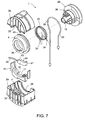
- FIG. 7 shows an exploded view of another turning bearing 1, in which in addition to the stops 15, 17 on the stop member 13, a further stop 43 on a Working position lever 45 is formed.
- This working position lever 45 comprises a cylindrical end portion 47, which is mounted in a corresponding bearing point (not shown) in the housing bottom 2a between the receiving area 23 and the adjacent side wall 4 of the housing base 2a transversely to the pivoting plane of the closer end leg 34 of the wrap spring 33 pivotally.
- the working position lever 45 is pressed in the direction of the wrap spring 33, that the further stop 43 temporarily prevents the adjacent end leg 34 when lowering the blind, up to the stop 17, the closing position of the Slats determines to move on.
- This working position lever 45 can be temporarily pushed back against the force of the spring tongue 49 by (not shown) triggering means shortly before reaching the lowest Absenklage the curtain. As a result, the stop 43 releases the path of movement for the end leg 34 of the wrap spring 33, so that it can continue to turn until it reaches the stop 17.
- the working position lever 45 can be inserted analogously to the stop member 13 and the other parts of the turning bearing 1 in a simple manner from above into the housing bottom 2a.
- components such as the working position lever 45 or the stopper 13 in made of different designs and combined with each other in different variants.
- working position levers may be used in which the position of the stop 43 is different.
- the housing bottom 2a can be easily removed if necessary. In this way, e.g. the stop member 13 are easily replaced.
- one or both stop means 15, 17 may be adjustably formed on the stop member 13, e.g. several detent positions for different maximum tilt angle ⁇ can be provided (not shown). Certain parts, such as the working position lever 45 can optionally be added later in the housing 2.
- the stop member 13 is provided with a label or a code which is uniquely associated with the respectively associated maximum pivot angle ⁇ .
- a color code or a preferably machine-readable other code may be printed on the narrow side of the plug-in area 41 formed on the stop part 13.
- a breakthrough 37 or window formed is formed, through which the code or the marking of the respective inserted stop member 13 is visible.
- the respective setting can be made visible from the outside in an analogous manner.
- FIG. 5 shows a cross section through the coil bearing 1 in the engaged state.
- the wrap spring 33 is non-positively connected to the rotary member 28.
- FIG. 6 shows a cross section of the spiral bearing 1 in the disengaged state, wherein the one end leg 34 of the wrap spring 33 is pressed against the stop 17 during rotation of the elevator shaft.
Landscapes
- Engineering & Computer Science (AREA)
- Structural Engineering (AREA)
- Architecture (AREA)
- Civil Engineering (AREA)
- Blinds (AREA)
- Sliding-Contact Bearings (AREA)
Applications Claiming Priority (1)
| Application Number | Priority Date | Filing Date | Title |
|---|---|---|---|
| CH00289/09A CH700450A1 (de) | 2009-02-27 | 2009-02-27 | Wendelager für Storen mit Lamellenelementen. |
Publications (3)
| Publication Number | Publication Date |
|---|---|
| EP2224091A2 true EP2224091A2 (fr) | 2010-09-01 |
| EP2224091A3 EP2224091A3 (fr) | 2015-01-07 |
| EP2224091B1 EP2224091B1 (fr) | 2020-04-08 |
Family
ID=42299150
Family Applications (1)
| Application Number | Title | Priority Date | Filing Date |
|---|---|---|---|
| EP10405037.2A Active EP2224091B1 (fr) | 2009-02-27 | 2010-02-26 | Culbuteur pour stores à éléments lamellaires |
Country Status (3)
| Country | Link |
|---|---|
| EP (1) | EP2224091B1 (fr) |
| CH (1) | CH700450A1 (fr) |
| ES (1) | ES2801899T3 (fr) |
Cited By (2)
| Publication number | Priority date | Publication date | Assignee | Title |
|---|---|---|---|---|
| EP3263824A1 (fr) * | 2016-06-29 | 2018-01-03 | Storenmaterial Ag | Store à lamelles |
| IT201900002755A1 (it) | 2019-02-26 | 2020-08-26 | Lupak Metal S R L | Apparato frangisole |
Family Cites Families (5)
| Publication number | Priority date | Publication date | Assignee | Title |
|---|---|---|---|---|
| NL148375C (nl) * | 1966-07-15 | 1976-06-15 | Hunter Douglas | Lamellenjaloezie. |
| CH679689A5 (fr) * | 1987-07-16 | 1992-03-31 | Baumann Rolladen | |
| EP0356590B1 (fr) * | 1988-09-01 | 1992-05-27 | Hunter Douglas Industries B.V. | Mécanisme de levage et d'inclinaison pour store vénitien |
| EP1435426B1 (fr) * | 2002-12-30 | 2010-06-16 | Ober S.r.l. | Dispositif de renversement pour un store à lamelles |
| US9598897B2 (en) * | 2007-06-21 | 2017-03-21 | Tait Towers Manufacturing, LLC | Portable curtain retraction device and system |
-
2009
- 2009-02-27 CH CH00289/09A patent/CH700450A1/de not_active Application Discontinuation
-
2010
- 2010-02-26 ES ES10405037T patent/ES2801899T3/es active Active
- 2010-02-26 EP EP10405037.2A patent/EP2224091B1/fr active Active
Non-Patent Citations (1)
| Title |
|---|
| None |
Cited By (3)
| Publication number | Priority date | Publication date | Assignee | Title |
|---|---|---|---|---|
| EP3263824A1 (fr) * | 2016-06-29 | 2018-01-03 | Storenmaterial Ag | Store à lamelles |
| IT201900002755A1 (it) | 2019-02-26 | 2020-08-26 | Lupak Metal S R L | Apparato frangisole |
| EP3702574A1 (fr) | 2019-02-26 | 2020-09-02 | Lupak Metal S.r.l. | Dispositif de pare-soleil |
Also Published As
| Publication number | Publication date |
|---|---|
| CH700450A1 (de) | 2010-08-31 |
| EP2224091A3 (fr) | 2015-01-07 |
| ES2801899T3 (es) | 2021-01-14 |
| EP2224091B1 (fr) | 2020-04-08 |
Similar Documents
| Publication | Publication Date | Title |
|---|---|---|
| DE69912224T2 (de) | Kombinierte Endkappe und Halterung | |
| DE102014200544B4 (de) | Einrichtung zum Steuern eines Luftstroms aus einem Luftausströmer | |
| EP2211012A2 (fr) | Dispositif d'entraînement et de déplacement pour les lamelles d'un store | |
| EP2475537B1 (fr) | Aérateur arqué | |
| EP2546438B1 (fr) | Dispositif prévu pour montage mobile dans une partie de ferrure prévue avec une gorge de ferrure dotée d'une contre-dépouille | |
| DE4336905C1 (de) | Jalousie zur Regulierung eines Gasstroms | |
| DE112014004535T5 (de) | Schiene für eine architektonische Abdeckung | |
| EP0763641B1 (fr) | Dispositif d'actionnement | |
| EP2224091A2 (fr) | Culbuteur pour stores à éléments lamellaires | |
| EP1223299A2 (fr) | Store enroulable, en particulier moustiquaire | |
| CH650311A5 (de) | Rafflamellenstore. | |
| DE3731374C2 (fr) | ||
| EP1839540A2 (fr) | Engrenage destiné au levage et à l'abaissement d'un rideau | |
| DE19949156B4 (de) | Vorrichtung zum Auf- und Abbewegen eines Fahrzeugfensters | |
| EP1659250B1 (fr) | Fenêtre, porte ou analogue avec un renvoi de coin | |
| EP0949402B1 (fr) | Dispositif de sécurité pour une tringle pour manoeuvrer des volets roulants et des stores | |
| DE3713432C2 (fr) | ||
| EP1216861B1 (fr) | Dispositif de guidage d'écoulements d'air dans les installations de chauffage ou de climatisation de véhicule | |
| EP1267031A1 (fr) | Dispositif anti-relevage de sécurité de voulet roulant | |
| DE69410796T2 (de) | Fenster nach jalousie-art | |
| DE20114844U1 (de) | Luftdüse für den Auslass eines Luftstromes aus einem Luftzuführschacht | |
| DE102008018335A1 (de) | Luftauslass | |
| DE202004013244U1 (de) | Schrankmöbel mit Rollladen | |
| EP2250954B1 (fr) | Dispositif de séparation de douche | |
| DE212011100139U1 (de) | Jalousieaufbau |
Legal Events
| Date | Code | Title | Description |
|---|---|---|---|
| PUAI | Public reference made under article 153(3) epc to a published international application that has entered the european phase |
Free format text: ORIGINAL CODE: 0009012 |
|
| AK | Designated contracting states |
Kind code of ref document: A2 Designated state(s): AT BE BG CH CY CZ DE DK EE ES FI FR GB GR HR HU IE IS IT LI LT LU LV MC MK MT NL NO PL PT RO SE SI SK SM TR |
|
| AX | Request for extension of the european patent |
Extension state: AL BA RS |
|
| PUAL | Search report despatched |
Free format text: ORIGINAL CODE: 0009013 |
|
| AK | Designated contracting states |
Kind code of ref document: A3 Designated state(s): AT BE BG CH CY CZ DE DK EE ES FI FR GB GR HR HU IE IS IT LI LT LU LV MC MK MT NL NO PL PT RO SE SI SK SM TR |
|
| AX | Request for extension of the european patent |
Extension state: AL BA RS |
|
| RIC1 | Information provided on ipc code assigned before grant |
Ipc: E06B 9/308 20060101ALI20141128BHEP Ipc: E06B 9/322 20060101ALI20141128BHEP Ipc: E06B 9/307 20060101AFI20141128BHEP |
|
| 17P | Request for examination filed |
Effective date: 20150706 |
|
| RBV | Designated contracting states (corrected) |
Designated state(s): AT BE BG CH CY CZ DE DK EE ES FI FR GB GR HR HU IE IS IT LI LT LU LV MC MK MT NL NO PL PT RO SE SI SK SM TR |
|
| STAA | Information on the status of an ep patent application or granted ep patent |
Free format text: STATUS: EXAMINATION IS IN PROGRESS |
|
| 17Q | First examination report despatched |
Effective date: 20171017 |
|
| GRAP | Despatch of communication of intention to grant a patent |
Free format text: ORIGINAL CODE: EPIDOSNIGR1 |
|
| STAA | Information on the status of an ep patent application or granted ep patent |
Free format text: STATUS: GRANT OF PATENT IS INTENDED |
|
| INTG | Intention to grant announced |
Effective date: 20200109 |
|
| GRAS | Grant fee paid |
Free format text: ORIGINAL CODE: EPIDOSNIGR3 |
|
| GRAA | (expected) grant |
Free format text: ORIGINAL CODE: 0009210 |
|
| STAA | Information on the status of an ep patent application or granted ep patent |
Free format text: STATUS: THE PATENT HAS BEEN GRANTED |
|
| AK | Designated contracting states |
Kind code of ref document: B1 Designated state(s): AT BE BG CH CY CZ DE DK EE ES FI FR GB GR HR HU IE IS IT LI LT LU LV MC MK MT NL NO PL PT RO SE SI SK SM TR |
|
| REG | Reference to a national code |
Ref country code: GB Ref legal event code: FG4D Free format text: NOT ENGLISH |
|
| REG | Reference to a national code |
Ref country code: AT Ref legal event code: REF Ref document number: 1254614 Country of ref document: AT Kind code of ref document: T Effective date: 20200415 Ref country code: CH Ref legal event code: NV Representative=s name: GACHNANG AG PATENTANWAELTE, CH Ref country code: CH Ref legal event code: EP |
|
| REG | Reference to a national code |
Ref country code: DE Ref legal event code: R096 Ref document number: 502010016566 Country of ref document: DE |
|
| REG | Reference to a national code |
Ref country code: IE Ref legal event code: FG4D Free format text: LANGUAGE OF EP DOCUMENT: GERMAN |
|
| REG | Reference to a national code |
Ref country code: NL Ref legal event code: MP Effective date: 20200408 |
|
| REG | Reference to a national code |
Ref country code: LT Ref legal event code: MG4D |
|
| PG25 | Lapsed in a contracting state [announced via postgrant information from national office to epo] |
Ref country code: NL Free format text: LAPSE BECAUSE OF FAILURE TO SUBMIT A TRANSLATION OF THE DESCRIPTION OR TO PAY THE FEE WITHIN THE PRESCRIBED TIME-LIMIT Effective date: 20200408 Ref country code: LT Free format text: LAPSE BECAUSE OF FAILURE TO SUBMIT A TRANSLATION OF THE DESCRIPTION OR TO PAY THE FEE WITHIN THE PRESCRIBED TIME-LIMIT Effective date: 20200408 Ref country code: IS Free format text: LAPSE BECAUSE OF FAILURE TO SUBMIT A TRANSLATION OF THE DESCRIPTION OR TO PAY THE FEE WITHIN THE PRESCRIBED TIME-LIMIT Effective date: 20200808 Ref country code: SE Free format text: LAPSE BECAUSE OF FAILURE TO SUBMIT A TRANSLATION OF THE DESCRIPTION OR TO PAY THE FEE WITHIN THE PRESCRIBED TIME-LIMIT Effective date: 20200408 Ref country code: PT Free format text: LAPSE BECAUSE OF FAILURE TO SUBMIT A TRANSLATION OF THE DESCRIPTION OR TO PAY THE FEE WITHIN THE PRESCRIBED TIME-LIMIT Effective date: 20200817 Ref country code: GR Free format text: LAPSE BECAUSE OF FAILURE TO SUBMIT A TRANSLATION OF THE DESCRIPTION OR TO PAY THE FEE WITHIN THE PRESCRIBED TIME-LIMIT Effective date: 20200709 Ref country code: NO Free format text: LAPSE BECAUSE OF FAILURE TO SUBMIT A TRANSLATION OF THE DESCRIPTION OR TO PAY THE FEE WITHIN THE PRESCRIBED TIME-LIMIT Effective date: 20200708 Ref country code: FI Free format text: LAPSE BECAUSE OF FAILURE TO SUBMIT A TRANSLATION OF THE DESCRIPTION OR TO PAY THE FEE WITHIN THE PRESCRIBED TIME-LIMIT Effective date: 20200408 |
|
| PG25 | Lapsed in a contracting state [announced via postgrant information from national office to epo] |
Ref country code: LV Free format text: LAPSE BECAUSE OF FAILURE TO SUBMIT A TRANSLATION OF THE DESCRIPTION OR TO PAY THE FEE WITHIN THE PRESCRIBED TIME-LIMIT Effective date: 20200408 Ref country code: HR Free format text: LAPSE BECAUSE OF FAILURE TO SUBMIT A TRANSLATION OF THE DESCRIPTION OR TO PAY THE FEE WITHIN THE PRESCRIBED TIME-LIMIT Effective date: 20200408 Ref country code: BG Free format text: LAPSE BECAUSE OF FAILURE TO SUBMIT A TRANSLATION OF THE DESCRIPTION OR TO PAY THE FEE WITHIN THE PRESCRIBED TIME-LIMIT Effective date: 20200708 |
|
| REG | Reference to a national code |
Ref country code: DE Ref legal event code: R097 Ref document number: 502010016566 Country of ref document: DE |
|
| REG | Reference to a national code |
Ref country code: ES Ref legal event code: FG2A Ref document number: 2801899 Country of ref document: ES Kind code of ref document: T3 Effective date: 20210114 |
|
| PG25 | Lapsed in a contracting state [announced via postgrant information from national office to epo] |
Ref country code: CZ Free format text: LAPSE BECAUSE OF FAILURE TO SUBMIT A TRANSLATION OF THE DESCRIPTION OR TO PAY THE FEE WITHIN THE PRESCRIBED TIME-LIMIT Effective date: 20200408 Ref country code: RO Free format text: LAPSE BECAUSE OF FAILURE TO SUBMIT A TRANSLATION OF THE DESCRIPTION OR TO PAY THE FEE WITHIN THE PRESCRIBED TIME-LIMIT Effective date: 20200408 Ref country code: SM Free format text: LAPSE BECAUSE OF FAILURE TO SUBMIT A TRANSLATION OF THE DESCRIPTION OR TO PAY THE FEE WITHIN THE PRESCRIBED TIME-LIMIT Effective date: 20200408 Ref country code: EE Free format text: LAPSE BECAUSE OF FAILURE TO SUBMIT A TRANSLATION OF THE DESCRIPTION OR TO PAY THE FEE WITHIN THE PRESCRIBED TIME-LIMIT Effective date: 20200408 Ref country code: DK Free format text: LAPSE BECAUSE OF FAILURE TO SUBMIT A TRANSLATION OF THE DESCRIPTION OR TO PAY THE FEE WITHIN THE PRESCRIBED TIME-LIMIT Effective date: 20200408 |
|
| PLBE | No opposition filed within time limit |
Free format text: ORIGINAL CODE: 0009261 |
|
| STAA | Information on the status of an ep patent application or granted ep patent |
Free format text: STATUS: NO OPPOSITION FILED WITHIN TIME LIMIT |
|
| PG25 | Lapsed in a contracting state [announced via postgrant information from national office to epo] |
Ref country code: SK Free format text: LAPSE BECAUSE OF FAILURE TO SUBMIT A TRANSLATION OF THE DESCRIPTION OR TO PAY THE FEE WITHIN THE PRESCRIBED TIME-LIMIT Effective date: 20200408 Ref country code: PL Free format text: LAPSE BECAUSE OF FAILURE TO SUBMIT A TRANSLATION OF THE DESCRIPTION OR TO PAY THE FEE WITHIN THE PRESCRIBED TIME-LIMIT Effective date: 20200408 |
|
| 26N | No opposition filed |
Effective date: 20210112 |
|
| PG25 | Lapsed in a contracting state [announced via postgrant information from national office to epo] |
Ref country code: SI Free format text: LAPSE BECAUSE OF FAILURE TO SUBMIT A TRANSLATION OF THE DESCRIPTION OR TO PAY THE FEE WITHIN THE PRESCRIBED TIME-LIMIT Effective date: 20200408 |
|
| PG25 | Lapsed in a contracting state [announced via postgrant information from national office to epo] |
Ref country code: MC Free format text: LAPSE BECAUSE OF FAILURE TO SUBMIT A TRANSLATION OF THE DESCRIPTION OR TO PAY THE FEE WITHIN THE PRESCRIBED TIME-LIMIT Effective date: 20200408 |
|
| GBPC | Gb: european patent ceased through non-payment of renewal fee |
Effective date: 20210226 |
|
| REG | Reference to a national code |
Ref country code: BE Ref legal event code: MM Effective date: 20210228 |
|
| PG25 | Lapsed in a contracting state [announced via postgrant information from national office to epo] |
Ref country code: LU Free format text: LAPSE BECAUSE OF NON-PAYMENT OF DUE FEES Effective date: 20210226 |
|
| PG25 | Lapsed in a contracting state [announced via postgrant information from national office to epo] |
Ref country code: IE Free format text: LAPSE BECAUSE OF NON-PAYMENT OF DUE FEES Effective date: 20210226 Ref country code: GB Free format text: LAPSE BECAUSE OF NON-PAYMENT OF DUE FEES Effective date: 20210226 |
|
| PG25 | Lapsed in a contracting state [announced via postgrant information from national office to epo] |
Ref country code: BE Free format text: LAPSE BECAUSE OF NON-PAYMENT OF DUE FEES Effective date: 20210228 |
|
| PG25 | Lapsed in a contracting state [announced via postgrant information from national office to epo] |
Ref country code: HU Free format text: LAPSE BECAUSE OF FAILURE TO SUBMIT A TRANSLATION OF THE DESCRIPTION OR TO PAY THE FEE WITHIN THE PRESCRIBED TIME-LIMIT; INVALID AB INITIO Effective date: 20100226 Ref country code: CY Free format text: LAPSE BECAUSE OF FAILURE TO SUBMIT A TRANSLATION OF THE DESCRIPTION OR TO PAY THE FEE WITHIN THE PRESCRIBED TIME-LIMIT Effective date: 20200408 |
|
| P01 | Opt-out of the competence of the unified patent court (upc) registered |
Effective date: 20230526 |
|
| PG25 | Lapsed in a contracting state [announced via postgrant information from national office to epo] |
Ref country code: MK Free format text: LAPSE BECAUSE OF FAILURE TO SUBMIT A TRANSLATION OF THE DESCRIPTION OR TO PAY THE FEE WITHIN THE PRESCRIBED TIME-LIMIT Effective date: 20200408 |
|
| REG | Reference to a national code |
Ref country code: CH Ref legal event code: PK Free format text: BERICHTIGUNGEN |
|
| PG25 | Lapsed in a contracting state [announced via postgrant information from national office to epo] |
Ref country code: TR Free format text: LAPSE BECAUSE OF FAILURE TO SUBMIT A TRANSLATION OF THE DESCRIPTION OR TO PAY THE FEE WITHIN THE PRESCRIBED TIME-LIMIT Effective date: 20200408 |
|
| PG25 | Lapsed in a contracting state [announced via postgrant information from national office to epo] |
Ref country code: MT Free format text: LAPSE BECAUSE OF FAILURE TO SUBMIT A TRANSLATION OF THE DESCRIPTION OR TO PAY THE FEE WITHIN THE PRESCRIBED TIME-LIMIT Effective date: 20200408 |
|
| REG | Reference to a national code |
Ref country code: CH Ref legal event code: U11 Free format text: ST27 STATUS EVENT CODE: U-0-0-U10-U11 (AS PROVIDED BY THE NATIONAL OFFICE) Effective date: 20260301 |
|
| PGFP | Annual fee paid to national office [announced via postgrant information from national office to epo] |
Ref country code: ES Payment date: 20260319 Year of fee payment: 17 |
|
| PGFP | Annual fee paid to national office [announced via postgrant information from national office to epo] |
Ref country code: DE Payment date: 20260217 Year of fee payment: 17 |
|
| PGFP | Annual fee paid to national office [announced via postgrant information from national office to epo] |
Ref country code: AT Payment date: 20260216 Year of fee payment: 17 |
|
| PGFP | Annual fee paid to national office [announced via postgrant information from national office to epo] |
Ref country code: IT Payment date: 20260227 Year of fee payment: 17 |
|
| PGFP | Annual fee paid to national office [announced via postgrant information from national office to epo] |
Ref country code: FR Payment date: 20260219 Year of fee payment: 17 |
|
| PGFP | Annual fee paid to national office [announced via postgrant information from national office to epo] |
Ref country code: CH Payment date: 20260301 Year of fee payment: 17 |