EP2229204B1 - Dispositif de pulvérisation de fluides - Google Patents
Dispositif de pulvérisation de fluides Download PDFInfo
- Publication number
- EP2229204B1 EP2229204B1 EP08869999A EP08869999A EP2229204B1 EP 2229204 B1 EP2229204 B1 EP 2229204B1 EP 08869999 A EP08869999 A EP 08869999A EP 08869999 A EP08869999 A EP 08869999A EP 2229204 B1 EP2229204 B1 EP 2229204B1
- Authority
- EP
- European Patent Office
- Prior art keywords
- aerosol
- cartridge
- fluid
- treatment
- mist
- Prior art date
- Legal status (The legal status is an assumption and is not a legal conclusion. Google has not performed a legal analysis and makes no representation as to the accuracy of the status listed.)
- Not-in-force
Links
- 239000012530 fluid Substances 0.000 title claims description 47
- 238000011282 treatment Methods 0.000 claims description 46
- 239000000443 aerosol Substances 0.000 claims description 42
- 239000003595 mist Substances 0.000 claims description 23
- 239000002245 particle Substances 0.000 claims description 16
- 241001465754 Metazoa Species 0.000 claims description 10
- 239000007788 liquid Substances 0.000 description 15
- 239000003921 oil Substances 0.000 description 14
- 235000019198 oils Nutrition 0.000 description 14
- 239000012266 salt solution Substances 0.000 description 11
- FAPWRFPIFSIZLT-UHFFFAOYSA-M Sodium chloride Chemical compound [Na+].[Cl-] FAPWRFPIFSIZLT-UHFFFAOYSA-M 0.000 description 8
- 239000000243 solution Substances 0.000 description 8
- 238000007789 sealing Methods 0.000 description 7
- 239000007864 aqueous solution Substances 0.000 description 6
- 238000000034 method Methods 0.000 description 6
- XLYOFNOQVPJJNP-UHFFFAOYSA-N water Substances O XLYOFNOQVPJJNP-UHFFFAOYSA-N 0.000 description 6
- 239000000654 additive Substances 0.000 description 5
- 239000000839 emulsion Substances 0.000 description 5
- 238000004519 manufacturing process Methods 0.000 description 4
- 239000002184 metal Substances 0.000 description 4
- 239000003814 drug Substances 0.000 description 3
- 230000008569 process Effects 0.000 description 3
- 230000009471 action Effects 0.000 description 2
- 238000009412 basement excavation Methods 0.000 description 2
- 230000005484 gravity Effects 0.000 description 2
- 230000033001 locomotion Effects 0.000 description 2
- 239000000463 material Substances 0.000 description 2
- 239000004006 olive oil Substances 0.000 description 2
- 235000008390 olive oil Nutrition 0.000 description 2
- 239000004033 plastic Substances 0.000 description 2
- 229920003023 plastic Polymers 0.000 description 2
- 239000011780 sodium chloride Substances 0.000 description 2
- 239000000126 substance Substances 0.000 description 2
- 230000000699 topical effect Effects 0.000 description 2
- 239000000341 volatile oil Substances 0.000 description 2
- FIKFLLIUPUVONI-UHFFFAOYSA-N 8-(2-phenylethyl)-1-oxa-3,8-diazaspiro[4.5]decan-2-one;hydrochloride Chemical compound Cl.O1C(=O)NCC11CCN(CCC=2C=CC=CC=2)CC1 FIKFLLIUPUVONI-UHFFFAOYSA-N 0.000 description 1
- 239000004696 Poly ether ether ketone Substances 0.000 description 1
- 238000005299 abrasion Methods 0.000 description 1
- 238000010521 absorption reaction Methods 0.000 description 1
- 239000002253 acid Substances 0.000 description 1
- 239000004480 active ingredient Substances 0.000 description 1
- 239000013543 active substance Substances 0.000 description 1
- 239000007900 aqueous suspension Substances 0.000 description 1
- 238000003287 bathing Methods 0.000 description 1
- 230000009286 beneficial effect Effects 0.000 description 1
- 230000008901 benefit Effects 0.000 description 1
- JUPQTSLXMOCDHR-UHFFFAOYSA-N benzene-1,4-diol;bis(4-fluorophenyl)methanone Chemical compound OC1=CC=C(O)C=C1.C1=CC(F)=CC=C1C(=O)C1=CC=C(F)C=C1 JUPQTSLXMOCDHR-UHFFFAOYSA-N 0.000 description 1
- 239000000919 ceramic Substances 0.000 description 1
- 229910010293 ceramic material Inorganic materials 0.000 description 1
- 230000006835 compression Effects 0.000 description 1
- 238000007906 compression Methods 0.000 description 1
- 238000010276 construction Methods 0.000 description 1
- 238000001816 cooling Methods 0.000 description 1
- 238000005260 corrosion Methods 0.000 description 1
- 230000007797 corrosion Effects 0.000 description 1
- 230000001419 dependent effect Effects 0.000 description 1
- 238000011161 development Methods 0.000 description 1
- 230000018109 developmental process Effects 0.000 description 1
- 238000009826 distribution Methods 0.000 description 1
- 229940079593 drug Drugs 0.000 description 1
- 238000001704 evaporation Methods 0.000 description 1
- 230000008020 evaporation Effects 0.000 description 1
- 239000011521 glass Substances 0.000 description 1
- 230000035876 healing Effects 0.000 description 1
- 238000002347 injection Methods 0.000 description 1
- 239000007924 injection Substances 0.000 description 1
- 239000002991 molded plastic Substances 0.000 description 1
- 239000006199 nebulizer Substances 0.000 description 1
- 239000007764 o/w emulsion Substances 0.000 description 1
- 229920003229 poly(methyl methacrylate) Polymers 0.000 description 1
- 229920002530 polyetherether ketone Polymers 0.000 description 1
- 239000004926 polymethyl methacrylate Substances 0.000 description 1
- 230000002685 pulmonary effect Effects 0.000 description 1
- 210000002345 respiratory system Anatomy 0.000 description 1
- 208000023504 respiratory system disease Diseases 0.000 description 1
- 208000017520 skin disease Diseases 0.000 description 1
- 238000005507 spraying Methods 0.000 description 1
- 238000004544 sputter deposition Methods 0.000 description 1
- 229910001220 stainless steel Inorganic materials 0.000 description 1
- 239000010935 stainless steel Substances 0.000 description 1
- 230000004936 stimulating effect Effects 0.000 description 1
- 239000000725 suspension Substances 0.000 description 1
- 239000008399 tap water Substances 0.000 description 1
- 235000020679 tap water Nutrition 0.000 description 1
- 230000001225 therapeutic effect Effects 0.000 description 1
- 238000002207 thermal evaporation Methods 0.000 description 1
- 230000007704 transition Effects 0.000 description 1
- 238000009423 ventilation Methods 0.000 description 1
- 239000011782 vitamin Substances 0.000 description 1
- 229940088594 vitamin Drugs 0.000 description 1
- 229930003231 vitamin Natural products 0.000 description 1
- 235000013343 vitamin Nutrition 0.000 description 1
- 235000019195 vitamin supplement Nutrition 0.000 description 1
- 239000007762 w/o emulsion Substances 0.000 description 1
Images


Classifications
-
- A—HUMAN NECESSITIES
- A61—MEDICAL OR VETERINARY SCIENCE; HYGIENE
- A61M—DEVICES FOR INTRODUCING MEDIA INTO, OR ONTO, THE BODY; DEVICES FOR TRANSDUCING BODY MEDIA OR FOR TAKING MEDIA FROM THE BODY; DEVICES FOR PRODUCING OR ENDING SLEEP OR STUPOR
- A61M11/00—Sprayers or atomisers specially adapted for therapeutic purposes
-
- A—HUMAN NECESSITIES
- A61—MEDICAL OR VETERINARY SCIENCE; HYGIENE
- A61M—DEVICES FOR INTRODUCING MEDIA INTO, OR ONTO, THE BODY; DEVICES FOR TRANSDUCING BODY MEDIA OR FOR TAKING MEDIA FROM THE BODY; DEVICES FOR PRODUCING OR ENDING SLEEP OR STUPOR
- A61M11/00—Sprayers or atomisers specially adapted for therapeutic purposes
- A61M11/006—Sprayers or atomisers specially adapted for therapeutic purposes operated by applying mechanical pressure to the liquid to be sprayed or atomised
- A61M11/007—Syringe-type or piston-type sprayers or atomisers
-
- B—PERFORMING OPERATIONS; TRANSPORTING
- B05—SPRAYING OR ATOMISING IN GENERAL; APPLYING FLUENT MATERIALS TO SURFACES, IN GENERAL
- B05B—SPRAYING APPARATUS; ATOMISING APPARATUS; NOZZLES
- B05B7/00—Spraying apparatus for discharge of liquids or other fluent materials from two or more sources, e.g. of liquid and air, of powder and gas
- B05B7/02—Spray pistols; Apparatus for discharge
- B05B7/08—Spray pistols; Apparatus for discharge with separate outlet orifices, e.g. to form parallel jets, i.e. the axis of the jets being parallel, to form intersecting jets, i.e. the axis of the jets converging but not necessarily intersecting at a point
-
- B—PERFORMING OPERATIONS; TRANSPORTING
- B05—SPRAYING OR ATOMISING IN GENERAL; APPLYING FLUENT MATERIALS TO SURFACES, IN GENERAL
- B05B—SPRAYING APPARATUS; ATOMISING APPARATUS; NOZZLES
- B05B9/00—Spraying apparatus for discharge of liquids or other fluent material, without essentially mixing with gas or vapour
- B05B9/03—Spraying apparatus for discharge of liquids or other fluent material, without essentially mixing with gas or vapour characterised by means for supplying liquid or other fluent material
- B05B9/04—Spraying apparatus for discharge of liquids or other fluent material, without essentially mixing with gas or vapour characterised by means for supplying liquid or other fluent material with pressurised or compressible container; with pump
- B05B9/0403—Spraying apparatus for discharge of liquids or other fluent material, without essentially mixing with gas or vapour characterised by means for supplying liquid or other fluent material with pressurised or compressible container; with pump with pumps for liquids or other fluent material
- B05B9/0413—Spraying apparatus for discharge of liquids or other fluent material, without essentially mixing with gas or vapour characterised by means for supplying liquid or other fluent material with pressurised or compressible container; with pump with pumps for liquids or other fluent material with reciprocating pumps, e.g. membrane pump, piston pump, bellow pump
-
- A—HUMAN NECESSITIES
- A61—MEDICAL OR VETERINARY SCIENCE; HYGIENE
- A61H—PHYSICAL THERAPY APPARATUS, e.g. DEVICES FOR LOCATING OR STIMULATING REFLEX POINTS IN THE BODY; ARTIFICIAL RESPIRATION; MASSAGE; BATHING DEVICES FOR SPECIAL THERAPEUTIC OR HYGIENIC PURPOSES OR SPECIFIC PARTS OF THE BODY
- A61H33/00—Bathing devices for special therapeutic or hygienic purposes
- A61H33/04—Appliances for sand, mud, wax or foam baths; Appliances for metal baths, e.g. using metal salt solutions
- A61H2033/048—Baths using solutions, e.g. salts
-
- A—HUMAN NECESSITIES
- A61—MEDICAL OR VETERINARY SCIENCE; HYGIENE
- A61H—PHYSICAL THERAPY APPARATUS, e.g. DEVICES FOR LOCATING OR STIMULATING REFLEX POINTS IN THE BODY; ARTIFICIAL RESPIRATION; MASSAGE; BATHING DEVICES FOR SPECIAL THERAPEUTIC OR HYGIENIC PURPOSES OR SPECIFIC PARTS OF THE BODY
- A61H33/00—Bathing devices for special therapeutic or hygienic purposes
- A61H33/06—Artificial hot-air or cold-air baths; Steam or gas baths or douches, e.g. sauna or Finnish baths
-
- A—HUMAN NECESSITIES
- A61—MEDICAL OR VETERINARY SCIENCE; HYGIENE
- A61M—DEVICES FOR INTRODUCING MEDIA INTO, OR ONTO, THE BODY; DEVICES FOR TRANSDUCING BODY MEDIA OR FOR TAKING MEDIA FROM THE BODY; DEVICES FOR PRODUCING OR ENDING SLEEP OR STUPOR
- A61M2202/00—Special media to be introduced, removed or treated
- A61M2202/04—Liquids
- A61M2202/0468—Liquids non-physiological
-
- B—PERFORMING OPERATIONS; TRANSPORTING
- B05—SPRAYING OR ATOMISING IN GENERAL; APPLYING FLUENT MATERIALS TO SURFACES, IN GENERAL
- B05B—SPRAYING APPARATUS; ATOMISING APPARATUS; NOZZLES
- B05B7/00—Spraying apparatus for discharge of liquids or other fluent materials from two or more sources, e.g. of liquid and air, of powder and gas
- B05B7/0075—Nozzle arrangements in gas streams
Definitions
- the present invention relates to a device for atomizing fluids, in particular a device for producing a therapeutically effective aerosol in a treatment room, for example, in particular for the treatment of humans or animals with aerosols, which are produced by atomizing aqueous and / or oily solutions.
- WO 00/44331 A1 describes a whole-body Nebelbadvorraum and a method for administering a whole-body mist bath, where at temperatures of less than 35 ° C, a mist bath is generated, wherein a liquid is compressed to a pressure of more than 100 bar and then exploded via a nozzle in ejects a treatment cubicle so that the liquid, when ejected into the cabin, is atomized into many small liquid droplets due to its high internal pressure.
- WO 00/44331 A1 It has been proposed to use aqueous saline solutions or oils with vitamin supplements or ethereal additives to produce the mist.
- nebulizers are a hollow cylindrical compression chamber provided with a closable opening which is connected via a line to a high-pressure pump, from which the liquid to be atomized is conveyed.
- a disadvantage of the solution known from this prior art is, on the one hand, that a separate nebulizer with a separate high-pressure pump is required for each fluid to be atomized.
- a high-pressure pump in a humid environment poses a safety risk, especially when aqueous saline solutions are sprayed, which have a much higher conductivity than normal tap water.
- the present invention is therefore based on the technical problem of providing a device for atomising at least two different fluids, in particular for the treatment of humans or animals with aqueous and oily aerosols, which is simple in construction and reliable and safe in a moist environment. in which, for example, aerosols are from aqueous salt solutions, is operable.
- a fluid to be atomized is pressurized and expelled at a flow rate in the range from 50 to 3000 m / s through a nozzle into a treatment space.
- the flow rate refers to the flow rate of the fluid at the nozzle.
- the nozzle preferably has at least one outlet opening with a diameter which is in the range of 0.05 to 0.2 mm, preferably in the range of 0.08 to 0.15 mm and most preferably in the range of 0.1 mm , When flowing through the fine nozzle, the fluid is torn into the smallest particles that form an aerosol in the treatment room.
- the outlet opening of the nozzle may be made of any abrasion resistant and resistant to the fluids to be atomized material, for example of a suitable plastic or ceramic material.
- the nozzle consists of a stainless and acid-resistant stainless steel and may be formed, for example, as a plate with a thickness of 0.5 to 1 mm.
- the nozzle may have one or more outlet openings.
- the outlet openings can be drilled, for example, mechanically or with a laser beam or high-pressure water jet.
- the nozzle as an injection molded part manufacture, wherein the corresponding nozzle openings already left out during the manufacturing process.
- the flow rate of the fluid leaving the nozzle is preferably in the range of 100 to 250 m / s and more preferably about 150 m / s.
- the fluid to be atomized is preferably pressurized to a pressure of up to 1000 bar.
- the ejected particles have a mean diameter that is tuned to the particular area of application of the aerosol.
- the mean particle diameter is 0.05 to 5 microns, more preferably in the range of 0.1 to 0.9 microns, since particles in this order of magnitude have a good pulmonary activity, so that a particularly effective absorption is ensured.
- the particle diameters may also be much larger, since in this case, it merely has to be ensured that the droplets of the atomized fluid reach the skin.
- the fluid to be atomized is an aqueous solution, an aqueous emulsion, in particular an oil-in-water emulsion, an oily solution, an oily emulsion, in particular a water-in-oil emulsion, an aqueous suspension or an oily one Suspension.
- the aqueous solution is particularly preferably a salt solution.
- an oily solution it is preferably a solution comprising essential oils.
- the fluid may comprise at least one therapeutically active ingredient, for example topical application of medicaments for the treatment of skin diseases or inhalation of the aerosol medicaments for the treatment of respiratory diseases.
- any room can be used as the treatment room, which allows the skin or the respiratory tract of the person or the animal to be treated to come into contact with the atomized aerosol particles, in accordance with the respective application.
- the treatment room may also be an inhalation mask.
- the treatment room is a treatment chamber which completely or partially surrounds the animal to be treated with the aerosol.
- a special feature of the process, in particular compared to the typical steam bath is that the treatment can be carried out at relatively low temperatures, since no thermal evaporation of fluids is necessary for aerosol production.
- the preferred temperature in the treatment chamber is at ambient temperature or slightly above ambient temperature. In particularly hot regions of the earth, however, cooling of the treatment chamber to temperatures below the ambient temperature may also be advantageous.
- the treatment chamber is therefore preferably temperature-controlled to a temperature in the range from 0 to 70 ° C., preferably in the range from 20 to 35 ° C.
- the typical treatment time with the aerosol is in the range of minutes, for example in the range of 10 to 30 minutes.
- the aerosol is discharged at an average flow rate in the range of a few milliliters per minute to several hundred milliliters per minute. Most preferably, the average flow rate is in the range of 10 to 100 milliliters per minute.
- the invention relates to a device for atomizing fluids, in particular to a device for producing a therapeutically effective aerosol, with a treatment space which completely or partially surrounds a living being to be treated, and at least one aerosol generator for delivering an aerosol into the treatment space, wherein the aerosol generator so is formed so that a fluid to be atomized can be pressurized and ejected into the treatment space through at least one outlet opening in the form of small particles at a flow rate in the range of 50 to 300 meters per second.
- the fluid to be atomized is arranged in a cartridge which has the at least one outlet opening for atomizing the fluid and a movable piston which can be moved by a drive device.
- the cartridge is advantageously designed exchangeable, so that the device according to the invention can be put back into a ready-for-use state after use by simply replacing the cartridge.
- the cartridge can be designed as a disposable cartridge or as a reusable cartridge.
- the cartridge can be subjected to an internal pressure of several hundred bars.
- the cartridge can be made of any inert, pressure and chemical resistant material, such as plastic, metal, glass or ceramic.
- the cartridge is an injection-molded plastic part, for example made of PEEK.
- the cartridge in a cartridge or the whole Partially enclosing metal support are arranged to ensure the necessary pressure resistance.
- the cartridge will hold a volume of fluid to be atomized that can range from 20 to 40 ml for human applications and from about 100 ml to several hundred ml in large animal applications.
- the cartridge is already prefilled by the manufacturer, so that compliance with hygienic and drug requirements is guaranteed.
- the cartridge contains only one cylinder, so that several cartridges must be used one after the other or simultaneously for the delivery of a plurality of different fluids.
- a cartridge can also be designed as a multi-cylinder cartridge, so that the simultaneous delivery of several different fluids is also made possible by means of a cartridge.
- the drive motor used is preferably a low-voltage motor, particularly preferably a low-voltage linear motor, such as a low-voltage electric cylinder.
- the low-voltage electric cylinder can be operated at an operating voltage of 24 V, for example. This is a safe operation in a humid environment, for example in a mist of aerosol particles, which were generated from an aqueous salt solution possible.
- An electric cylinder as a drive motor also has the advantage that such a motor can be designed completely encapsulated, with only the drive spindle is sealed out by a suitable seal out of the closed housing. There is therefore no risk that aerosol particles of the aqueous salt solution penetrate into the electric cylinder and lead to corrosion or short circuits.
- the first fluid is particularly preferably an aqueous solution, for example water or an aqueous salt solution.
- the second fluid is preferably an oil, preferably an oil containing additives.
- Typical additives may be, for example, ethereal substances, vitamins, pharmaceutically active substances and the like.
- the first fluid may contain appropriate additives.
- the invention also relates to a mist generator for treating a person or an animal with aqueous and oily aerosols, which is characterized in that the mist generator comprises a device for atomising at least two different fluids of the type defined above for producing a water and oil mist.
- the mist generator may be placed in a room, for example in a horse stable, a kennel or a treatment room for persons in which the aerosol mist is to be generated.
- the mist generator may be part of a treatment cabin or may itself comprise a treatment chamber which may surround the whole body or a part of the body of the person to be treated or of the animal to be treated.
- the fluids are preferably subjected to a pressure of at least 100 bar, more preferably a pressure of between 100 and 800 bar, and most preferably a pressure of between 400 and 600 bar, for example a pressure of about 570 bar.
- a pressure of at least 100 bar more preferably a pressure of between 100 and 800 bar, and most preferably a pressure of between 400 and 600 bar, for example a pressure of about 570 bar.
- the sudden release of the thus compressed liquid to ambient pressure produces aerosol particles, which typically have a size of between 0.5 and 10 ⁇ m 3 and more preferably of about 1 ⁇ m 3 .
- the typical amounts of liquid sprayed as part of a treatment depend on the dimensions of the treatment room in which the aerosol mist is to be generated. For partial body treatments of a person liquid quantities of a few milliliters already sufficient. For the treatment of a person in an aerosol cabin such as in WO 00/44331 A1 Typically, about 25 ml of fluid is nebulized, while in the treatment of larger animals, such as horses in appropriate housing, several hundred milliliters of fluid per treatment can be nebulized.
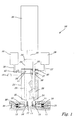
- the non-inventive device for atomizing two different fluids is designated overall by the reference numeral 10.
- the device 10 has a first atomizer head 11 and a second atomizer head 12.
- a first high-pressure chamber 13 is recessed, which has an outlet opening 14 which is closed by a movable mandrel 15.
- the second atomizing head 12 has a second high pressure chamber 16, which has an outlet opening 17 to the environment, which is also closed by a movable mandrel 18.
- the mandrel 15 is biased by a coil spring 19 against the outlet opening 14, while the mandrel 18 is biased by a coil spring 20 against the outlet opening 17.
- the bias voltages of the coil springs 19 and 20 are adjustable via screw 21 and 22 from the outside.
- the diameter of the outlet openings 14,17 in the example shown about 0.5 mm.
- the coil springs 19 and 20 are biased in the example so that when the internal pressure in the high pressure chambers 13 and 16 exceeds 570 bar, the mandrels are pushed away from the seats against the bias of the springs and annular outlet slots at the edge of the outlet openings 14, 17 release, through which the fluids in the high pressure chambers 13 and 16 are explosively released into the environment and atomized into fine droplets due to the drop in pressure to ambient pressure.
- the device To generate the pressure of about 570 bar in the high pressure chambers 13 and 16, the device has a high pressure pump 23, which supplies the first high pressure chamber 13 via a high pressure line 24 with the first fluid and the second high pressure pump 16 via a high pressure line 25 with the second fluid ,
- a first supply line 27 opens, starting from a reservoir 28, in which the first fluid is arranged. Accordingly, in the high-pressure pump 23 in the Operaausriss the FIG. 1 only shown in phantom second cylinder 29 is provided in the one hand, the second high-pressure line 25 and on the other hand, a second supply line 30 opens, which connects the second cylinder 29 with a reservoir 31 for the second fluid.
- first cylinder 26 engages a first piston 32, while in the second cylinder 29, a second piston 33 engages.
- the two pistons 32, 33 are connected by a cross strut 34 is connected to the linearly movable spindle 35 of a low-voltage electric cylinder 36 operated at 24V.
- the low-voltage electric cylinder causes the reciprocating movement of the pistons 32, 33 in the cylinders 26, 29 of the high-pressure pump 23.
- the first supply line 27 opens via a first inlet opening 37 in the lateral end region of the first cylinder 26.
- the second supply line 30 opens via a second inlet opening 38 in the end region of the second cylinder 29.
- the mouth portion of the supply line 27 is in the direction of the atomizer head 11 by means a first sealing ring 39 and sealed to the electric cylinder 36 through a second sealing ring 40.
- the piston 32 is guided in the sealing rings 39 and 40 liquid-tight.
- Corresponding sealing rings are arranged in the region of the second inlet opening 38, but in FIG. 1 not recognizable due to the partial tear-off representation. Between the respective pairs of sealing rings vent openings 41 are also arranged, through which the cylinders 26,29 can communicate with the environment (in FIG. 1 only the vent 41 of the second cylinder 29 is shown, while a corresponding, in the partial excavation of the FIG. 1 not shown vent opening is also provided for the first cylinder 26.
- a controllable inlet valve 42 is arranged, which is programmable via a control unit 43.
- the corresponding liquids can be fed into the reservoirs 28, 31 from prefabricated vials.
- the lines 27, 30 can be inserted into (in FIG. 1 not shown) connecting piece to which pre-assembled liquid container can be connected.
- the device 10 and the liquid reservoirs 28 and 38 are in the example of FIG. 1 arranged so that the saline solution in the reservoir 28 and the oil in the reservoir 31 can flow under the action of gravity in the vertically oriented cylinders 26 and 29, respectively.
- the discharge of the liquids from the reservoir is prevented by the pistons 32 and 33, which block the ventilation openings 37 and 38, respectively.
- the inlet valve 42 is kept closed, so that regardless of the position of the piston 33, no oil can enter the cylinder 29.
- the piston 32 is pulled out of the cylinder 26 so far that the inlet opening 37 is released, aqueous salt solution flows out of the container 28 due to the negative pressure resulting from the withdrawal of the piston 32 in the cylinder 26 and the action of gravity
- air contained in the cylinder 26 can escape via the vent opening (not shown) of the cylinder 26.
- the piston 32 is pulled out at the maximum up to the second sealing ring 40, so that a seal is always ensured to the environment.
- the saline solution flowing into the cylinder 26 then also passes via the high-pressure line 34 into the first high-pressure chamber 13. As long as only ambient pressure is present, the salt solution can not leave the high-pressure chamber 13. As soon as the piston 32 is moved back into the cylinder 26, in the cylinder 26, the high pressure line 24 and the high pressure chamber 13, a pressure which increases until the spout 15 closing the outlet opening 14 against the bias of the coil spring 19 of his Seat lifted and an annular exit slit at the outlet opening 14 is released. In the example shown, the spring 19 is biased so that the outlet opening 14 is released at a pressure of 570 bar. After ejection of the liquid, the pressure drops below the predetermined limit again and the mandrel 15 closes the outlet again tightly.
- the piston 32 is pulled out again up to the second sealing ring 40 and further saline solution can flow from the reservoir 28.
- This process is repeated until it is ensured that the originally contained in the reservoir 28 volume of aqueous salt solution has been atomized.
- the number of lifting operations can be calculated from the volume of the salt solutions originally present and the volume sprayed per piston stroke.
- the controller 43 opens the inlet valve 42, so that oil is withdrawn from the reservoir 31 on the next withdrawal of the piston 33 from the second cylinder 29 into the second cylinder 29, the second high-pressure line 25 and the second high-pressure chamber 16 can flow.
- the described method ensures that, on the one hand, saline solution and, on the other hand, oil can be atomized with one and the same device, but only saline solution and subsequently only oil are dispensed, which ensures an optimal therapeutic effect.
- the aerosol mist generated at the outlet openings 14 and 17 does not have to be dispensed directly into the treatment room, but that, for example, an antechamber may be provided, from which the aerosol mist is delivered via an additional fan into the actual treatment room, as this for example in the WO 00/44331 A1 is shown.
- the silencers also described there may be provided to minimize noise.
- a typical aerosol treatment cabin, in which the sputtering device may be arranged, will be described below in connection with the FIG. 5 described and is also in WO 00/44331 A1 shown in more detail.
- FIG. 2 is a variant of the device FIG. 1 in a partial view, wherein components which have the same or a corresponding function as components of the device FIG. 1 meet, are designated by the same reference numerals.
- the variant of FIG. 2 differs from FIG. 1 only in the design of the atomizer heads 11, 12, which are particularly simple in the present case, since the high pressure lines 24, 25 via a connecting piece 44, 45 directly into the nozzle 46, 47 open, where in each case a metal plate 48, 49 with the nozzle openings 14, 17 is arranged.
- the metal plate is secured by a union nut 50, 51 respectively.
- the reference numerals 52, 53 are in FIG. 2 the ejected from the nozzles 14, 17 aerosol particles shown.
- filters 54, 55 are arranged, which filter out larger particles from the fluids to be atomized, so that clogging or even damage to the nozzles is prevented.
- FIG. 3 shows a variant of the device according to the invention for atomizing fluids, which is designated overall by the reference numeral 60.
- the fluid to be atomized is located in a cartridge 61 which has an outlet nozzle 62 and a movable plunger 63 arranged at the opposite end of the cartridge.
- the cartridge 61 is interchangeably arranged in a holder 64, in which it is positioned so that the end-side punch 63 of the cartridge can be acted upon by a shaft 65 of a hydraulic cylinder 66.
- the shaft 65 is connected to a movable piston 67, which can be reciprocated in the hydraulic cylinder 66.
- the piston 67 divides the hydraulic cylinder into two chambers 68, 69, which can be acted upon via hydraulic lines 70, 71 by means of a hydraulic drive 72 with a hydraulic fluid to reciprocate the piston 67 in a conventional manner.
- the reference numerals 73, 74 and 75 are in FIG. 3 further replacement cartridges referred to, which can be used after use of the cartridge 61 in the holder 64. With 76 is in FIG. 3 the symbolized by the outlet opening 62 of the cartridge 61 atomized fluid.
- FIG. 4 shows a variant of the device of FIG. 3 , which only by the drive of the shaft 65 of the in FIG. 3 different embodiment described.
- Components which have the same or similar functions as components of the embodiment of FIG. 3 are denoted by the same reference numerals and will not be described again.
- the piston skirt 65 of the variant of FIG. 4 purely mechanically operated.
- the drive device has a linear motor 76 which can reciprocate a shaft 77 rectilinearly between an initial position 78 and an end position 79.
- a cross member 80 is articulated, whose opposite end is hinged to the end of the shaft 65.
- the cross member 80 is rotatably fixed at a fulcrum 81, so that two lever arms 82, 83 are formed whose ratio determines the force transmitted from the shaft 77 to the shaft 65.
- FIG. 5 finally shows a treatment chamber 90, in which one or more of the inventive devices for atomizing a therapeutically effective aerosol can be incorporated.
- a treatment chamber 90 in which one or more of the inventive devices for atomizing a therapeutically effective aerosol can be incorporated.
- illustrated treatment chamber 90 is more detailed in the international patent application WO 00/44331 A1 described.
- the treatment chamber 90 is bounded by a bottom plate 91, a ceiling plate 92, side windows 93 made of acrylic glass and two along the arrows A, B movable front discs 94, 95, which allow access to the treatment chamber 90.
- a tube 96 In the treatment chamber 90 extends between the bottom plate 91 and the ceiling plate 92, a tube 96. In addition, a watertight seat 97 is disposed on an upper side of the bottom plate 91. In the tube 96 and in the seat 97 are the (not visible in Figure) devices for aerosol generation and distribution including corresponding, in WO 00/44331 A1 closer described auxiliary equipment, such as mufflers and fans 35 arranged.
- the fluid to be atomized is ejected in the form of aerosol particles.
- the aerosol particles then flow to an upper end of the tube 96, and from there via a grid 98 into the interior 99 of the treatment chamber 90.
- a fan (not shown) disposed below the grid 98 at the upper end of the tube 96 , an upward suction can be generated.
- air can flow in through the inlet air openings (not shown) provided at the lower end of the tube 96, below the aerosol generator (s) arranged there.
Landscapes
- Health & Medical Sciences (AREA)
- Engineering & Computer Science (AREA)
- Animal Behavior & Ethology (AREA)
- General Health & Medical Sciences (AREA)
- Biomedical Technology (AREA)
- Heart & Thoracic Surgery (AREA)
- Hematology (AREA)
- Life Sciences & Earth Sciences (AREA)
- Veterinary Medicine (AREA)
- Anesthesiology (AREA)
- Public Health (AREA)
- Mechanical Engineering (AREA)
- Medicinal Preparation (AREA)
- Nozzles (AREA)
- Pharmaceuticals Containing Other Organic And Inorganic Compounds (AREA)
- Containers And Packaging Bodies Having A Special Means To Remove Contents (AREA)
Claims (6)
- Dispositif de pulvérisation d'au moins un fluide, en particulier pour la génération d'un aérosol à action thérapeutique, avec au moins un générateur d'aérosol (10, 60) destiné à délivrer un aérosol, sachant que le générateur d'aérosol (10, 60) met sous pression un fluide à pulvériser et l'expulse par au moins une ouverture de sortie (14, 17, 62) sous la forme de petites particules,
caractérisé en ce que le générateur d'aérosol (10, 60) expulse les petites particules à une vitesse d'écoulement comprise entre 50 et 300 m/s par l'au moins une ouverture de sortie (14, 17, 62), sachant que le fluide à pulvériser est disposé dans une cartouche (61, 73, 74, 75) qui présente l'au moins une ouverture de sortie (62) et un piston mobile (63) qui peut être déplacé par un dispositif d'entraînement (65, 72, 76). - Dispositif selon la revendication 1, caractérisé en ce que la cartouche (61, 73, 74, 75) est interchangeable.
- Dispositif selon l'une quelconque des revendications 1 ou 2, caractérisé en ce que la cartouche (61, 73, 74, 75) est réalisée comme une cartouche à usinage unique ou comme une cartouche réutilisable.
- Dispositif selon l'une quelconque des revendications 1 à 3, caractérisé en ce que l'ouverture de sortie présente un diamètre qui est compris entre 0,05 et 0,2 mm, de préférence 0,08 et 0,15 mm et s'élève de manière préférée entre toutes environ à 0,1 mm.
- Générateur de brouillard pour le traitement d'une personne ou d'un animal avec des aérosols aqueux et huileux, caractérisé en ce que le générateur de brouillard comporte un dispositif selon l'une quelconque des revendications 1 à 4 pour la génération d'un brouillard d'eau et d'huile.
- Générateur de brouillard selon la revendication 5, caractérisé en ce qu'au moins un espace de traitement (99) est prévu, lequel peut entourer le corps entier ou une partie du corps de la personne à traiter ou de l'animal à traiter, sachant que l'aérosol est délivré dans l'espace de traitement.
Priority Applications (1)
| Application Number | Priority Date | Filing Date | Title |
|---|---|---|---|
| EP12181913.0A EP2529778A3 (fr) | 2008-01-08 | 2008-12-19 | Dispositif de pulvérisation de fluides |
Applications Claiming Priority (2)
| Application Number | Priority Date | Filing Date | Title |
|---|---|---|---|
| DE102008003542A DE102008003542A1 (de) | 2008-01-08 | 2008-01-08 | Vorrichtung zum Zerstäuben von wenigstens zwei unterschiedlichen Fluiden |
| PCT/EP2008/068109 WO2009087053A1 (fr) | 2008-01-08 | 2008-12-19 | Procédé et dispositif de pulvérisation de fluides |
Related Child Applications (2)
| Application Number | Title | Priority Date | Filing Date |
|---|---|---|---|
| EP12181913.0A Division EP2529778A3 (fr) | 2008-01-08 | 2008-12-19 | Dispositif de pulvérisation de fluides |
| EP12181913.0 Division-Into | 2012-08-27 |
Publications (2)
| Publication Number | Publication Date |
|---|---|
| EP2229204A1 EP2229204A1 (fr) | 2010-09-22 |
| EP2229204B1 true EP2229204B1 (fr) | 2012-12-19 |
Family
ID=40342764
Family Applications (2)
| Application Number | Title | Priority Date | Filing Date |
|---|---|---|---|
| EP08869999A Not-in-force EP2229204B1 (fr) | 2008-01-08 | 2008-12-19 | Dispositif de pulvérisation de fluides |
| EP12181913.0A Withdrawn EP2529778A3 (fr) | 2008-01-08 | 2008-12-19 | Dispositif de pulvérisation de fluides |
Family Applications After (1)
| Application Number | Title | Priority Date | Filing Date |
|---|---|---|---|
| EP12181913.0A Withdrawn EP2529778A3 (fr) | 2008-01-08 | 2008-12-19 | Dispositif de pulvérisation de fluides |
Country Status (3)
| Country | Link |
|---|---|
| EP (2) | EP2229204B1 (fr) |
| DE (1) | DE102008003542A1 (fr) |
| WO (1) | WO2009087053A1 (fr) |
Families Citing this family (5)
| Publication number | Priority date | Publication date | Assignee | Title |
|---|---|---|---|---|
| US9566211B2 (en) | 2010-01-10 | 2017-02-14 | Medic Activ Vertriebs Gmbh | Method and device for generating a nanoaerosol |
| CN103826680B (zh) | 2011-08-31 | 2016-10-26 | 梅迪克艾克提乌销售有限公司 | 流体筒和分配器装置 |
| GB2536421A (en) * | 2015-03-11 | 2016-09-21 | Linde Ag | A device for atomising a liquid |
| DE102018202794A1 (de) * | 2018-02-23 | 2019-08-29 | Robert Bosch Gmbh | Verfahren zum Zerstäuben einer wirkstoffhaltigen Flüssigkeit |
| WO2023154294A2 (fr) * | 2022-02-09 | 2023-08-17 | Markesbery Blue Pearl LLC | Dispersion à cocourant de compositions liquides |
Citations (1)
| Publication number | Priority date | Publication date | Assignee | Title |
|---|---|---|---|---|
| WO2000044331A1 (fr) * | 1999-01-28 | 2000-08-03 | Vitasalin Ag | Dispositif et procede pour exposer l'ensemble du corps a un bain de brouillard |
Family Cites Families (4)
| Publication number | Priority date | Publication date | Assignee | Title |
|---|---|---|---|---|
| DE19536902A1 (de) * | 1995-10-04 | 1997-04-10 | Boehringer Ingelheim Int | Vorrichtung zur Hochdruckerzeugung in einem Fluid in Miniaturausführung |
| US6730066B1 (en) * | 1999-08-03 | 2004-05-04 | Pharmacia Ab | Liquid delivery container |
| GB0112888D0 (en) * | 2001-05-26 | 2001-07-18 | Innovata Biomed Ltd | Device |
| DE102004021789A1 (de) * | 2004-05-03 | 2006-04-27 | Boehringer Ingelheim International Gmbh | Zerstäuber zum Ausbringen von Flüssigkeiten für medizinische Zwecke |
-
2008
- 2008-01-08 DE DE102008003542A patent/DE102008003542A1/de not_active Withdrawn
- 2008-12-19 WO PCT/EP2008/068109 patent/WO2009087053A1/fr not_active Ceased
- 2008-12-19 EP EP08869999A patent/EP2229204B1/fr not_active Not-in-force
- 2008-12-19 EP EP12181913.0A patent/EP2529778A3/fr not_active Withdrawn
Patent Citations (1)
| Publication number | Priority date | Publication date | Assignee | Title |
|---|---|---|---|---|
| WO2000044331A1 (fr) * | 1999-01-28 | 2000-08-03 | Vitasalin Ag | Dispositif et procede pour exposer l'ensemble du corps a un bain de brouillard |
Also Published As
| Publication number | Publication date |
|---|---|
| EP2229204A1 (fr) | 2010-09-22 |
| DE102008003542A1 (de) | 2009-07-09 |
| EP2529778A3 (fr) | 2016-06-22 |
| WO2009087053A1 (fr) | 2009-07-16 |
| EP2529778A2 (fr) | 2012-12-05 |
Similar Documents
| Publication | Publication Date | Title |
|---|---|---|
| EP2521525B1 (fr) | Procédé et dispositif pour générer un nanoaérosol | |
| DE10334591B4 (de) | Verfahren zum Verteilen von flüssigen Duftstoffen und Vorrichtung zur Durchführung des Verfahrens | |
| EP1509266B1 (fr) | Systeme comprenant une buse et un dispositif de maintien | |
| DE69629708T2 (de) | Miniaturisierte vorrichtung zur herstellung hohen druckes in zu versprühenden fluiden | |
| EP1183001B1 (fr) | Procede pour exposer l'ensemble du corps a un bain de brouillard | |
| DE69420186T2 (de) | Vernebler | |
| DE69226908T2 (de) | Zerstäubungsdüse | |
| DE60027714T3 (de) | Zerstäubungssystem mit niedriger spraykraft und retention | |
| EP2229204B1 (fr) | Dispositif de pulvérisation de fluides | |
| AT18037U1 (de) | Tragbare Vorrichtung zum Verabreichen einer physiologisch wirksamen Flüssigkeit | |
| EP1747035A1 (fr) | Atomiseur pour la distribution de liquides a des fins medicales | |
| DE202004016162U1 (de) | Auslasskopf für eine Sprühvorrichtung, Sprühmaterialbehälter und Vorrichtung | |
| DE10300983A1 (de) | Düsensystem für eine Ausbringungsvorrichtung für Flüssigkeiten bestehend aus Düse und Düsenhalter und/oder Überwurfmutter | |
| DE69117193T2 (de) | Düsenvorrichtung zum verhindern des rückflusses | |
| EP3097981A1 (fr) | Tête de pulvérisation d'une bombe aérosol, son procédé de fabrication et procédé de pulvérisation | |
| EP3275558B1 (fr) | Ensemble de pulverisation et distributeur comprenant un tel ensemble de pulverisation et tete distributrice pour un tel distributeur | |
| DE3877152T2 (de) | Vorrichtung zum zerstaeuben von fluessigkeiten. | |
| EP1186348A1 (fr) | Procédé et dispositif de pulvérisation de liquides | |
| EP3323455B1 (fr) | Dispositif d'inhalation de brouillard de gouttelettes | |
| EP3530292A1 (fr) | Dispositif d'alimentation en agent de décontamination à un confinement | |
| EP1054738B1 (fr) | Tete de generateur de brouillard | |
| EP2151280A2 (fr) | Dispositif de pompe et procédé de fonctionnement d'un dispositif de pompe | |
| WO1995007763A1 (fr) | Procede et dispositif de production d'aerosol | |
| DE202015009408U1 (de) | Sprühdose | |
| EP1737582A2 (fr) | Dispositif pour distribuer au moins une substance |
Legal Events
| Date | Code | Title | Description |
|---|---|---|---|
| PUAI | Public reference made under article 153(3) epc to a published international application that has entered the european phase |
Free format text: ORIGINAL CODE: 0009012 |
|
| 17P | Request for examination filed |
Effective date: 20100616 |
|
| AK | Designated contracting states |
Kind code of ref document: A1 Designated state(s): AT BE BG CH CY CZ DE DK EE ES FI FR GB GR HR HU IE IS IT LI LT LU LV MC MT NL NO PL PT RO SE SI SK TR |
|
| AX | Request for extension of the european patent |
Extension state: AL BA MK RS |
|
| RIN1 | Information on inventor provided before grant (corrected) |
Inventor name: LINDENA, BERND-HEIKO Inventor name: BRUNNER, PETER |
|
| 17Q | First examination report despatched |
Effective date: 20110223 |
|
| DAX | Request for extension of the european patent (deleted) | ||
| GRAP | Despatch of communication of intention to grant a patent |
Free format text: ORIGINAL CODE: EPIDOSNIGR1 |
|
| GRAS | Grant fee paid |
Free format text: ORIGINAL CODE: EPIDOSNIGR3 |
|
| GRAA | (expected) grant |
Free format text: ORIGINAL CODE: 0009210 |
|
| AK | Designated contracting states |
Kind code of ref document: B1 Designated state(s): AT BE BG CH CY CZ DE DK EE ES FI FR GB GR HR HU IE IS IT LI LT LU LV MC MT NL NO PL PT RO SE SI SK TR |
|
| REG | Reference to a national code |
Ref country code: GB Ref legal event code: FG4D Free format text: NOT ENGLISH |
|
| REG | Reference to a national code |
Ref country code: CH Ref legal event code: EP |
|
| REG | Reference to a national code |
Ref country code: AT Ref legal event code: REF Ref document number: 589035 Country of ref document: AT Kind code of ref document: T Effective date: 20130115 |
|
| REG | Reference to a national code |
Ref country code: DE Ref legal event code: R096 Ref document number: 502008008935 Country of ref document: DE Effective date: 20130207 |
|
| REG | Reference to a national code |
Ref country code: CH Ref legal event code: NV Representative=s name: RIEDERER HASLER AND PARTNER PATENTANWAELTE AG, LI |
|
| PG25 | Lapsed in a contracting state [announced via postgrant information from national office to epo] |
Ref country code: ES Free format text: LAPSE BECAUSE OF FAILURE TO SUBMIT A TRANSLATION OF THE DESCRIPTION OR TO PAY THE FEE WITHIN THE PRESCRIBED TIME-LIMIT Effective date: 20130330 Ref country code: NO Free format text: LAPSE BECAUSE OF FAILURE TO SUBMIT A TRANSLATION OF THE DESCRIPTION OR TO PAY THE FEE WITHIN THE PRESCRIBED TIME-LIMIT Effective date: 20130319 Ref country code: SE Free format text: LAPSE BECAUSE OF FAILURE TO SUBMIT A TRANSLATION OF THE DESCRIPTION OR TO PAY THE FEE WITHIN THE PRESCRIBED TIME-LIMIT Effective date: 20121219 Ref country code: LT Free format text: LAPSE BECAUSE OF FAILURE TO SUBMIT A TRANSLATION OF THE DESCRIPTION OR TO PAY THE FEE WITHIN THE PRESCRIBED TIME-LIMIT Effective date: 20121219 Ref country code: FI Free format text: LAPSE BECAUSE OF FAILURE TO SUBMIT A TRANSLATION OF THE DESCRIPTION OR TO PAY THE FEE WITHIN THE PRESCRIBED TIME-LIMIT Effective date: 20121219 |
|
| REG | Reference to a national code |
Ref country code: NL Ref legal event code: T3 |
|
| REG | Reference to a national code |
Ref country code: LT Ref legal event code: MG4D |
|
| PG25 | Lapsed in a contracting state [announced via postgrant information from national office to epo] |
Ref country code: SI Free format text: LAPSE BECAUSE OF FAILURE TO SUBMIT A TRANSLATION OF THE DESCRIPTION OR TO PAY THE FEE WITHIN THE PRESCRIBED TIME-LIMIT Effective date: 20121219 Ref country code: GR Free format text: LAPSE BECAUSE OF FAILURE TO SUBMIT A TRANSLATION OF THE DESCRIPTION OR TO PAY THE FEE WITHIN THE PRESCRIBED TIME-LIMIT Effective date: 20130320 Ref country code: LV Free format text: LAPSE BECAUSE OF FAILURE TO SUBMIT A TRANSLATION OF THE DESCRIPTION OR TO PAY THE FEE WITHIN THE PRESCRIBED TIME-LIMIT Effective date: 20121219 |
|
| BERE | Be: lapsed |
Owner name: BRUNNER MASCHINENBAU G.M.B.H. Effective date: 20121231 Owner name: MEDIC ACTIV VERTRIEBS G.M.B.H. Effective date: 20121231 |
|
| PG25 | Lapsed in a contracting state [announced via postgrant information from national office to epo] |
Ref country code: MC Free format text: LAPSE BECAUSE OF NON-PAYMENT OF DUE FEES Effective date: 20121231 Ref country code: IS Free format text: LAPSE BECAUSE OF FAILURE TO SUBMIT A TRANSLATION OF THE DESCRIPTION OR TO PAY THE FEE WITHIN THE PRESCRIBED TIME-LIMIT Effective date: 20130419 Ref country code: CZ Free format text: LAPSE BECAUSE OF FAILURE TO SUBMIT A TRANSLATION OF THE DESCRIPTION OR TO PAY THE FEE WITHIN THE PRESCRIBED TIME-LIMIT Effective date: 20121219 Ref country code: SK Free format text: LAPSE BECAUSE OF FAILURE TO SUBMIT A TRANSLATION OF THE DESCRIPTION OR TO PAY THE FEE WITHIN THE PRESCRIBED TIME-LIMIT Effective date: 20121219 Ref country code: BG Free format text: LAPSE BECAUSE OF FAILURE TO SUBMIT A TRANSLATION OF THE DESCRIPTION OR TO PAY THE FEE WITHIN THE PRESCRIBED TIME-LIMIT Effective date: 20130319 Ref country code: EE Free format text: LAPSE BECAUSE OF FAILURE TO SUBMIT A TRANSLATION OF THE DESCRIPTION OR TO PAY THE FEE WITHIN THE PRESCRIBED TIME-LIMIT Effective date: 20121219 |
|
| PG25 | Lapsed in a contracting state [announced via postgrant information from national office to epo] |
Ref country code: PT Free format text: LAPSE BECAUSE OF FAILURE TO SUBMIT A TRANSLATION OF THE DESCRIPTION OR TO PAY THE FEE WITHIN THE PRESCRIBED TIME-LIMIT Effective date: 20130419 Ref country code: RO Free format text: LAPSE BECAUSE OF FAILURE TO SUBMIT A TRANSLATION OF THE DESCRIPTION OR TO PAY THE FEE WITHIN THE PRESCRIBED TIME-LIMIT Effective date: 20121219 Ref country code: PL Free format text: LAPSE BECAUSE OF FAILURE TO SUBMIT A TRANSLATION OF THE DESCRIPTION OR TO PAY THE FEE WITHIN THE PRESCRIBED TIME-LIMIT Effective date: 20121219 |
|
| REG | Reference to a national code |
Ref country code: IE Ref legal event code: MM4A |
|
| PG25 | Lapsed in a contracting state [announced via postgrant information from national office to epo] |
Ref country code: BE Free format text: LAPSE BECAUSE OF NON-PAYMENT OF DUE FEES Effective date: 20121231 |
|
| PLBE | No opposition filed within time limit |
Free format text: ORIGINAL CODE: 0009261 |
|
| STAA | Information on the status of an ep patent application or granted ep patent |
Free format text: STATUS: NO OPPOSITION FILED WITHIN TIME LIMIT |
|
| PG25 | Lapsed in a contracting state [announced via postgrant information from national office to epo] |
Ref country code: DK Free format text: LAPSE BECAUSE OF FAILURE TO SUBMIT A TRANSLATION OF THE DESCRIPTION OR TO PAY THE FEE WITHIN THE PRESCRIBED TIME-LIMIT Effective date: 20121219 Ref country code: IE Free format text: LAPSE BECAUSE OF NON-PAYMENT OF DUE FEES Effective date: 20121219 |
|
| 26N | No opposition filed |
Effective date: 20130920 |
|
| PG25 | Lapsed in a contracting state [announced via postgrant information from national office to epo] |
Ref country code: CY Free format text: LAPSE BECAUSE OF FAILURE TO SUBMIT A TRANSLATION OF THE DESCRIPTION OR TO PAY THE FEE WITHIN THE PRESCRIBED TIME-LIMIT Effective date: 20121219 Ref country code: HR Free format text: LAPSE BECAUSE OF FAILURE TO SUBMIT A TRANSLATION OF THE DESCRIPTION OR TO PAY THE FEE WITHIN THE PRESCRIBED TIME-LIMIT Effective date: 20121219 Ref country code: MT Free format text: LAPSE BECAUSE OF FAILURE TO SUBMIT A TRANSLATION OF THE DESCRIPTION OR TO PAY THE FEE WITHIN THE PRESCRIBED TIME-LIMIT Effective date: 20121219 |
|
| PG25 | Lapsed in a contracting state [announced via postgrant information from national office to epo] |
Ref country code: IT Free format text: LAPSE BECAUSE OF FAILURE TO SUBMIT A TRANSLATION OF THE DESCRIPTION OR TO PAY THE FEE WITHIN THE PRESCRIBED TIME-LIMIT Effective date: 20121219 |
|
| REG | Reference to a national code |
Ref country code: DE Ref legal event code: R097 Ref document number: 502008008935 Country of ref document: DE Effective date: 20130920 |
|
| PG25 | Lapsed in a contracting state [announced via postgrant information from national office to epo] |
Ref country code: TR Free format text: LAPSE BECAUSE OF FAILURE TO SUBMIT A TRANSLATION OF THE DESCRIPTION OR TO PAY THE FEE WITHIN THE PRESCRIBED TIME-LIMIT Effective date: 20121219 |
|
| PG25 | Lapsed in a contracting state [announced via postgrant information from national office to epo] |
Ref country code: LU Free format text: LAPSE BECAUSE OF NON-PAYMENT OF DUE FEES Effective date: 20121219 |
|
| REG | Reference to a national code |
Ref country code: CH Ref legal event code: PUEA Owner name: MEDIC ACTIV VERTRIEBS GMBH, DE Free format text: FORMER OWNER: MEDIC ACTIV VERTRIEBS GMBH, DE |
|
| REG | Reference to a national code |
Ref country code: DE Ref legal event code: R081 Ref document number: 502008008935 Country of ref document: DE Owner name: MEDIC ACTIV VERTRIEBS GMBH, DE Free format text: FORMER OWNER: BRUNNER MASCHINENBAU GMBH, MEDIC ACTIV VERTRIEBS GMBH, , DE Effective date: 20140515 Ref country code: DE Ref legal event code: R082 Ref document number: 502008008935 Country of ref document: DE Representative=s name: DILG HAEUSLER SCHINDELMANN PATENTANWALTSGESELL, DE Effective date: 20140515 Ref country code: DE Ref legal event code: R081 Ref document number: 502008008935 Country of ref document: DE Owner name: MEDIC ACTIV VERTRIEBS GMBH, DE Free format text: FORMER OWNERS: BRUNNER MASCHINENBAU GMBH, 85737 ISMANING, DE; MEDIC ACTIV VERTRIEBS GMBH, 82031 GRUENWALD, DE Effective date: 20140515 |
|
| REG | Reference to a national code |
Ref country code: GB Ref legal event code: 732E Free format text: REGISTERED BETWEEN 20140619 AND 20140625 |
|
| PG25 | Lapsed in a contracting state [announced via postgrant information from national office to epo] |
Ref country code: HU Free format text: LAPSE BECAUSE OF FAILURE TO SUBMIT A TRANSLATION OF THE DESCRIPTION OR TO PAY THE FEE WITHIN THE PRESCRIBED TIME-LIMIT Effective date: 20081219 |
|
| REG | Reference to a national code |
Ref country code: FR Ref legal event code: CD Owner name: MEDIC ACTIV VERTRIEBS GMBH, DE Effective date: 20141104 Ref country code: FR Ref legal event code: TP Owner name: MEDIC ACTIV VERTRIEBS GMBH, DE Effective date: 20141104 |
|
| REG | Reference to a national code |
Ref country code: NL Ref legal event code: SD Effective date: 20150123 |
|
| REG | Reference to a national code |
Ref country code: AT Ref legal event code: MM01 Ref document number: 589035 Country of ref document: AT Kind code of ref document: T Effective date: 20131219 |
|
| PG25 | Lapsed in a contracting state [announced via postgrant information from national office to epo] |
Ref country code: AT Free format text: LAPSE BECAUSE OF NON-PAYMENT OF DUE FEES Effective date: 20131219 |
|
| REG | Reference to a national code |
Ref country code: FR Ref legal event code: PLFP Year of fee payment: 8 |
|
| REG | Reference to a national code |
Ref country code: FR Ref legal event code: PLFP Year of fee payment: 9 |
|
| REG | Reference to a national code |
Ref country code: FR Ref legal event code: PLFP Year of fee payment: 10 |
|
| PGFP | Annual fee paid to national office [announced via postgrant information from national office to epo] |
Ref country code: GB Payment date: 20211112 Year of fee payment: 14 Ref country code: FR Payment date: 20211227 Year of fee payment: 14 Ref country code: DE Payment date: 20211112 Year of fee payment: 14 |
|
| PGFP | Annual fee paid to national office [announced via postgrant information from national office to epo] |
Ref country code: CH Payment date: 20211130 Year of fee payment: 14 |
|
| PGFP | Annual fee paid to national office [announced via postgrant information from national office to epo] |
Ref country code: NL Payment date: 20211226 Year of fee payment: 14 |
|
| REG | Reference to a national code |
Ref country code: DE Ref legal event code: R119 Ref document number: 502008008935 Country of ref document: DE |
|
| REG | Reference to a national code |
Ref country code: CH Ref legal event code: PL |
|
| REG | Reference to a national code |
Ref country code: NL Ref legal event code: MM Effective date: 20230101 |
|
| GBPC | Gb: european patent ceased through non-payment of renewal fee |
Effective date: 20221219 |
|
| PG25 | Lapsed in a contracting state [announced via postgrant information from national office to epo] |
Ref country code: NL Free format text: LAPSE BECAUSE OF NON-PAYMENT OF DUE FEES Effective date: 20230101 |
|
| PG25 | Lapsed in a contracting state [announced via postgrant information from national office to epo] |
Ref country code: LI Free format text: LAPSE BECAUSE OF NON-PAYMENT OF DUE FEES Effective date: 20221231 Ref country code: GB Free format text: LAPSE BECAUSE OF NON-PAYMENT OF DUE FEES Effective date: 20221219 Ref country code: DE Free format text: LAPSE BECAUSE OF NON-PAYMENT OF DUE FEES Effective date: 20230701 Ref country code: CH Free format text: LAPSE BECAUSE OF NON-PAYMENT OF DUE FEES Effective date: 20221231 |
|
| PG25 | Lapsed in a contracting state [announced via postgrant information from national office to epo] |
Ref country code: FR Free format text: LAPSE BECAUSE OF NON-PAYMENT OF DUE FEES Effective date: 20221231 |