EP2450729B1 - Système modulaire pour un dispositif de fixation - Google Patents
Système modulaire pour un dispositif de fixation Download PDFInfo
- Publication number
- EP2450729B1 EP2450729B1 EP11186066.4A EP11186066A EP2450729B1 EP 2450729 B1 EP2450729 B1 EP 2450729B1 EP 11186066 A EP11186066 A EP 11186066A EP 2450729 B1 EP2450729 B1 EP 2450729B1
- Authority
- EP
- European Patent Office
- Prior art keywords
- sliding
- profile rail
- kit according
- base plate
- support
- Prior art date
- Legal status (The legal status is an assumption and is not a legal conclusion. Google has not performed a legal analysis and makes no representation as to the accuracy of the status listed.)
- Active
Links
Images


Classifications
-
- H—ELECTRICITY
- H02—GENERATION; CONVERSION OR DISTRIBUTION OF ELECTRIC POWER
- H02G—INSTALLATION OF ELECTRIC CABLES OR LINES, OR OF COMBINED OPTICAL AND ELECTRIC CABLES OR LINES
- H02G3/00—Installations of electric cables or lines or protective tubing therefor in or on buildings, equivalent structures or vehicles
- H02G3/30—Installations of cables or lines on walls, floors or ceilings
- H02G3/32—Installations of cables or lines on walls, floors or ceilings using mounting clamps
-
- F—MECHANICAL ENGINEERING; LIGHTING; HEATING; WEAPONS; BLASTING
- F16—ENGINEERING ELEMENTS AND UNITS; GENERAL MEASURES FOR PRODUCING AND MAINTAINING EFFECTIVE FUNCTIONING OF MACHINES OR INSTALLATIONS; THERMAL INSULATION IN GENERAL
- F16L—PIPES; JOINTS OR FITTINGS FOR PIPES; SUPPORTS FOR PIPES, CABLES OR PROTECTIVE TUBING; MEANS FOR THERMAL INSULATION IN GENERAL
- F16L3/00—Supports for pipes, cables or protective tubing, e.g. hangers, holders, clamps, cleats, clips, brackets
- F16L3/24—Supports for pipes, cables or protective tubing, e.g. hangers, holders, clamps, cleats, clips, brackets with special member for attachment to profiled girders
- F16L3/243—Supports for pipes, cables or protective tubing, e.g. hangers, holders, clamps, cleats, clips, brackets with special member for attachment to profiled girders the special member being inserted in the profiled girder
-
- G—PHYSICS
- G02—OPTICS
- G02B—OPTICAL ELEMENTS, SYSTEMS OR APPARATUS
- G02B6/00—Light guides; Structural details of arrangements comprising light guides and other optical elements, e.g. couplings
- G02B6/44—Mechanical structures for providing tensile strength and external protection for fibres, e.g. optical transmission cables
- G02B6/4439—Auxiliary devices
- G02B6/444—Systems or boxes with surplus lengths
- G02B6/4452—Distribution frames
- G02B6/44524—Distribution frames with frame parts or auxiliary devices mounted on the frame and collectively not covering a whole width of the frame or rack
-
- G—PHYSICS
- G02—OPTICS
- G02B—OPTICAL ELEMENTS, SYSTEMS OR APPARATUS
- G02B6/00—Light guides; Structural details of arrangements comprising light guides and other optical elements, e.g. couplings
- G02B6/44—Mechanical structures for providing tensile strength and external protection for fibres, e.g. optical transmission cables
- G02B6/4439—Auxiliary devices
- G02B6/4471—Terminating devices ; Cable clamps
- G02B6/44785—Cable clamps
Definitions
- the invention relates to a distribution cabinet for glass fiber strands and the required therein fastening device for the glass fiber strands.
- Fiber optic strands are used for broadband data transmission, ie for both Internet and TV and telephone connections.
- the usually located outdoors distribution cabinet contains the - usually passive - optical distribution systems for a specific area, such as a street.
- Analog cable distribution cabinets are today already in large numbers on public grounds for connecting individual users via copper cables. Now, the users are to be supplied with a fiber optic cable.
- fiber optic cables are more delicate, mechanically less stable, and easier to damage.
- the glass fiber strands are guided in plastic guide tubes, which must be laid in advance and also fixed in the distribution cabinet, and in which the glass fiber strands are then injected later if necessary.
- these guide tubes are available in different diameters, depending on the required capacity of the glass fiber strand.
- fastening devices which usually consist of sheet metal parts containing a conventional, compressible by means of screws, cable clamp.
- the shows EP 1458073 A2 a fastening device which, although serves a different purpose, but has all the basic features of the fastening device according to the invention and the kit for this purpose, although in terms of the design of the individual elements with a different design.
- the G 8712895 shows a fastening device for glass fiber strands, which contains almost all the basic elements of the kit.
- Sliding clamps that can be used in an undercut groove of a rail, are known in many forms, for example from the US 4119285 , the GM 7522695, the GB 2245019 , of the US 2004 / 0118798A1 and the EP 2211079 A1 ,
- the shows GB 2450519 a bottom sleeve for the tight insertion of a fiber optic cable through an insertion opening, but not the specific Switzerlandentlastungsaku, as described in the invention.
- the finished fastening device consists of a behind a layer of glass fibers transversely extending rail, respectively, are slid onto the successive sliding clamps having a forward projecting bracket portion which is C-shaped and open towards the front for pressing one of the guide tubes.
- the rail is preferably filled over its entire length either only with such sliding clamps, or to keep the sliding brackets at a distance from each other by additional corresponding slide spacers, which are also pushed as the sliding brackets on the rail.
- overlapping layers of fiberglass strands in guide tubes are cut at different heights so as to be able to easily perform splicing with the continuing fiberglass strand at each individual layer of fiberglass strands through the glass fiber strands lying in front of and underneath.
- the profile rails are preferably only at one of its end faces with a protruding from the rear wall and bolted thereto receiving part, in particular an angled mounting plate, screwed, but not on the opposite end face.
- these rails can not change their position in the mounted state, since they are fixed to one end face and are additionally fixed by the gap filling with sliding clamps and Schiebeabstandshalke and the guide tubes received therein that this is sufficient for the present purpose.
- the fastening side opposite end face of the rails is available for other purposes, for example, for attaching a label, which clearly designates the purpose, such as the street or the house number, fixed therein glass fiber strands.
- Such a fastening device can be assembled from a few different components in the manner of a kit to very different fastening devices.
- such a kit consists of only one type of profile rails, which are usually made of metal such as aluminum, and either made to match the length of the dimensions of the distribution cabinet or be cut from a standard size to the required length.
- sliding clamps which are generally made of plastic as one-piece molded parts.
- Each sliding clamp has a clamp area for the positive reception of a guide tube, preferably viewed in plan view C-shaped and open to the front, wherein the opening area is smaller than 180 ° of the circumference, so that after pressing the guide tube a positive retention of the guide tube given the bracket area.
- each sliding clip comprises a sliding area, which is adapted to the receiving area of the profile rail, so that the sliding area of the sliding clip can be pushed onto this receiving area in the direction of the profile rail.
- the sliding clamps Preferably, there are of the sliding clamps with those different sized clip area, so for receiving guide tubes with different diameters, wherein the sliding area is preferably always the same regardless of the diameter of the clamp area.
- the kit further comprises a receiving part, which on the one hand attached to the rear wall or the side wall of the distribution cabinet, preferably screwed, can be and on which in turn the one or more rails, in particular with the end faces, fixed, for example, screwed, can.
- the kit also includes a label, which at one end of the rail, preferably on the end face, can be attached.
- Sliding clamps to be used there can have a sliding area which engages in both receiving areas or only in one of the receiving areas, in which latter case the sliding clamps are designed such that they do not cover the adjacent receiving area, but further sliding clamps are pushed there independently of the first receiving area can.
- the receiving area is preferably - regardless of whether one or more receiving areas are present on a profile rail - an undercut, in the assembled state to the front open groove, while the sliding portion of each sliding clip has one or more in the groove matching sliding extensions.
- each slide bracket spaced in the direction of the rail more, for example, three, such sliding extensions, which serves mainly to avoid too much accumulation of plastic material.
- each sliding clip is constructed so that it has a base plate in the mounted state in front of the front of the rail stands vertically and protrude from the back to the receiving area of the profile rail projecting appropriate sliding extensions.
- the retaining clip for the guide tube stands on the base plate from the front and is preferably placed over a spacer web at a distance from the base plate.
- the spacer web preferably runs vertically in the mounted state and horizontal reinforcing webs extend laterally between the base plate and the retaining clip, which merge into the outer contour of the retaining clip and thereby prevent widening of the retaining clip.
- a guide tube in the empty state can be pressed from the front through the opening of the retaining clip - which is less wide than the outer diameter of the guide tube -, which must be pressed together the guide tube. Only after the elastic recovery of the guide tube fills the interior of the retaining clip.
- the inner cross section of the guide tube is filled to the extent that it can no longer be compressed and in the filled state can not be pulled forward from the guide bracket.
- the opening angle of the retaining clip is less than 180 ° to achieve the necessary positive connection to the guide tube, preferably between 90 ° and 170 °, in particular between 100 ° and 130 °.
- the inlet region of the retaining clip is chamfered and tapers conically inwardly to facilitate insertion of a guide tube.
- the sliding place holders which are intended to give a predetermined distance between two adjacent slide clamps by being arranged between two slide clamps, also have a base plate and the same slide extensions as the sliding clamps, but lack the retaining clip which protrudes from the base plate in the other direction.
- sliding brackets can also different types with a different length in the direction of the rails z.
- the identification plate which is applied at one end and preferably on the front side on a rail, not only serves to identify this rail and the guide tubes held therein, but also the frontal closure of the rail to prevent slipping out of sliding brackets or Schiebeabstandshaltern in this direction.
- the receiving part preferably a receiving plate on which the rail is bolted to its other end face.
- the identification plate is preferably formed trough-shaped, which can be closed, for example by means of a transparent lid to accommodate underneath a legible label.
- From the back of the trough-shaped identification plate is at least one extension at right angles to the bottom surface and in the open front opposite direction from which can be inserted into a designated insertion insertion of the rail and is positioned so that then the bottom of the label the end face , at least the receiving area covering the rail.
- they may have further protrude from the ground projections which engage in the receiving area of the rail frontally.
- C-shaped, outwardly open mounting portions are above and below the receiving area with opening up or down in the rail available and are used to screw in screws from the front side and through the receiving part, in particular the receiving plate and there correspondingly positioned holes, through to fix the rail on this recording plate.
- the receiving part, in particular the receiving plate, in the side view is preferably designed in a staircase shape for the increasing from one position of the guide tubes to the next distance to the rear wall of the distribution cabinet.
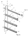
- FIG. 1a shows the fastening device with a plurality of rails 1, 1 ', the horizontal, ie in the transverse direction 11, extend and to which the sliding brackets 2, 2' are fixed, in the retaining clip 13 - see FIG. 1 b - in each case a guide tube 100 is received for a glass fiber strand, which run vertically, ie in the longitudinal direction 10.
- This profile rails 1, 1 ' are screwed with their left end face to the rail leg 17 of an angled, vertically extending receiving plate, inserted through which corresponding through holes 9 in this rail leg 17 from the outside screws and into corresponding areas of the cross section of the rails 1, 1' in be screwed.
- the rail leg 17 is stepped, so that its front edge in the individual areas 4a, b, c, d, in which respective through openings 9 for fixing a rail 1, 1 'are present, have a different distance from the mounting leg 7 and thus also the rails 1, 1 ', since the passage openings 9 always have the same distance from the front edge of the rail leg.
- the rail 1 only a single receiving area 1a in the form of an undercut groove 6, while the rail 1 '- as in the lower part of the FIG. 1a seen - two such superposed receiving areas has, between which there is a divider, which is an integral part of the rail 1 '.
- this receiving area 1 a which is here an undercut groove 6, for inserting the sliding portion 2 b of the sliding brackets 2, in which the local sliding extensions 19 fit positively into the undercut groove 6.
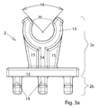
- the sliding clamp 2 comprises - as best the Figures 2 and 3 show - a base plate 12, from which in one direction the sliding extensions 19 protrude - of which in the direction, the transverse direction 11, the rail 1 in this case three Schiebefort instruments 19 are present - and in the other direction of the base plate 12, the C -shaped, by means of a spacer web 14 at a distance from the base plate 12 set retaining clip protrudes, which point away from the base plate 12, that is, the forwardly open, inlet region 20 has.
- the opening angle 16 has a size of 70 ° - 170 °.
- the inlet region 20 is designed conically inwardly to facilitate the insertion of a guide tube 100.
- stiffening webs 15 are arranged in the middle and at an angle thereto, which extend between the base plate 12 and the widest point of the retaining clip 13 and support them against expansion.
- the retaining clip 13 is very stable and when impressing a guide tube 100, the guide tube is forced to make a deformation to an oval, which afterwards, inside Free space of the retaining clip 13, again elastically deformed back to a round cross-section.
- the clip portion 2a with retaining clip 13, spacer web 14 and stiffening webs 15 corresponds to those of the previously described sliding brackets 2, but may have a larger diameter of the retaining clip 13 inside However, in which the sliding extensions 19 must have a central slot for receiving the web between the two receiving areas 1a of the rail 1 '.
- Between two sliding brackets 2 can also be a sliding place holder 3 in the rail 1, 1 'are inserted, the task is to keep two adjacent sliding bracket 2 or 2' in a defined distance from each other.
- FIGS. 4a . b show, the slide space holder 3 from the base plate 12 arranged therewith sliding portion 2b, ie the sliding tongues 19, but without a clamp portion 2a, so that the base plate 12 has a freely accessible front, which is also available for labeling.
- the profile rails 1, 1 ' have except their receiving area, so the undercut groove 6, which is open in the mounted state forward, above and below then each have a mounting portion 1 c, which is also C-shaped in cross section, but with the open side above facing up or down.
- This fastening region 1c serves to screw in the screws inserted through the passage openings 9 of the receiving plate 4, which then can be screwed into the inner circumference of the fastening regions 1c-preferably by self-tapping.
- the length of the profiled rail 1, 1 ' is preferably completely, that is to say completely, filled with sliding clamps 2 and / or sliding place holders 3, and the left end side of the receiving area 1a, ie the groove 6, is closed by the rail limbs 17 of the receiving sheet 4, the right end of the profile rails 1, 1 '- which is not otherwise attached to the distribution cabinet 101 except via the sliding clamps 2 with the guide tubes 100 - must be closed in a different manner.
- FIG. 1b shows, this is done by an identification plate 5, which is placed and fixed to the right in this case end face of the rail 1.
- the identification plate 5 is in this case trough-shaped with an opening facing away from the rail 1 and z. B. can be closed by a transparent lid 18, so that a label behind it is always good and safe from contamination visible, referred to this rail 1 guide tubes 100 and the glass fiber strands recorded therein.
- the identification plate 5 is in the mounted state with the outside of its bottom on the end face of the rail 1, 1 ', that the receiving area 1a, so in this case the undercut groove 6, at least as far covered that slipping out of retaining clips 2 or Sliding place holders 3 is no longer possible.
- the identification plate 5 is fixed by the fact that from the back of the receiving portion 1a of the rail 1 in turn C-shaped in cross section but in this case rearwardly directed, insertion extension 8 is arranged, which is like the mounting portions 1c integrally formed together with the receiving area ,
- an insertion pin 5 a From the back of the bottom of the identification plate 5 is an insertion pin 5 a, which fits into the insertion end 8 in the front side and there latched positively or positively. Further protrusions from the back of the bottom of the identification plate 5 can help in the assembled state to prevent rotation about this insertion pin 5a relative to the rail 1 positively in which they engage in one of the mounting portions 1 c or the groove 6.
- the extension of the base plates 12 in the transverse direction 11, that is, the course direction of the profile rails 1, is preferably the same for all types of sliding brackets 2, 2 '.
- the extent of this base plate 12 in the sliding place holders 3 is preferably the same as in sliding brackets 2, but additional sliding space holder may be present, whose extension of the base plate 12 in this direction is only half the extent of the sliding brackets 2.
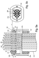
- a retaining nut 22a is screwed from below, which has a matching internal thread in its inner circumference in the upward front region, and at the end face an O-ring 25 or another seal is located, with the further forward screw the retaining nut 22a sealing against the underside of the bottom plate 103 is pressed.
- the sheath ends approximately in the middle of the length of the retaining nut 22a, and from there on, the individual guide tubes 100 without outer sheath and preferably slightly further apart than in the underground cable 110 continue ,
- the lower sealing unit is in the pressure plates 23 a, b and the intermediate plate 24, a central through hole in the size of the fiber optic earth cable 110 is present, through which this is inserted before tightening the pressure screws 27, so that the jacket of the underground cable just above this lower intermediate plate 24 ends.
- the lower pressure plate is integrally formed together with the lower end of the retaining nut 22a, the upper plate is a separate part.
- a plurality of, in particular three or four, pressure screws 27 are arranged around the earth cable or the guide tubes 100 distributed around the earth cable around the pressure screws 27.
Landscapes
- Engineering & Computer Science (AREA)
- Physics & Mathematics (AREA)
- General Engineering & Computer Science (AREA)
- Architecture (AREA)
- General Physics & Mathematics (AREA)
- Optics & Photonics (AREA)
- Mechanical Engineering (AREA)
- Civil Engineering (AREA)
- Structural Engineering (AREA)
- Light Guides In General And Applications Therefor (AREA)
- Clamps And Clips (AREA)
- Supports For Pipes And Cables (AREA)
- Mutual Connection Of Rods And Tubes (AREA)
- Connection Of Plates (AREA)
Claims (18)
- Système modulaire pour fabriquer un dispositif de fixation pour les tubes de guidage (100), s'étendant dans une direction longitudinale (10), de câbles de fibres optiques dans des armoires de distribution de câbles (101), avec- au moins une sorte à chaque fois d'au moins un rail profilé (1) s'étendant dans la direction transversale (11), avec-- une zone de logement (1 a) qui a la forme d'une rainure à contre-dépouille (6) et qui est conçue en forme de C et ouverte vers l'avant dans la forme de section transversale du rail profilé (1) pour loger de manière déplaçable avec concordance de forme des crochets coulissants (2) ou des garde-places (3), et-- à chaque fois une zone de fixation (1c), en forme de C et ouverte vers l'extérieur, au-dessus de la zone de logement (1a) avec ouverture vers le haut et au-dessous de la zone de logement (1a) avec ouverture vers le bas pour visser des vis dans le pourtour intérieur de la zone de fixation (1 c),- différentes sortes à chaque fois de plusieurs crochets coulissants (2), avec-- à chaque fois une zone de crochet (2a) en forme de C avec à chaque fois un diamètre différent pour loger avec concordance de forme un tube de guidage (100) et-- à chaque fois une zone coulissante (2b) qui est adaptée dans la rainure (6) et qui sert à coulisser dans la direction principale, la direction transversale (11) du rail profilé (1),- au moins une sorte à chaque fois de plusieurs garde-places coulissants (3) qui sont adaptés dans la rainure (6) du rail profilé (1) de manière à pouvoir se déplacer dans la direction principale, la direction transversale (11),- au moins une partie de logement (4) avec des ouvertures de passage (9) pour la fixation du rail profilé (1) avec son côté frontal, la partie de logement (4) à l'état monté recouvrant alors au moins la zone de logement (1a) de la surface frontale du rail profilé (1),- au moins une plaque d'identification (5) qui peut être fixée au rail profilé (1) et qui recouvre à l'état monté la zone de logement (1 a) de la surface frontale du rail profilé (1) au moins jusqu'à un point auquel un glissement de crochets coulissants (2) ou de garde-places coulissants (3) hors de la structure n'est plus possible.
- Système modulaire selon la revendication 1,
caractérisé en ce que
le rail profilé (1) comporte plusieurs zones de logement (1a, b) séparées les unes des autres et situées les unes à côté des autres dans la direction principale. - Système modulaire selon l'une des revendications précédentes,
caractérisé en ce que
sur le côté arrière, le rail profilé (1) comporte un prolongement, notamment un prolongement d'insertion (8) en forme de C pour insérer ou visser la plaque d'identification (5). - Système modulaire selon l'une des revendications précédentes,
caractérisé en ce que- la partie de logement, notamment la tôle de logement (4), comporte des ouvertures de passage (9) adaptées, par leurs positions et par leurs distances les unes par rapport aux autres, aux zones de fixation (1c) des rails profilés (1) et/ou- le rail profilé (1) est un profilé extrudé, notamment en métal, notamment en aluminium. - Système modulaire selon l'une des revendications précédentes,
caractérisé en ce que- le crochet coulissant (2) est fabriqué d'une seule pièce et est notamment une pièce moulée par injection en plastique et/ou- le crochet coulissant (2) comporte une plaque de fond (12) à partir de laquelle des prolongements coulissants (19) adaptés dans la zone de logement (1a) dépassent vers l'arrière et le crochet de maintien (13) pour le tube de guidage (100) dépasse vers l'avant. - Système modulaire selon l'une des revendications précédentes,
caractérisé en ce que- le crochet de maintien (13) a une forme en C et est à une certaine distance de la plaque de fond (12) notamment par le biais d'une entretoise (14) et/ou- à côté de l'entretoise (14), des traverses de renfort (15) s'étendent entre la plaque de fond (12) et le crochet de maintien (13) de manière à empêcher tout élargissement du crochet de maintien (13). - Système modulaire selon l'une des revendications précédentes,
caractérisé en ce que- l'angle d'ouverture (10) du crochet de maintien (13) est compris entre 90° et 170°, notamment entre 100° et 130°, et/ou- la zone d'entrée (17) du crochet de maintien (13) est biseautée et se rétrécit en cône vers l'intérieur et/ou l'arête périphérique intérieure du crochet de maintien (13) est biseautée ou arrondie. - Système modulaire selon l'une des revendications précédentes,
caractérisé en ce que- le système modulaire comprend des garde-places coulissants (3) et le dispositif d'écartement (3) comporte une plaque de fond (13) et des prolongements coulissants (19) qui dépassent de celle-ci vers l'arrière et qui sont adaptés dans la zone de logement (1a) du rail profilé (1), et/ou- la plaque d'identification (5) est conçue en forme de cuvette avec au moins un tenon d'insertion (5a) qui dépasse du fond du côté opposé au côté frontal ouvert et qui est adapté par exemple dans le prolongement d'insertion (8) du rail profilé (1). - Système modulaire selon l'une des revendications précédentes,
caractérisé en ce que- la plaque d'identification (5) comprend un couvercle (18) transparent et fermant le côté ouvert et/ou- les garde-places coulissants (3) sont, sur le dessus de la plaque de fond (12), en un matériau sur lequel on peut écrire. - Système modulaire selon l'une des revendications précédentes,
caractérisé en ce que
dans la direction principale du rail profilé (1), les garde-places coulissants (3) ont quant à leur plaque de fond (12) la même longueur ou la moitié de la longueur de la plaque de fond (12) des crochets coulissants (2). - Système modulaire selon l'une des revendications précédentes,
caractérisé en ce que- le système modulaire comporte un manchon de fond (21) pour assurer un passage étanche et sans tension du câble souterrain de fibres optiques (110) par l'ouverture d'introduction (111) de la plaque de fond (113) de l'armoire de distribution (101), et notamment- le manchon de fond (21) est constitué d'une unité de guidage vissée à la plaque de fond (103) et d'au moins une unité de soulagement de tension agencée à l'intérieur. - Système modulaire selon la revendication 11, caractérisé en ce que l'unité de guidage est constituée d'un manchon de maintien (22b) qui s'étend avec son collet à travers l'ouverture d'introduction de boîtier (111) de la plaque de fond (103) et qui s'appuie avec sa flasque élargie sur un côté de celle-ci, qui comporte sur le collet un filetage extérieur (26) ainsi qu'un écrou de maintien (22a) qui comporte un filetage intérieur correspondant (26') et qui peut être vissé sur le collet (22a), ainsi que notamment un joint torique (25) entre l'écrou de maintien (22a) et la plaque de fond (103).
- Système modulaire selon l'une des revendications 11 ou 12, caractérisé en ce que
il est prévu une première unité de soulagement de tension, adaptée dans le pourtour intérieur du manchon de maintien (22b), constituée de deux plaques de pression (23a, b) à une certaine distance axiale l'une de l'autre, d'une plaque intermédiaire (24) élastique agencée entre, des ouvertures de passage alignées pour les tubes de guidage (100) des câbles à fibres optiques étant prévues sur les trois plaques, plusieurs vis de pression (27) qui traversent une plaque de pression (23a) située sur l'extérieur du manchon de fond et qui sont vissées par leur filetage dans l'autre plaque de pression (23b) étant prévues, la plaque de pression extérieure (23a) reposant notamment sur la surface frontale du manchon de maintien (22b). - Système modulaire selon l'une des revendications 11 à 13, caractérisé en ce que- une deuxième unité de soulagement de tension est prévue entre le pourtour extérieur du câble souterrain de fibres optiques (110) et l'écrou de maintien (22a) dans la zone à l'écart du filetage intérieur (26'),- la deuxième unité de soulagement de tension comprenant notamment deux plaques de pression (23a, b) à une certaine distance axiale l'une de l'autre, une plaque intermédiaire (24) élastique agencée entre, avec une ouverture de passage centrale pour le câble souterrain de fibres optiques (110).
- Système modulaire selon la revendication 14, caractérisé en ce que- la plaque de pression (23a), située sur le côté extérieur du manchon de fond (21), de la deuxième unité de soulagement de tension est conçue d'une seule pièce avec l'écrou de maintien (22a), et/ou- l'écrou de maintien a un diamètre intérieur qui, au moins à l'écart du filetage intérieur (26'), est plus grand que le diamètre extérieur du câble souterrain de fibres optiques (110).
- Dispositif de fixation pour les tubes de guidage (100), s'étendant dans la direction longitudinale (10), de câbles à fibres optiques dans des armoires de distribution de câbles (101), fabriqué à partir du système modulaire selon l'une des revendications précédentes, avec- au moins un rail profilé (1) s'étendant dans la direction transversale (11),- plusieurs crochets coulissants (2), pouvant être déplacés avec concordance de forme le long du rail profilé (1), avec une zone de crochet (2a) en forme de C pour un tube de guidage (100) à chaque fois,caractérisé en ce que- le rail profilé (1) est entièrement occupé, dans sa direction principale, avec des crochets coulissants (2) et le cas échéant avec des garde-places coulissants (3),- le rail profilé (1) est vissé seulement par l'un de ses côtés frontaux à une partie de logement, notamment une tôle de logement (4), s'étendant dans la direction longitudinale (10),- l'autre côté frontal du rail profilé (1) est recouvert par une plaque d'identification (5) au moins jusqu'à un point auquel un glissement de crochets coulissants (2) ou de garde-places coulissants (3) hors de la structure n'est plus possible.
- Dispositif de fixation selon la revendication 16,
caractérisé en ce que
la surface frontale, opposée à la partie de logement, du rail profilé (1) est fermée par une plaque d'identification (5) qui est notamment vissée ou enclenchée dans le côté frontal du rail profilé (1). - Dispositif de fixation selon l'une des revendications 16 ou 17,
caractérisé en ce qu'
il est prévu plusieurs rails profilés qui sont positionnés à différentes profondeurs et qui sont aussi montés de préférence à différentes hauteurs.
Priority Applications (1)
| Application Number | Priority Date | Filing Date | Title |
|---|---|---|---|
| PL11186066T PL2450729T3 (pl) | 2010-11-04 | 2011-10-21 | Zestaw do urządzenia do mocowania |
Applications Claiming Priority (2)
| Application Number | Priority Date | Filing Date | Title |
|---|---|---|---|
| DE102010050465 | 2010-11-04 | ||
| DE102011012438.1A DE102011012438B4 (de) | 2010-11-04 | 2011-02-25 | Baukasten für Befestigungsvorrichtung |
Publications (3)
| Publication Number | Publication Date |
|---|---|
| EP2450729A2 EP2450729A2 (fr) | 2012-05-09 |
| EP2450729A3 EP2450729A3 (fr) | 2012-08-08 |
| EP2450729B1 true EP2450729B1 (fr) | 2016-02-10 |
Family
ID=44992559
Family Applications (1)
| Application Number | Title | Priority Date | Filing Date |
|---|---|---|---|
| EP11186066.4A Active EP2450729B1 (fr) | 2010-11-04 | 2011-10-21 | Système modulaire pour un dispositif de fixation |
Country Status (5)
| Country | Link |
|---|---|
| EP (1) | EP2450729B1 (fr) |
| DE (1) | DE102011012438B4 (fr) |
| DK (1) | DK2450729T3 (fr) |
| ES (1) | ES2569855T3 (fr) |
| PL (1) | PL2450729T3 (fr) |
Cited By (2)
| Publication number | Priority date | Publication date | Assignee | Title |
|---|---|---|---|---|
| WO2021148544A1 (fr) * | 2020-01-22 | 2021-07-29 | CommScope Connectivity Belgium BVBA | Unités de terminaison de câble pour des éléments de distribution de fibre optique |
| DE102022120211A1 (de) * | 2022-08-10 | 2024-02-15 | EBG innolab GmbH | Rohrhaltersystem für Verteilerschrank |
Families Citing this family (23)
| Publication number | Priority date | Publication date | Assignee | Title |
|---|---|---|---|---|
| ES2953122T3 (es) | 2013-01-29 | 2023-11-08 | CommScope Connectivity Belgium BVBA | Sistema de distribución de fibra óptica |
| CN103234081A (zh) * | 2013-04-03 | 2013-08-07 | 河南省气象信息网络与技术保障中心 | 网线集线架 |
| AP2015008820A0 (en) | 2013-04-24 | 2015-10-31 | Adc Czech Republic Sro | Optical fiber distribution system |
| HUE053625T2 (hu) | 2013-04-24 | 2021-07-28 | CommScope Connectivity Belgium BVBA | Optikai szálelosztási rendszer |
| AU2014300959B2 (en) | 2013-06-28 | 2018-09-27 | CommScope Connectivity Belgium BVBA | Optical fiber distribution system with staggered cable guides |
| WO2015003989A1 (fr) * | 2013-07-12 | 2015-01-15 | Tyco Electronics Raychem Bvba | Dispositif d'agrafe et de fixation destiné à un élément de câble |
| CN104020540B (zh) * | 2014-05-27 | 2016-08-24 | 烽火通信科技股份有限公司 | 一种智能光缆分纤箱及应用其管理端口的方法 |
| CN105406317A (zh) * | 2015-11-09 | 2016-03-16 | 南宁市正极机电有限公司 | 一种电气设备维修用的电路对接装置 |
| CN105305351B (zh) * | 2015-12-01 | 2018-01-16 | 德特威勒(苏州)电缆系统有限公司 | 一种可以改变理线槽间距的理线架 |
| DE102016222708B4 (de) | 2016-11-18 | 2024-06-06 | Bayerische Motoren Werke Aktiengesellschaft | Aufnahmevorrichtung zur Aufnahme eines leitungsförmigen Bauteils |
| DE102018112217A1 (de) * | 2018-05-22 | 2019-11-28 | Webasto SE | Fahrzeugdachrahmen mit Antriebsrohr für Antriebskabel |
| WO2020043911A1 (fr) | 2018-08-31 | 2020-03-05 | CommScope Connectivity Belgium BVBA | Ensembles bâtis d'éléments de distribution de fibre optique |
| MX2021002249A (es) | 2018-08-31 | 2021-07-15 | CommScope Connectivity Belgium BVBA | Unidades de marco para elementos de distribucion de fibra optica. |
| EP3844973B1 (fr) | 2018-08-31 | 2024-11-06 | CommScope Connectivity Belgium BVBA | Ensembles cadre pour éléments de distribution de fibres optiques |
| EP3844972B1 (fr) | 2018-08-31 | 2022-08-03 | CommScope Connectivity Belgium BVBA | Ensembles cadres pour éléments de distribution de fibres optiques |
| EP3844547A1 (fr) | 2018-08-31 | 2021-07-07 | CommScope Connectivity Belgium BVBA | Assemblage de châssis pour éléments de distribution de fibres optiques |
| WO2020084012A1 (fr) | 2018-10-23 | 2020-04-30 | CommScope Connectivity Belgium BVBA | Ensembles cadre destinés à des éléments de distribution de fibre optique |
| DE202019101080U1 (de) * | 2019-02-25 | 2019-04-05 | Rittal Gmbh & Co. Kg | Schaltschrank mit einer Leerrohreinführung zur Einführung einer Vielzahl Lichtwellenleiter in einen Schaltschrankinnenraum |
| EP4094108B1 (fr) | 2020-01-24 | 2025-06-18 | CommScope Connectivity Belgium BVBA | Éléments de distribution de télécommunications |
| EP4100777A1 (fr) | 2020-02-07 | 2022-12-14 | CommScope Connectivity Belgium BVBA | Agencements de modules de télécommunication |
| DE102020123879B4 (de) | 2020-09-14 | 2022-05-19 | Berthold Sichert Gmbh | Halteclip für ein Glasfaserröhrchen, Befestigungsvorrichtung mit einem Halteclip, Baukasten mit einem Halteclip und Kabelverteilerschrank |
| JP2022155789A (ja) * | 2021-03-31 | 2022-10-14 | コーニング リサーチ アンド ディヴェロップメント コーポレイション | 配線架及びケーブル固定機構 |
| CN118157044B (zh) * | 2024-05-11 | 2024-08-02 | 国网山东省电力公司济宁市任城区供电公司 | 一种电线夹持卡具及使用方法 |
Family Cites Families (13)
| Publication number | Priority date | Publication date | Assignee | Title |
|---|---|---|---|---|
| DE7522695U (de) * | 1975-07-17 | 1976-02-12 | Universa Heizungssysteme Gmbh, 4500 Osnabrueck | Schelle aus kunststoff oder aehnlichem elastischen material zur befestigung von heizungsrohren oder -schlaeuchen, insbesondere fuer fussbodenheizungen |
| DE2619702C2 (de) * | 1976-05-04 | 1984-07-26 | Hilti Ag, Schaan | Schelle zur Aufnahme von Rohren, Kabeln und dgl. |
| DE3242073A1 (de) * | 1982-11-13 | 1984-05-17 | kabelmetal electro GmbH, 3000 Hannover | Durchfuehrung fuer eine elektrische leitung |
| CH661819A5 (de) * | 1986-09-13 | 1987-08-14 | Brugg Ag Kabelwerke | Vorrichtung zum verlegen und aufhaengen von kabeln. |
| DE8712895U1 (de) * | 1987-09-24 | 1987-11-26 | Siemens AG, 1000 Berlin und 8000 München | Führungselement für Leitungen in Gestellen der elektrischen Nachrichtentechnik |
| GB2245019B (en) * | 1990-06-16 | 1994-04-20 | Raymond Guthrie | Retaining clips |
| US6181862B1 (en) * | 1999-03-12 | 2001-01-30 | Siecor Operations Llc | Interbay fiber optic storage unit |
| EP1303020B1 (fr) * | 2001-10-12 | 2007-10-03 | Fred Schmitt | Câblage électrique à dispositif d'atténuation de contraintes de traction |
| US7490727B2 (en) * | 2002-12-23 | 2009-02-17 | Spiers Dennis D | Storage rack |
| DE10310778B4 (de) * | 2003-03-12 | 2010-04-15 | Berthold Sichert Gmbh | Bausatz für Verteilerschränke |
| DE202004012696U1 (de) * | 2004-08-13 | 2004-10-07 | CCS Technology, Inc., Wilmington | Verteilerschrank für Nachrichtenkabel |
| GB2450519A (en) * | 2007-06-28 | 2008-12-31 | Global Emc Solutions Ltd | A cable gland |
| EP2211079A1 (fr) * | 2009-01-23 | 2010-07-28 | AZ Pokorny S.R.O. | Système de fixation pour conduites et procédé de fixation |
-
2011
- 2011-02-25 DE DE102011012438.1A patent/DE102011012438B4/de active Active
- 2011-10-21 EP EP11186066.4A patent/EP2450729B1/fr active Active
- 2011-10-21 DK DK11186066.4T patent/DK2450729T3/en active
- 2011-10-21 PL PL11186066T patent/PL2450729T3/pl unknown
- 2011-10-21 ES ES11186066.4T patent/ES2569855T3/es active Active
Cited By (3)
| Publication number | Priority date | Publication date | Assignee | Title |
|---|---|---|---|---|
| WO2021148544A1 (fr) * | 2020-01-22 | 2021-07-29 | CommScope Connectivity Belgium BVBA | Unités de terminaison de câble pour des éléments de distribution de fibre optique |
| US12174443B2 (en) | 2020-01-22 | 2024-12-24 | CommScope Connectivity Belgium BVBA | Cable termination units for optical fiber distribution elements |
| DE102022120211A1 (de) * | 2022-08-10 | 2024-02-15 | EBG innolab GmbH | Rohrhaltersystem für Verteilerschrank |
Also Published As
| Publication number | Publication date |
|---|---|
| PL2450729T3 (pl) | 2016-07-29 |
| EP2450729A2 (fr) | 2012-05-09 |
| EP2450729A3 (fr) | 2012-08-08 |
| DE102011012438A1 (de) | 2012-05-10 |
| ES2569855T3 (es) | 2016-05-12 |
| DE102011012438B4 (de) | 2016-04-14 |
| DK2450729T3 (en) | 2016-05-02 |
Similar Documents
| Publication | Publication Date | Title |
|---|---|---|
| EP2450729B1 (fr) | Système modulaire pour un dispositif de fixation | |
| DE69412563T2 (de) | Schrank mit Eckverbindung und ein Schaltschrank mit solchen Verbindungen | |
| DE8816805U1 (de) | Bausatz zum Aufbau eines Büroarbeitsplatzes | |
| EP1656720A1 (fr) | Dispositif de reception pour cables optiques et manchon de cable | |
| EP0467066B1 (fr) | Structure de mur-rideau constitué d'éléments | |
| DE19517011A1 (de) | Vorrichtung zur Verbindung von Profilstangen insbesondere für den Möbel- und Gestellbau | |
| DE102007002601A1 (de) | Zaunbefestigungssystem | |
| DE60210151T2 (de) | Spleissschutzmuffe | |
| DE2625321C2 (fr) | ||
| DE102007010042B3 (de) | Verschlusselement | |
| EP2806516A1 (fr) | Bloc d'étanchéité pour des conducteurs individuels | |
| DE102019122106B3 (de) | Zaunerweiterungsvorrichtung | |
| DE2803972C2 (de) | Zähler- und Verteilerschrank aus Kunststoff-Extruderprofilen | |
| DE69635356T2 (de) | Elektrische Steckdose | |
| DE19834372C1 (de) | Profilrohr für die Herstellung kurzzeitiger Aufbauten | |
| WO2004019304A2 (fr) | Systeme de presentation pour ecran | |
| DE69509275T2 (de) | Rohraufhängevorrichtung | |
| DE4290308C2 (de) | Kasten für automatische Sicherungen | |
| DE9406360U1 (de) | Einbaugehäuse für wenigstens ein elektrisches Installationsgerät | |
| DE102020123879B4 (de) | Halteclip für ein Glasfaserröhrchen, Befestigungsvorrichtung mit einem Halteclip, Baukasten mit einem Halteclip und Kabelverteilerschrank | |
| EP3766770B1 (fr) | Guidage de câble pour un vélo | |
| DE10156291B4 (de) | Vorrichtung zur Fixierung von Hausanschlussleitungen | |
| DE8916173U1 (de) | Möbeleckverbinder | |
| WO2017025508A1 (fr) | Panneau mural et système mural pour stand de foire | |
| DE7802731U1 (de) | Zähler- und Verteilerschrank |
Legal Events
| Date | Code | Title | Description |
|---|---|---|---|
| PUAI | Public reference made under article 153(3) epc to a published international application that has entered the european phase |
Free format text: ORIGINAL CODE: 0009012 |
|
| AK | Designated contracting states |
Kind code of ref document: A2 Designated state(s): AL AT BE BG CH CY CZ DE DK EE ES FI FR GB GR HR HU IE IS IT LI LT LU LV MC MK MT NL NO PL PT RO RS SE SI SK SM TR |
|
| AX | Request for extension of the european patent |
Extension state: BA ME |
|
| PUAL | Search report despatched |
Free format text: ORIGINAL CODE: 0009013 |
|
| AK | Designated contracting states |
Kind code of ref document: A3 Designated state(s): AL AT BE BG CH CY CZ DE DK EE ES FI FR GB GR HR HU IE IS IT LI LT LU LV MC MK MT NL NO PL PT RO RS SE SI SK SM TR |
|
| AX | Request for extension of the european patent |
Extension state: BA ME |
|
| RIC1 | Information provided on ipc code assigned before grant |
Ipc: F16L 3/00 20060101ALI20120629BHEP Ipc: G02B 6/44 20060101AFI20120629BHEP |
|
| 17P | Request for examination filed |
Effective date: 20121005 |
|
| 17Q | First examination report despatched |
Effective date: 20140820 |
|
| RIC1 | Information provided on ipc code assigned before grant |
Ipc: H02G 3/32 20060101ALN20150529BHEP Ipc: F16L 3/24 20060101ALN20150529BHEP Ipc: G02B 6/44 20060101AFI20150529BHEP |
|
| GRAP | Despatch of communication of intention to grant a patent |
Free format text: ORIGINAL CODE: EPIDOSNIGR1 |
|
| INTG | Intention to grant announced |
Effective date: 20150716 |
|
| GRAS | Grant fee paid |
Free format text: ORIGINAL CODE: EPIDOSNIGR3 |
|
| GRAA | (expected) grant |
Free format text: ORIGINAL CODE: 0009210 |
|
| AK | Designated contracting states |
Kind code of ref document: B1 Designated state(s): AL AT BE BG CH CY CZ DE DK EE ES FI FR GB GR HR HU IE IS IT LI LT LU LV MC MK MT NL NO PL PT RO RS SE SI SK SM TR |
|
| REG | Reference to a national code |
Ref country code: GB Ref legal event code: FG4D Free format text: NOT ENGLISH |
|
| REG | Reference to a national code |
Ref country code: AT Ref legal event code: REF Ref document number: 774930 Country of ref document: AT Kind code of ref document: T Effective date: 20160215 Ref country code: CH Ref legal event code: EP |
|
| REG | Reference to a national code |
Ref country code: IE Ref legal event code: FG4D Free format text: LANGUAGE OF EP DOCUMENT: GERMAN |
|
| REG | Reference to a national code |
Ref country code: DE Ref legal event code: R096 Ref document number: 502011008842 Country of ref document: DE |
|
| REG | Reference to a national code |
Ref country code: DK Ref legal event code: T3 Effective date: 20160425 |
|
| REG | Reference to a national code |
Ref country code: ES Ref legal event code: FG2A Ref document number: 2569855 Country of ref document: ES Kind code of ref document: T3 Effective date: 20160512 |
|
| REG | Reference to a national code |
Ref country code: PT Ref legal event code: SC4A Free format text: AVAILABILITY OF NATIONAL TRANSLATION Effective date: 20160509 |
|
| REG | Reference to a national code |
Ref country code: NL Ref legal event code: FP |
|
| REG | Reference to a national code |
Ref country code: LT Ref legal event code: MG4D |
|
| REG | Reference to a national code |
Ref country code: CH Ref legal event code: NV Representative=s name: SCHMAUDER AND PARTNER AG PATENT- UND MARKENANW, CH |
|
| REG | Reference to a national code |
Ref country code: NO Ref legal event code: T2 Effective date: 20160210 |
|
| PG25 | Lapsed in a contracting state [announced via postgrant information from national office to epo] |
Ref country code: HR Free format text: LAPSE BECAUSE OF FAILURE TO SUBMIT A TRANSLATION OF THE DESCRIPTION OR TO PAY THE FEE WITHIN THE PRESCRIBED TIME-LIMIT Effective date: 20160210 Ref country code: FI Free format text: LAPSE BECAUSE OF FAILURE TO SUBMIT A TRANSLATION OF THE DESCRIPTION OR TO PAY THE FEE WITHIN THE PRESCRIBED TIME-LIMIT Effective date: 20160210 Ref country code: GR Free format text: LAPSE BECAUSE OF FAILURE TO SUBMIT A TRANSLATION OF THE DESCRIPTION OR TO PAY THE FEE WITHIN THE PRESCRIBED TIME-LIMIT Effective date: 20160511 |
|
| PG25 | Lapsed in a contracting state [announced via postgrant information from national office to epo] |
Ref country code: SE Free format text: LAPSE BECAUSE OF FAILURE TO SUBMIT A TRANSLATION OF THE DESCRIPTION OR TO PAY THE FEE WITHIN THE PRESCRIBED TIME-LIMIT Effective date: 20160210 Ref country code: IS Free format text: LAPSE BECAUSE OF FAILURE TO SUBMIT A TRANSLATION OF THE DESCRIPTION OR TO PAY THE FEE WITHIN THE PRESCRIBED TIME-LIMIT Effective date: 20160610 Ref country code: LV Free format text: LAPSE BECAUSE OF FAILURE TO SUBMIT A TRANSLATION OF THE DESCRIPTION OR TO PAY THE FEE WITHIN THE PRESCRIBED TIME-LIMIT Effective date: 20160210 Ref country code: RS Free format text: LAPSE BECAUSE OF FAILURE TO SUBMIT A TRANSLATION OF THE DESCRIPTION OR TO PAY THE FEE WITHIN THE PRESCRIBED TIME-LIMIT Effective date: 20160210 Ref country code: LT Free format text: LAPSE BECAUSE OF FAILURE TO SUBMIT A TRANSLATION OF THE DESCRIPTION OR TO PAY THE FEE WITHIN THE PRESCRIBED TIME-LIMIT Effective date: 20160210 |
|
| REG | Reference to a national code |
Ref country code: FR Ref legal event code: PLFP Year of fee payment: 6 |
|
| PG25 | Lapsed in a contracting state [announced via postgrant information from national office to epo] |
Ref country code: EE Free format text: LAPSE BECAUSE OF FAILURE TO SUBMIT A TRANSLATION OF THE DESCRIPTION OR TO PAY THE FEE WITHIN THE PRESCRIBED TIME-LIMIT Effective date: 20160210 |
|
| REG | Reference to a national code |
Ref country code: DE Ref legal event code: R097 Ref document number: 502011008842 Country of ref document: DE |
|
| PG25 | Lapsed in a contracting state [announced via postgrant information from national office to epo] |
Ref country code: SK Free format text: LAPSE BECAUSE OF FAILURE TO SUBMIT A TRANSLATION OF THE DESCRIPTION OR TO PAY THE FEE WITHIN THE PRESCRIBED TIME-LIMIT Effective date: 20160210 Ref country code: SM Free format text: LAPSE BECAUSE OF FAILURE TO SUBMIT A TRANSLATION OF THE DESCRIPTION OR TO PAY THE FEE WITHIN THE PRESCRIBED TIME-LIMIT Effective date: 20160210 Ref country code: RO Free format text: LAPSE BECAUSE OF FAILURE TO SUBMIT A TRANSLATION OF THE DESCRIPTION OR TO PAY THE FEE WITHIN THE PRESCRIBED TIME-LIMIT Effective date: 20160210 |
|
| PLBE | No opposition filed within time limit |
Free format text: ORIGINAL CODE: 0009261 |
|
| STAA | Information on the status of an ep patent application or granted ep patent |
Free format text: STATUS: NO OPPOSITION FILED WITHIN TIME LIMIT |
|
| 26N | No opposition filed |
Effective date: 20161111 |
|
| PG25 | Lapsed in a contracting state [announced via postgrant information from national office to epo] |
Ref country code: BG Free format text: LAPSE BECAUSE OF FAILURE TO SUBMIT A TRANSLATION OF THE DESCRIPTION OR TO PAY THE FEE WITHIN THE PRESCRIBED TIME-LIMIT Effective date: 20160510 Ref country code: SI Free format text: LAPSE BECAUSE OF FAILURE TO SUBMIT A TRANSLATION OF THE DESCRIPTION OR TO PAY THE FEE WITHIN THE PRESCRIBED TIME-LIMIT Effective date: 20160210 |
|
| REG | Reference to a national code |
Ref country code: IE Ref legal event code: MM4A |
|
| PG25 | Lapsed in a contracting state [announced via postgrant information from national office to epo] |
Ref country code: LU Free format text: LAPSE BECAUSE OF NON-PAYMENT OF DUE FEES Effective date: 20161021 |
|
| REG | Reference to a national code |
Ref country code: FR Ref legal event code: PLFP Year of fee payment: 7 |
|
| PG25 | Lapsed in a contracting state [announced via postgrant information from national office to epo] |
Ref country code: IE Free format text: LAPSE BECAUSE OF NON-PAYMENT OF DUE FEES Effective date: 20161021 |
|
| PG25 | Lapsed in a contracting state [announced via postgrant information from national office to epo] |
Ref country code: HU Free format text: LAPSE BECAUSE OF FAILURE TO SUBMIT A TRANSLATION OF THE DESCRIPTION OR TO PAY THE FEE WITHIN THE PRESCRIBED TIME-LIMIT; INVALID AB INITIO Effective date: 20111021 Ref country code: CY Free format text: LAPSE BECAUSE OF FAILURE TO SUBMIT A TRANSLATION OF THE DESCRIPTION OR TO PAY THE FEE WITHIN THE PRESCRIBED TIME-LIMIT Effective date: 20160210 |
|
| PG25 | Lapsed in a contracting state [announced via postgrant information from national office to epo] |
Ref country code: MK Free format text: LAPSE BECAUSE OF FAILURE TO SUBMIT A TRANSLATION OF THE DESCRIPTION OR TO PAY THE FEE WITHIN THE PRESCRIBED TIME-LIMIT Effective date: 20160210 Ref country code: MC Free format text: LAPSE BECAUSE OF FAILURE TO SUBMIT A TRANSLATION OF THE DESCRIPTION OR TO PAY THE FEE WITHIN THE PRESCRIBED TIME-LIMIT Effective date: 20160210 Ref country code: MT Free format text: LAPSE BECAUSE OF FAILURE TO SUBMIT A TRANSLATION OF THE DESCRIPTION OR TO PAY THE FEE WITHIN THE PRESCRIBED TIME-LIMIT Effective date: 20160210 Ref country code: TR Free format text: LAPSE BECAUSE OF FAILURE TO SUBMIT A TRANSLATION OF THE DESCRIPTION OR TO PAY THE FEE WITHIN THE PRESCRIBED TIME-LIMIT Effective date: 20160210 |
|
| REG | Reference to a national code |
Ref country code: FR Ref legal event code: PLFP Year of fee payment: 8 |
|
| PG25 | Lapsed in a contracting state [announced via postgrant information from national office to epo] |
Ref country code: AL Free format text: LAPSE BECAUSE OF FAILURE TO SUBMIT A TRANSLATION OF THE DESCRIPTION OR TO PAY THE FEE WITHIN THE PRESCRIBED TIME-LIMIT Effective date: 20160210 |
|
| P01 | Opt-out of the competence of the unified patent court (upc) registered |
Effective date: 20230526 |
|
| PGFP | Annual fee paid to national office [announced via postgrant information from national office to epo] |
Ref country code: PT Payment date: 20241002 Year of fee payment: 14 |
|
| PGFP | Annual fee paid to national office [announced via postgrant information from national office to epo] |
Ref country code: NO Payment date: 20241029 Year of fee payment: 14 |
|
| PGFP | Annual fee paid to national office [announced via postgrant information from national office to epo] |
Ref country code: DK Payment date: 20241025 Year of fee payment: 14 |
|
| PGFP | Annual fee paid to national office [announced via postgrant information from national office to epo] |
Ref country code: BE Payment date: 20241028 Year of fee payment: 14 |
|
| PGFP | Annual fee paid to national office [announced via postgrant information from national office to epo] |
Ref country code: GB Payment date: 20241028 Year of fee payment: 14 |
|
| PGFP | Annual fee paid to national office [announced via postgrant information from national office to epo] |
Ref country code: FR Payment date: 20241025 Year of fee payment: 14 |
|
| PGFP | Annual fee paid to national office [announced via postgrant information from national office to epo] |
Ref country code: CZ Payment date: 20241004 Year of fee payment: 14 |
|
| PGFP | Annual fee paid to national office [announced via postgrant information from national office to epo] |
Ref country code: IT Payment date: 20241021 Year of fee payment: 14 Ref country code: ES Payment date: 20241104 Year of fee payment: 14 |
|
| REG | Reference to a national code |
Ref country code: CH Ref legal event code: U11 Free format text: ST27 STATUS EVENT CODE: U-0-0-U10-U11 (AS PROVIDED BY THE NATIONAL OFFICE) Effective date: 20251101 |
|
| PGFP | Annual fee paid to national office [announced via postgrant information from national office to epo] |
Ref country code: NL Payment date: 20251026 Year of fee payment: 15 |
|
| PGFP | Annual fee paid to national office [announced via postgrant information from national office to epo] |
Ref country code: DE Payment date: 20251029 Year of fee payment: 15 |
|
| PGFP | Annual fee paid to national office [announced via postgrant information from national office to epo] |
Ref country code: AT Payment date: 20251029 Year of fee payment: 15 |
|
| PGFP | Annual fee paid to national office [announced via postgrant information from national office to epo] |
Ref country code: CH Payment date: 20251101 Year of fee payment: 15 |
|
| PGFP | Annual fee paid to national office [announced via postgrant information from national office to epo] |
Ref country code: PL Payment date: 20251014 Year of fee payment: 15 |