EP2232624B1 - Vorrichtung zur signalübermittlung für einen mobilen antennenpositionierer - Google Patents
Vorrichtung zur signalübermittlung für einen mobilen antennenpositionierer Download PDFInfo
- Publication number
- EP2232624B1 EP2232624B1 EP08868353A EP08868353A EP2232624B1 EP 2232624 B1 EP2232624 B1 EP 2232624B1 EP 08868353 A EP08868353 A EP 08868353A EP 08868353 A EP08868353 A EP 08868353A EP 2232624 B1 EP2232624 B1 EP 2232624B1
- Authority
- EP
- European Patent Office
- Prior art keywords
- positioner
- waveguide
- wave guide
- antenna
- movement
- Prior art date
- Legal status (The legal status is an assumption and is not a legal conclusion. Google has not performed a legal analysis and makes no representation as to the accuracy of the status listed.)
- Not-in-force
Links
- 230000033001 locomotion Effects 0.000 claims abstract description 22
- 238000005452 bending Methods 0.000 claims abstract description 10
- RYGMFSIKBFXOCR-UHFFFAOYSA-N Copper Chemical compound [Cu] RYGMFSIKBFXOCR-UHFFFAOYSA-N 0.000 claims description 3
- 239000000956 alloy Substances 0.000 claims description 3
- 229910045601 alloy Inorganic materials 0.000 claims description 3
- 229910052790 beryllium Inorganic materials 0.000 claims description 3
- ATBAMAFKBVZNFJ-UHFFFAOYSA-N beryllium atom Chemical compound [Be] ATBAMAFKBVZNFJ-UHFFFAOYSA-N 0.000 claims description 3
- 230000000903 blocking effect Effects 0.000 claims description 3
- 229910052802 copper Inorganic materials 0.000 claims description 3
- 239000010949 copper Substances 0.000 claims description 3
- 230000000712 assembly Effects 0.000 claims 3
- 238000000429 assembly Methods 0.000 claims 3
- 230000006854 communication Effects 0.000 abstract description 2
- 238000004891 communication Methods 0.000 abstract description 2
- 238000004519 manufacturing process Methods 0.000 abstract description 2
- 238000006073 displacement reaction Methods 0.000 description 5
- 239000000969 carrier Substances 0.000 description 3
- 238000003780 insertion Methods 0.000 description 3
- 230000037431 insertion Effects 0.000 description 3
- 230000000694 effects Effects 0.000 description 2
- 239000000463 material Substances 0.000 description 2
- 230000008901 benefit Effects 0.000 description 1
- 230000007175 bidirectional communication Effects 0.000 description 1
- 230000005540 biological transmission Effects 0.000 description 1
- 230000015556 catabolic process Effects 0.000 description 1
- 230000008859 change Effects 0.000 description 1
- 238000006731 degradation reaction Methods 0.000 description 1
- 238000010586 diagram Methods 0.000 description 1
- 230000003100 immobilizing effect Effects 0.000 description 1
- 230000006872 improvement Effects 0.000 description 1
- 238000002955 isolation Methods 0.000 description 1
- 238000012423 maintenance Methods 0.000 description 1
- 230000007246 mechanism Effects 0.000 description 1
- 230000003449 preventive effect Effects 0.000 description 1
- 238000007665 sagging Methods 0.000 description 1
- 230000008054 signal transmission Effects 0.000 description 1
- 239000000725 suspension Substances 0.000 description 1
- 230000035899 viability Effects 0.000 description 1
Images


Classifications
-
- H—ELECTRICITY
- H01—ELECTRIC ELEMENTS
- H01P—WAVEGUIDES; RESONATORS, LINES, OR OTHER DEVICES OF THE WAVEGUIDE TYPE
- H01P1/00—Auxiliary devices
- H01P1/02—Bends; Corners; Twists
- H01P1/022—Bends; Corners; Twists in waveguides of polygonal cross-section
-
- H—ELECTRICITY
- H01—ELECTRIC ELEMENTS
- H01Q—ANTENNAS, i.e. RADIO AERIALS
- H01Q19/00—Combinations of primary active antenna elements and units with secondary devices, e.g. with quasi-optical devices, for giving the antenna a desired directional characteristic
- H01Q19/10—Combinations of primary active antenna elements and units with secondary devices, e.g. with quasi-optical devices, for giving the antenna a desired directional characteristic using reflecting surfaces
- H01Q19/12—Combinations of primary active antenna elements and units with secondary devices, e.g. with quasi-optical devices, for giving the antenna a desired directional characteristic using reflecting surfaces wherein the surfaces are concave
Definitions
- the present invention relates to a signal routing device for a mobile antenna positioner.
- the invention applies in particular to mobile antenna communication systems, and more particularly to the production of antenna stations comprising wide-displacement antenna positioners in the field.
- antenna systems used in bidirectional communications between two mobile carriers are generally provided with a tracking function, the antenna of each of said carriers then having to cover a large pointing surface, so that the radio axes of Each antenna remains oriented vis-à-vis, regardless of the movements of the carriers.
- an antenna system comprises a positioner, that is to say an automaton comprising a mobile part on which the antenna is fixed.
- a first category of positioners makes it possible to orient the antenna by rotating it, on the one hand, around a vertical axis to modify the angle of bearing and, on the other hand, around a horizontal axis to change the elevation angle.
- the signals transmitted and / or received by the mobile antenna are transmitted to a fixed part, for example at the foot of the positioner, via a waveguide.
- the antennary system has a large displacement in the bearing, or even infinite deposit, in other words, when it allows the antenna to rotate indefinitely around the vertical axis, then the use of rotating collectors and / or rotating joints at level of the junction of the waveguide with the fixed part is necessary, so as to avoid submitting the waveguide torsion forces that would damage it.
- a disadvantage of such antenna systems is their high cost of implementation.
- the prior art US 4,876,553 discloses an antenna feed guide rotation system.
- a second category of positioners made on the principle of a Cardan suspension, eliminates collectors and rotating joints.
- These improved positioners include a pointing device without dead point based on a pantograph mechanism; they will be qualified later as “pantograph positioners”.
- waveguides that are sufficiently flexible and accept torsional movements are used.
- waveguides consist of a discontinuous structure, often based on nested scales that cause reliability problems. Indeed, the structure of such a waveguide wears very quickly or even breaks under the effect of repeated twisting movements applied to it. Also, the life of the waveguide is short, which imposes regular preventive replacements. In addition, significant insertion losses and intermodulation products occur when using this type of waveguide. In emission, the powers are then strongly limited.
- An object of the invention is to propose means making it possible to convey signals between the antenna and the foot of a positioner with a large clearance displacement by limiting the insertion losses, the degradation of the signals received and the problems of mechanical viability.
- the subject of the invention is a device for routing microwave signals for an antenna positioner, said positioner being a positioner with a large displacement in the field comprising a fixed part and a mobile part supporting the antenna, the moving part.
- said device comprising a waveguide with a conductive structure a first end of which is connected to the antenna, a second end being connected to the fixed part of the positioner, said device being characterized in that the waveguide is of continuous structure, having an upper end, a lower end and a or several sets of ball joints, the waveguide thus substantially forming an "S", each of its ends being fixed by means allowing a debate waveguide to limit the bending forces of said guide during movements of the positioner.
- the antenna positioner is a pantograph type antenna positioner.
- the means for fixing the waveguide comprise at least one support, locking means and one or more sets of ball joints fixed on said support, the end of the waveguide being kept substantially stationary relative to the support by the blocking means, the waveguide being inserted into said sets of ball joints in order to stabilize the waveguide while giving it a deflection.
- the device comprises at least one spring, the spring being attached to the waveguide by cable clamps.
- the signals conveyed by the waveguide are microwave signals.
- the waveguide is electroformed and made of an alloy comprising beryllium and copper, this material being well adapted to transmissions of microwave signals, and being also adapted to undergo bending along its structure.
- the waveguide has a bellows structure, the waveguide can be alternately deformed along a first axis of rotation and a second axis of rotation, the waveguide can not be deformed under the effect of a twisting motion.
- the inner wall of the waveguide is smooth and has no roughness or opening.
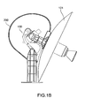
- the moving part 300 of the positioner 100 moves around two axes of rotation X and Y, represented in dotted lines on the figure 2 .
- the upper end 200a of the waveguide 200 which is fixed on the movable part 300 of the positioner 100 thanks to the first fastening means 201, is maintained substantially parallel to the second axis of rotation Y of the positioner, this second axis of rotation Y being itself subjected to a rotational movement about the first axis of rotation X.
- the lower end 200b of the waveguide 200 is held in a fixed position by the second fastening means 202a, 202b, said low end being maintained in the example, substantially horizontally.
- the second fixing means 202a, 202b comprise a first point of attachment 202a allowing a freedom of movement to the waveguide 200, and a second attachment point 202b, placed below the first 202a, for immobilizing the low end 200b of the waveguide 200.
- the waveguide 200 is held by three attachment points 201, 202a, 202b; it substantially forms an S between its upper end 200a and its lower end 200b, this S being deformed according to the movements of the movable part 300 of the positioner 100, alternately in a movement around the first axis of rotation X and around the second axis of Y rotation.
- the high end 200a of the waveguide 200 is attached to the positioner fork 203a, while the low end 200b of the waveguide 200 is attached to the riser 204 of the positioner 100 .
- one or more springs are contiguous to the waveguide 200, to prevent sagging of said guide 200 on itself, because of its own weight, and thus better distribute the mechanical stresses applied to the waveguide 200.
- These springs can be distributed sporadically on the waveguide 200 or extend over its entire length, the stiffness of a spring being chosen in particular according to the weight of the waveguide 200, the size of the waveguide, and the size of the positioner 100.
- the springs are slidably attached only along a plane of the guide through flexible fasteners, such as, for example, plastic cable ties.
- the continuous character of the structure of the waveguide 200 - which makes it possible to obtain good performance in terms of signal transmission - makes it necessary to design specific fastening means to limit the mechanical forces applied to it during the movement of the waveguide. positioner 100.
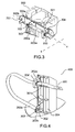
- the figure 3 present, for the embodiment of the figure 2 , a detail of the fastening means 201 of the signal conveying device on the upper mobile part 300 of the positioner.
- These fastening means 201 comprise a support 301 fixed to the mobile high part 300 of the positioner, which, in the example, is the fork 203a.
- the support 301 is a rectangular rigid plate whose wall is fixed on the fork 203a of the positioner 100, the support 301 thus forming a plane orthogonal to the first axis of rotation X.
- Brackets 302 are fixed on the opposite wall of the support 301, the two orthogonal planes 302a, 302b formed by the walls of each bracket 302 themselves being orthogonal to the plane formed by the two axes. X and Y rotation.
- the first wall 302a of each bracket 302 is contiguous to the support 301, while the second wall 302b of the bracket 302 is orthogonal to the second axis of rotation Y.
- a flange 303 integral with the waveguide 200 is placed on the second wall of each bracket 302, so that the waveguide 200 is gripped by each of the flanges 303 along the support 301 and its upper end 200a is held fixed relative to the moving part 300 of the positioner 100, to connect to the antenna 101 ( Figures 1A and 1B ).
- the upper end 200a of the waveguide 200 is held stationary relative to the mobile part 300 of the positioner 100 while the lower part 200b ( figure 4 ) of the waveguide 200 remaining fixed, the waveguide 200 must withstand bending stresses due to the movements of the positioner 100, both around the first axis of rotation X and around the second axis of rotation Y. to limit these bending forces, the waveguide 200 is inserted into one or more sets of ball joints 304, placed in the extension of the brackets 302, along the support 301. In this way, the waveguide 200 is maintained in place while having a travel allowing it to better withstand the bending imposed by the movement of the positioner 100 and simultaneously reduce the stresses applied to the flange 303.
- the spacings between the sets of ball joints 304 can be adapted depending, in particular on the length of the waveguide 200 and its flexibility characteristics.
- the figure 4 present, for the embodiment of the figure 2 a detail of the fixing means 202a, 202b of the signal routing device on the lower part 400 of the positioner 100.
- the fastening means 202a, 202b comprise a first portion 202a located substantially above a second portion 202b.
- the first part 202a of the fixing means 202a, 202b comprises a ball joint assembly 304 'fixed on a support 301' and the second part 202b comprises a fixing flange 303 'fixed on a bracket 302', which is fixed to a support 301 "
- the waveguide 200 is maintained by the ball joint 304 'of the first part 202a and the lower end 200b of the waveguide 200 is fixed to the second part 202b via the fixing flange 303', so that the guide Wave 200 substantially describes a half loop between the first portion 202a and the second portion 202b.
- the fixing means 202 of the signal routing device on the lower part 400 of the positioner 100 are similar to those presented in FIG. figure 3 . They also comprise one or more brackets 302 "substantially aligned on a support 301".
- the waveguide 200 is shown in slight recess with respect to the bracket 302.
- the low end 200b of the waveguide 200 is fixed to the bracket 302 "by means of a fastening flange. 303 ".
- the waveguide 200 is also stabilized with one or more sets of 304" ball joints to give it a travel to limit the bending forces applied to it, as in the figure 3 and to reduce the force applied on the fastening flange 303 ".
- the figure 6 illustrates the structure of the waveguide 200, with a cross section 6A and a perspective view 6B.
- the waveguide 200 has a continuous structure, ie unlike a conventional structure formed by a plurality of associated elements, the waveguide 200 used in the signal routing device according to the invention is formed of only one part, without opening or asperity on its inner wall.
- the waveguide 200 comprises a bellows structure, of rectangular section, with a conductive inner wall, here in an alloy comprising beryllium and copper.
- the waveguide is electroformed.
- the waveguide 200 used in the present invention can not, because of its continuous nature, be subjected to a torsion movement at the same point, that is to say to undergo two orthogonal flexions at the same point. Also, the waveguide 200, to allow nevertheless to adapt to the mechanical stresses imposed by the movement of the positioner 100 is adapted undergo flexing of different directions in several successive locations, particularly thanks to the material used and its bellows structure.
- the length of the waveguide 200 is to be chosen so as to minimize the bending forces applied to it; thus a waveguide 200 too short, for example, could lead to mechanical breaks.
- a signal routing device makes it possible to reduce the insertion losses, to guarantee the isolation of the waveguide over time and not to generate intermodulation products towards the input signal. outside the waveguide especially for microwave signals of high power.
- the attachment means employed and despite the continuous nature of the waveguide structure, the latter is not subjected to excessive bending forces, thus ensuring a good friability of the device.
- the signal routing device according to the invention is particularly suitable for pantograph antenna positioners and ensures an infinitely rotational coverage of the positioner deflection zone. Nevertheless, it can also be mounted on positioners of different types, including turret-type positioners with large displacement in the bearing.
Landscapes
- Variable-Direction Aerials And Aerial Arrays (AREA)
- Waveguide Connection Structure (AREA)
- Input Circuits Of Receivers And Coupling Of Receivers And Audio Equipment (AREA)
- Details Of Aerials (AREA)
- Radar Systems Or Details Thereof (AREA)
- Control Of Conveyors (AREA)
- Support Of Aerials (AREA)
Claims (6)
- Vorrichtung zum Übertragen von Hyperfrequenzsignalen für den Positionierer (100) einer Antenne (101), wobei der Positionierer (100) einen großen Azimutbereich hat, umfassend einen festen Teil (400) und einen beweglichen Teil (300), der die Antenne (101) trägt, wobei der bewegliche Teil so ausgelegt ist, dass er sich zum zwei Drehachsen X und Y bewegen kann, wobei die zweite Drehachse Y so konfiguriert ist, dass sie eine Drehbewegung um die erste Drehachse X erfährt, wobei die Vorrichtung einen Wellenleiter (200) mit einer leitenden Struktur umfasst, von der ein erstes Ende (200a) mit der Antenne und ein zweites Ende (200b) mit dem festen Teil (400) des Positionierers verbunden sind, wobei die Vorrichtung dadurch gekennzeichnet ist, dass der Wellenleiter (200) eine kontinuierliche Struktur hat, die ein oberes Ende (200a), ein unteres Ende (200b) und ein oder mehrere Kugelgelenksätze (304, 304') umfasst, wobei der Wellenleiter (200) somit im Wesentlichen eine "S"-Form bildet, wobei jedes seiner Enden (200a, 200b) mit Mitteln (201, 202) befestigt ist, die einen Bewegungsbereich für den Wellenleiter (200) bieten, um die Biegekräfte des Leiters bei Bewegungen des Positionierers zu begrenzen,
- Vorrichtung nach einem der vorherigen Ansprüche, dadurch gekennzeichnet, dass die Mittel (201, 202) zum Befestigen des Wellenleiters wenigstens einen Träger (301, 301'), Sperrmittel (302, 303, 302', 303') sowie ein oder mehrere an dem Träger (301, 301') befestigte Kugelgelenksätze (304, 304') umfassen, wobei das Ende (200a, 200b) des Wellenleiters (200) von den Sperrmitteln (302, 303) im Wesentlichen unbeweglich relativ zum Träger (301, 301') gehalten wird, wobei der Wellenleiter (200) in die Kugelgelenksätze (304, 304') eingesetzt wird, um den Wellenleiter (200) zu stabilisieren und ihm dabei einen Bewegungsbereich zu geben.
- Vorrichtung nach einem der vorherigen Ansprüche, dadurch gekennzeichnet, dass sie wenigstens eine Feder umfassst, wobei die Feder mit mehreren Kabelklemmen am Wellenleiter (200) befestigt wird,
- Vorrichtung nach einem der vorherigen Ansprüche, dadurch gekennzeichnet, dass der Wellenleiter (200) aus einer Beryllium und Kupfer umfassenden Legierung galvanogeformt ist.
- Vorrichtung nach einem der vorherigen Ansprüche, dadurch gekennzeichnet, dass der Wellenleiter (200) eine Balgstruktur hat.
- Vorrichtung nach einem der vorherigen Ansprüche, dadurch gekennzeichnet, dass die Innenwand des Wellenleiters (200) glatt ist und keine Unregelmäßigkeiten oder Öffnungen aufweist.
Applications Claiming Priority (2)
| Application Number | Priority Date | Filing Date | Title |
|---|---|---|---|
| FR0709053A FR2925769B1 (fr) | 2007-12-21 | 2007-12-21 | Dispositif d'acheminement de signaux pour positionneur d'antenne mobile. |
| PCT/EP2008/067650 WO2009083440A1 (fr) | 2007-12-21 | 2008-12-16 | Dispositif d'acheminement de signaux pour positionneur d'antenne mobile |
Publications (2)
| Publication Number | Publication Date |
|---|---|
| EP2232624A1 EP2232624A1 (de) | 2010-09-29 |
| EP2232624B1 true EP2232624B1 (de) | 2011-08-31 |
Family
ID=39619207
Family Applications (1)
| Application Number | Title | Priority Date | Filing Date |
|---|---|---|---|
| EP08868353A Not-in-force EP2232624B1 (de) | 2007-12-21 | 2008-12-16 | Vorrichtung zur signalübermittlung für einen mobilen antennenpositionierer |
Country Status (7)
| Country | Link |
|---|---|
| US (1) | US8547290B2 (de) |
| EP (1) | EP2232624B1 (de) |
| AT (1) | ATE522948T1 (de) |
| ES (1) | ES2370189T3 (de) |
| FR (1) | FR2925769B1 (de) |
| IL (1) | IL206517A (de) |
| WO (1) | WO2009083440A1 (de) |
Families Citing this family (4)
| Publication number | Priority date | Publication date | Assignee | Title |
|---|---|---|---|---|
| US9561730B2 (en) | 2010-04-08 | 2017-02-07 | Qualcomm Incorporated | Wireless power transmission in electric vehicles |
| US10343535B2 (en) | 2010-04-08 | 2019-07-09 | Witricity Corporation | Wireless power antenna alignment adjustment system for vehicles |
| US9979082B2 (en) * | 2015-08-10 | 2018-05-22 | Viasat, Inc. | Method and apparatus for beam-steerable antenna with single-drive mechanism |
| JP2024508790A (ja) | 2021-02-22 | 2024-02-28 | オフワールド,インコーポレイテッド | ロボットアーム導波管を用いたマイクロ波ベースの採掘システム及び方法 |
Family Cites Families (12)
| Publication number | Priority date | Publication date | Assignee | Title |
|---|---|---|---|---|
| FR1245442A (fr) | 1960-01-21 | 1960-11-04 | Guide d'onde métallique flexible sans soudure | |
| CH493110A (de) * | 1968-12-07 | 1970-06-30 | Telefunken Patent | Richtantenne |
| DE3740651A1 (de) * | 1987-12-01 | 1989-06-22 | Messerschmitt Boelkow Blohm | Vorrichtung zur einstellung der polarisationsebene |
| FR2676598B1 (fr) * | 1991-05-14 | 1993-07-23 | Thomson Csf | Liaison hyperfrequence mobile a guide d'ondes. |
| US5543808A (en) * | 1995-05-24 | 1996-08-06 | The United States Of America As Represented By The Secretary Of The Army | Dual band EHF, VHF vehicular whip antenna |
| FR2769969B1 (fr) | 1997-10-17 | 2000-01-14 | Acc Ingenierie & Maintenance | Mecanisme de pointage a deux mouvements de rotation independants, sans point mort |
| US6577282B1 (en) * | 2000-07-19 | 2003-06-10 | Hughes Electronics Corporation | Method and apparatus for zooming and reconfiguring circular beams for satellite communications |
| GB0122357D0 (en) * | 2001-09-15 | 2001-11-07 | Secr Defence | Sub-surface radar imaging |
| US7079739B1 (en) * | 2003-11-28 | 2006-07-18 | Peter Vitruk | Flexible hollow waveguide and method for its manufacture |
| US6995638B1 (en) * | 2003-12-24 | 2006-02-07 | Lockheed Martin Corporation | Structural augmentation for flexible connector |
| US7301504B2 (en) * | 2004-07-14 | 2007-11-27 | Ems Technologies, Inc. | Mechanical scanning feed assembly for a spherical lens antenna |
| US8427384B2 (en) * | 2007-09-13 | 2013-04-23 | Aerosat Corporation | Communication system with broadband antenna |
-
2007
- 2007-12-21 FR FR0709053A patent/FR2925769B1/fr not_active Expired - Fee Related
-
2008
- 2008-12-16 AT AT08868353T patent/ATE522948T1/de not_active IP Right Cessation
- 2008-12-16 EP EP08868353A patent/EP2232624B1/de not_active Not-in-force
- 2008-12-16 WO PCT/EP2008/067650 patent/WO2009083440A1/fr not_active Ceased
- 2008-12-16 US US12/809,995 patent/US8547290B2/en not_active Expired - Fee Related
- 2008-12-16 ES ES08868353T patent/ES2370189T3/es active Active
-
2010
- 2010-06-21 IL IL206517A patent/IL206517A/en active IP Right Grant
Also Published As
| Publication number | Publication date |
|---|---|
| US20110095959A1 (en) | 2011-04-28 |
| IL206517A0 (en) | 2010-12-30 |
| IL206517A (en) | 2014-11-30 |
| WO2009083440A1 (fr) | 2009-07-09 |
| FR2925769B1 (fr) | 2010-05-21 |
| EP2232624A1 (de) | 2010-09-29 |
| ES2370189T3 (es) | 2011-12-13 |
| US8547290B2 (en) | 2013-10-01 |
| FR2925769A1 (fr) | 2009-06-26 |
| ATE522948T1 (de) | 2011-09-15 |
Similar Documents
| Publication | Publication Date | Title |
|---|---|---|
| EP3015368B1 (de) | Befestigungsvorrichtung für einen motor eines luftfahrzeugs, und entsprechendes luftfahrzeug | |
| EP2232624B1 (de) | Vorrichtung zur signalübermittlung für einen mobilen antennenpositionierer | |
| EP2783989B1 (de) | Ausfahrbarer Mast mit autonomer spontaner Ausfahrbewegung, und Satellit, der mit mindestens einem solchen Mast ausgestattet ist | |
| EP0519775A1 (de) | In Betriebszeit rekonfigurierbarer Antennenreflektor | |
| FR2773890A1 (fr) | Ensemble integre et compact de montage isostatique et de correction de position d'un organe, tel qu'un miroir, d'un telescope spatial | |
| EP1188668B1 (de) | Ausrichtungsvorrichung und Bordausrichtungsanlage | |
| CA2839809C (fr) | Procede d'ouverture d'un dome de protection, en particulier d'un radome, et radome equipe d'un pantographe de mise en oeuvre | |
| EP1796209A1 (de) | Richtfunkantenne mit Schutzhaube und Verfahren zu ihrem Zusammenbau | |
| FR2685131A1 (fr) | Antenne de reception a reflecteur fixe pour plusieurs faisceaux de satellite. | |
| EP4151461B1 (de) | System zur kompensation der thermischen ausdehnung eines kabels mit bimetallelementen | |
| EP3910739A1 (de) | Automatisch ausklappbare funkfrequenzantenne | |
| EP0030180A1 (de) | Röhrenverbindungsvorrichtung | |
| FR2905039A1 (fr) | Support pour fixer des cables electriques sur une structure | |
| FR2850174A1 (fr) | Systemes asservis d'actionnement | |
| EP0514251B1 (de) | Hyperfrequente bewegbare Wellenleiterverbindung | |
| FR2470453A2 (fr) | Coupleur directionnel a amortissement de couplage variable | |
| EP3900107B1 (de) | Marineplattformmast | |
| EP2843760B1 (de) | Montagesystem einer Kompaktantenne | |
| EP3087635B1 (de) | Vorrichtung zur ferngesteuerten positionierung einer relaisantenne | |
| EP1260462B1 (de) | Tragrahmen für einer Bandförderer und Bandförderer mit einem solchen Rahmen | |
| EP3906971B1 (de) | Schutzvorrichtung für seil und schutzsystem | |
| EP3842597B1 (de) | Gelenkverbindungssystem für tragende elemente | |
| EP2226896B1 (de) | Multiband-Rundstrahler | |
| FR3151103A1 (fr) | Dispositif d'ajustement de position à réduction cinématique | |
| WO2005081357A1 (fr) | Plateforme pour pylone de diffusion hertzienne et pylone de diffusion hertzienne muni d’une telle plateforme |
Legal Events
| Date | Code | Title | Description |
|---|---|---|---|
| PUAI | Public reference made under article 153(3) epc to a published international application that has entered the european phase |
Free format text: ORIGINAL CODE: 0009012 |
|
| 17P | Request for examination filed |
Effective date: 20100720 |
|
| AK | Designated contracting states |
Kind code of ref document: A1 Designated state(s): AT BE BG CH CY CZ DE DK EE ES FI FR GB GR HR HU IE IS IT LI LT LU LV MC MT NL NO PL PT RO SE SI SK TR |
|
| AX | Request for extension of the european patent |
Extension state: AL BA MK RS |
|
| 17Q | First examination report despatched |
Effective date: 20101201 |
|
| GRAP | Despatch of communication of intention to grant a patent |
Free format text: ORIGINAL CODE: EPIDOSNIGR1 |
|
| GRAJ | Information related to disapproval of communication of intention to grant by the applicant or resumption of examination proceedings by the epo deleted |
Free format text: ORIGINAL CODE: EPIDOSDIGR1 |
|
| GRAP | Despatch of communication of intention to grant a patent |
Free format text: ORIGINAL CODE: EPIDOSNIGR1 |
|
| DAX | Request for extension of the european patent (deleted) | ||
| GRAS | Grant fee paid |
Free format text: ORIGINAL CODE: EPIDOSNIGR3 |
|
| GRAA | (expected) grant |
Free format text: ORIGINAL CODE: 0009210 |
|
| AK | Designated contracting states |
Kind code of ref document: B1 Designated state(s): AT BE BG CH CY CZ DE DK EE ES FI FR GB GR HR HU IE IS IT LI LT LU LV MC MT NL NO PL PT RO SE SI SK TR |
|
| REG | Reference to a national code |
Ref country code: GB Ref legal event code: FG4D Free format text: NOT ENGLISH Ref country code: CH Ref legal event code: EP |
|
| REG | Reference to a national code |
Ref country code: IE Ref legal event code: FG4D Free format text: LANGUAGE OF EP DOCUMENT: FRENCH |
|
| REG | Reference to a national code |
Ref country code: DE Ref legal event code: R096 Ref document number: 602008009423 Country of ref document: DE Effective date: 20111201 |
|
| REG | Reference to a national code |
Ref country code: ES Ref legal event code: FG2A Ref document number: 2370189 Country of ref document: ES Kind code of ref document: T3 Effective date: 20111213 |
|
| REG | Reference to a national code |
Ref country code: NL Ref legal event code: VDEP Effective date: 20110831 |
|
| LTIE | Lt: invalidation of european patent or patent extension |
Effective date: 20110831 |
|
| PG25 | Lapsed in a contracting state [announced via postgrant information from national office to epo] |
Ref country code: LT Free format text: LAPSE BECAUSE OF FAILURE TO SUBMIT A TRANSLATION OF THE DESCRIPTION OR TO PAY THE FEE WITHIN THE PRESCRIBED TIME-LIMIT Effective date: 20110831 Ref country code: NL Free format text: LAPSE BECAUSE OF FAILURE TO SUBMIT A TRANSLATION OF THE DESCRIPTION OR TO PAY THE FEE WITHIN THE PRESCRIBED TIME-LIMIT Effective date: 20110831 Ref country code: HR Free format text: LAPSE BECAUSE OF FAILURE TO SUBMIT A TRANSLATION OF THE DESCRIPTION OR TO PAY THE FEE WITHIN THE PRESCRIBED TIME-LIMIT Effective date: 20110831 Ref country code: SE Free format text: LAPSE BECAUSE OF FAILURE TO SUBMIT A TRANSLATION OF THE DESCRIPTION OR TO PAY THE FEE WITHIN THE PRESCRIBED TIME-LIMIT Effective date: 20110831 Ref country code: FI Free format text: LAPSE BECAUSE OF FAILURE TO SUBMIT A TRANSLATION OF THE DESCRIPTION OR TO PAY THE FEE WITHIN THE PRESCRIBED TIME-LIMIT Effective date: 20110831 Ref country code: IS Free format text: LAPSE BECAUSE OF FAILURE TO SUBMIT A TRANSLATION OF THE DESCRIPTION OR TO PAY THE FEE WITHIN THE PRESCRIBED TIME-LIMIT Effective date: 20111231 Ref country code: NO Free format text: LAPSE BECAUSE OF FAILURE TO SUBMIT A TRANSLATION OF THE DESCRIPTION OR TO PAY THE FEE WITHIN THE PRESCRIBED TIME-LIMIT Effective date: 20111130 |
|
| REG | Reference to a national code |
Ref country code: AT Ref legal event code: MK05 Ref document number: 522948 Country of ref document: AT Kind code of ref document: T Effective date: 20110831 |
|
| PG25 | Lapsed in a contracting state [announced via postgrant information from national office to epo] |
Ref country code: CY Free format text: LAPSE BECAUSE OF FAILURE TO SUBMIT A TRANSLATION OF THE DESCRIPTION OR TO PAY THE FEE WITHIN THE PRESCRIBED TIME-LIMIT Effective date: 20110831 Ref country code: AT Free format text: LAPSE BECAUSE OF FAILURE TO SUBMIT A TRANSLATION OF THE DESCRIPTION OR TO PAY THE FEE WITHIN THE PRESCRIBED TIME-LIMIT Effective date: 20110831 Ref country code: LV Free format text: LAPSE BECAUSE OF FAILURE TO SUBMIT A TRANSLATION OF THE DESCRIPTION OR TO PAY THE FEE WITHIN THE PRESCRIBED TIME-LIMIT Effective date: 20110831 Ref country code: SI Free format text: LAPSE BECAUSE OF FAILURE TO SUBMIT A TRANSLATION OF THE DESCRIPTION OR TO PAY THE FEE WITHIN THE PRESCRIBED TIME-LIMIT Effective date: 20110831 |
|
| REG | Reference to a national code |
Ref country code: GR Ref legal event code: EP Ref document number: 20110402772 Country of ref document: GR Effective date: 20120117 |
|
| REG | Reference to a national code |
Ref country code: IE Ref legal event code: FD4D |
|
| PG25 | Lapsed in a contracting state [announced via postgrant information from national office to epo] |
Ref country code: IE Free format text: LAPSE BECAUSE OF FAILURE TO SUBMIT A TRANSLATION OF THE DESCRIPTION OR TO PAY THE FEE WITHIN THE PRESCRIBED TIME-LIMIT Effective date: 20110831 Ref country code: CZ Free format text: LAPSE BECAUSE OF FAILURE TO SUBMIT A TRANSLATION OF THE DESCRIPTION OR TO PAY THE FEE WITHIN THE PRESCRIBED TIME-LIMIT Effective date: 20110831 Ref country code: SK Free format text: LAPSE BECAUSE OF FAILURE TO SUBMIT A TRANSLATION OF THE DESCRIPTION OR TO PAY THE FEE WITHIN THE PRESCRIBED TIME-LIMIT Effective date: 20110831 |
|
| PG25 | Lapsed in a contracting state [announced via postgrant information from national office to epo] |
Ref country code: RO Free format text: LAPSE BECAUSE OF FAILURE TO SUBMIT A TRANSLATION OF THE DESCRIPTION OR TO PAY THE FEE WITHIN THE PRESCRIBED TIME-LIMIT Effective date: 20110831 Ref country code: PT Free format text: LAPSE BECAUSE OF FAILURE TO SUBMIT A TRANSLATION OF THE DESCRIPTION OR TO PAY THE FEE WITHIN THE PRESCRIBED TIME-LIMIT Effective date: 20120102 Ref country code: EE Free format text: LAPSE BECAUSE OF FAILURE TO SUBMIT A TRANSLATION OF THE DESCRIPTION OR TO PAY THE FEE WITHIN THE PRESCRIBED TIME-LIMIT Effective date: 20110831 Ref country code: PL Free format text: LAPSE BECAUSE OF FAILURE TO SUBMIT A TRANSLATION OF THE DESCRIPTION OR TO PAY THE FEE WITHIN THE PRESCRIBED TIME-LIMIT Effective date: 20110831 |
|
| PG25 | Lapsed in a contracting state [announced via postgrant information from national office to epo] |
Ref country code: DK Free format text: LAPSE BECAUSE OF FAILURE TO SUBMIT A TRANSLATION OF THE DESCRIPTION OR TO PAY THE FEE WITHIN THE PRESCRIBED TIME-LIMIT Effective date: 20110831 |
|
| BERE | Be: lapsed |
Owner name: THALES Effective date: 20111231 |
|
| PLBE | No opposition filed within time limit |
Free format text: ORIGINAL CODE: 0009261 |
|
| STAA | Information on the status of an ep patent application or granted ep patent |
Free format text: STATUS: NO OPPOSITION FILED WITHIN TIME LIMIT |
|
| PG25 | Lapsed in a contracting state [announced via postgrant information from national office to epo] |
Ref country code: MC Free format text: LAPSE BECAUSE OF NON-PAYMENT OF DUE FEES Effective date: 20111231 |
|
| 26N | No opposition filed |
Effective date: 20120601 |
|
| REG | Reference to a national code |
Ref country code: DE Ref legal event code: R097 Ref document number: 602008009423 Country of ref document: DE Effective date: 20120601 |
|
| REG | Reference to a national code |
Ref country code: DE Ref legal event code: R119 Ref document number: 602008009423 Country of ref document: DE Effective date: 20120703 |
|
| PG25 | Lapsed in a contracting state [announced via postgrant information from national office to epo] |
Ref country code: DE Free format text: LAPSE BECAUSE OF NON-PAYMENT OF DUE FEES Effective date: 20120703 Ref country code: BE Free format text: LAPSE BECAUSE OF NON-PAYMENT OF DUE FEES Effective date: 20111231 |
|
| PG25 | Lapsed in a contracting state [announced via postgrant information from national office to epo] |
Ref country code: MT Free format text: LAPSE BECAUSE OF FAILURE TO SUBMIT A TRANSLATION OF THE DESCRIPTION OR TO PAY THE FEE WITHIN THE PRESCRIBED TIME-LIMIT Effective date: 20110831 |
|
| PG25 | Lapsed in a contracting state [announced via postgrant information from national office to epo] |
Ref country code: LU Free format text: LAPSE BECAUSE OF NON-PAYMENT OF DUE FEES Effective date: 20111216 |
|
| PG25 | Lapsed in a contracting state [announced via postgrant information from national office to epo] |
Ref country code: BG Free format text: LAPSE BECAUSE OF FAILURE TO SUBMIT A TRANSLATION OF THE DESCRIPTION OR TO PAY THE FEE WITHIN THE PRESCRIBED TIME-LIMIT Effective date: 20111130 |
|
| REG | Reference to a national code |
Ref country code: CH Ref legal event code: PL |
|
| PG25 | Lapsed in a contracting state [announced via postgrant information from national office to epo] |
Ref country code: HU Free format text: LAPSE BECAUSE OF FAILURE TO SUBMIT A TRANSLATION OF THE DESCRIPTION OR TO PAY THE FEE WITHIN THE PRESCRIBED TIME-LIMIT Effective date: 20110831 Ref country code: LI Free format text: LAPSE BECAUSE OF NON-PAYMENT OF DUE FEES Effective date: 20121231 Ref country code: CH Free format text: LAPSE BECAUSE OF NON-PAYMENT OF DUE FEES Effective date: 20121231 |
|
| REG | Reference to a national code |
Ref country code: FR Ref legal event code: PLFP Year of fee payment: 8 |
|
| REG | Reference to a national code |
Ref country code: FR Ref legal event code: PLFP Year of fee payment: 9 |
|
| REG | Reference to a national code |
Ref country code: FR Ref legal event code: PLFP Year of fee payment: 10 |
|
| PGFP | Annual fee paid to national office [announced via postgrant information from national office to epo] |
Ref country code: TR Payment date: 20171214 Year of fee payment: 10 |
|
| PGFP | Annual fee paid to national office [announced via postgrant information from national office to epo] |
Ref country code: GR Payment date: 20191127 Year of fee payment: 12 Ref country code: FR Payment date: 20191128 Year of fee payment: 12 Ref country code: IT Payment date: 20191209 Year of fee payment: 12 |
|
| PGFP | Annual fee paid to national office [announced via postgrant information from national office to epo] |
Ref country code: GB Payment date: 20191204 Year of fee payment: 12 Ref country code: ES Payment date: 20200102 Year of fee payment: 12 |
|
| GBPC | Gb: european patent ceased through non-payment of renewal fee |
Effective date: 20201216 |
|
| PG25 | Lapsed in a contracting state [announced via postgrant information from national office to epo] |
Ref country code: FR Free format text: LAPSE BECAUSE OF NON-PAYMENT OF DUE FEES Effective date: 20201231 Ref country code: IT Free format text: LAPSE BECAUSE OF NON-PAYMENT OF DUE FEES Effective date: 20201216 |
|
| PG25 | Lapsed in a contracting state [announced via postgrant information from national office to epo] |
Ref country code: GR Free format text: LAPSE BECAUSE OF NON-PAYMENT OF DUE FEES Effective date: 20210707 Ref country code: GB Free format text: LAPSE BECAUSE OF NON-PAYMENT OF DUE FEES Effective date: 20201216 |
|
| REG | Reference to a national code |
Ref country code: ES Ref legal event code: FD2A Effective date: 20220222 |
|
| PG25 | Lapsed in a contracting state [announced via postgrant information from national office to epo] |
Ref country code: ES Free format text: LAPSE BECAUSE OF NON-PAYMENT OF DUE FEES Effective date: 20201217 |
|
| PG25 | Lapsed in a contracting state [announced via postgrant information from national office to epo] |
Ref country code: TR Free format text: LAPSE BECAUSE OF NON-PAYMENT OF DUE FEES Effective date: 20201216 |