EP2233641A2 - Agencement de commande hydraulique pour la poutre lisseuse d'une finisseuse de route - Google Patents
Agencement de commande hydraulique pour la poutre lisseuse d'une finisseuse de route Download PDFInfo
- Publication number
- EP2233641A2 EP2233641A2 EP10002445A EP10002445A EP2233641A2 EP 2233641 A2 EP2233641 A2 EP 2233641A2 EP 10002445 A EP10002445 A EP 10002445A EP 10002445 A EP10002445 A EP 10002445A EP 2233641 A2 EP2233641 A2 EP 2233641A2
- Authority
- EP
- European Patent Office
- Prior art keywords
- pressure
- screed
- hydraulic control
- control arrangement
- hydraulic
- Prior art date
- Legal status (The legal status is an assumption and is not a legal conclusion. Google has not performed a legal analysis and makes no representation as to the accuracy of the status listed.)
- Granted
Links
- 230000001105 regulatory effect Effects 0.000 claims description 17
- 239000010720 hydraulic oil Substances 0.000 claims description 11
- 238000009434 installation Methods 0.000 description 12
- 230000005484 gravity Effects 0.000 description 11
- 230000001276 controlling effect Effects 0.000 description 5
- 239000000463 material Substances 0.000 description 4
- 239000010426 asphalt Substances 0.000 description 2
- 238000010276 construction Methods 0.000 description 2
- 230000001419 dependent effect Effects 0.000 description 2
- 238000010586 diagram Methods 0.000 description 2
- 238000006073 displacement reaction Methods 0.000 description 2
- 230000009182 swimming Effects 0.000 description 2
- 230000009471 action Effects 0.000 description 1
- 230000005540 biological transmission Effects 0.000 description 1
- 230000008859 change Effects 0.000 description 1
- 238000004891 communication Methods 0.000 description 1
- 230000006835 compression Effects 0.000 description 1
- 238000007906 compression Methods 0.000 description 1
- 239000003921 oil Substances 0.000 description 1
- 230000009467 reduction Effects 0.000 description 1
- 238000007665 sagging Methods 0.000 description 1
- 125000006850 spacer group Chemical group 0.000 description 1
Images




Classifications
-
- E—FIXED CONSTRUCTIONS
- E01—CONSTRUCTION OF ROADS, RAILWAYS, OR BRIDGES
- E01C—CONSTRUCTION OF, OR SURFACES FOR, ROADS, SPORTS GROUNDS, OR THE LIKE; MACHINES OR AUXILIARY TOOLS FOR CONSTRUCTION OR REPAIR
- E01C19/00—Machines, tools or auxiliary devices for preparing or distributing paving materials, for working the placed materials, or for forming, consolidating, or finishing the paving
- E01C19/48—Machines, tools or auxiliary devices for preparing or distributing paving materials, for working the placed materials, or for forming, consolidating, or finishing the paving for laying-down the materials and consolidating them, or finishing the surface, e.g. slip forms therefor, forming kerbs or gutters in a continuous operation in situ
-
- E—FIXED CONSTRUCTIONS
- E01—CONSTRUCTION OF ROADS, RAILWAYS, OR BRIDGES
- E01C—CONSTRUCTION OF, OR SURFACES FOR, ROADS, SPORTS GROUNDS, OR THE LIKE; MACHINES OR AUXILIARY TOOLS FOR CONSTRUCTION OR REPAIR
- E01C2301/00—Machine characteristics, parts or accessories not otherwise provided for
- E01C2301/14—Extendable screeds
Definitions
- the present invention relates to a hydraulic control arrangement according to the preamble of claim 1.
- the screed which is hinged to the chassis of the paver and pulled by him, by means of hydraulic actuating cylinder, which are connected on the piston side or housing side with the chassis of the paver and piston rod side with the screed, or held in a desired position ., so that given installation conditions are met.
- the temperature of the mixed material to be incorporated plays an important role. It is also important to maintain a constant installation speed. Due to external disturbances, it may be necessary to quickly change the position of the screed with respect to the ground. When stopping or starting the paver special skill is required to perform the construction properly and thus avoid costly rework.
- the invention has for its object to avoid the disadvantages of the conventional control or regulation of hydraulic actuation cylinders for planks and to improve the quality of installation. Furthermore, the control should be efficient and with as little loss as possible.
- the control arrangement according to the invention is designed such that the load pressure or relief pressure in dependence on a predetermined operating state is regulated, being controlled in a mode "control of screed load” via a proportional pressure control valve of the actuating cylinder piston rod side supplied relief pressure.
- load pressure is meant that pressure which leads to lowering of the screed. Accordingly, the “relief pressure” is understood to mean the pressure which leads to the lifting of the screed.
- Predetermined operating conditions may differ depending on the installation speed of the paver. There are also start-up and stopping operations under predetermined operating conditions. As mentioned above, unexpected faults can occur on a construction site, for example unevenness in the floor, temperature changes, etc., so that a more uniform installation of road surface is made more difficult. According to the invention, the operator of the road paver is facilitated insofar as he can prescribe operating states or operating modes so that the installation quality is kept constant despite external influences.
- the loading pressure or relief pressure is regulated as a function of the speed of the road paver.
- the screed "floats" in use on the mix and learns depending on the paving speed different forces acting on him. It is therefore preferred that the travel speed of the paver be used as a parameter for controlling the loading or unloading pressure.
- the hydraulic control arrangement is further configured such that in an operating state "sinks of Bohle" the piston rod side emerging, entering via a second consumer port in the hydraulic control assembly hydraulic oil is supplied via a first consumer port again the piston side of the hydraulic cylinder.
- the hydraulic control arrangement is designed such that in the operating state "sinking of the screed" via a further, external or internal tank connection, the hydraulic oil is supplied from a tank to the piston side of the hydraulic cylinder.
- the hydraulic control arrangement has a double current regulator.
- a “double current regulator” comprises two current regulators connected in parallel, which are provided in each case only for one direction of flow due to check valves.
- This double flow regulator is preferably arranged in that line section which is connected to the piston side of the hydraulic cylinder. The provision of the double current regulator allows a uniform lifting and lowering of the screed.
- the hydraulic control arrangement comprises a pressure sensor, which is designed to detect the piston rod or piston side pressure, wherein the load pressure or relief pressure is controlled in dependence on the detected piston rod and / or piston side pressure.
- a pressure sensor which is designed to detect the piston rod or piston side pressure, wherein the load pressure or relief pressure is controlled in dependence on the detected piston rod and / or piston side pressure.
- the volume flow of the hydraulic oil or the supply pressure present at the supply connection to the hydraulic control arrangement can be regulated with low loss by means of a control pump.
- This makes it possible to set a value for the volume flow or pressure corresponding to the demand instead of a constant volume flow or constant pressure.
- the pressure when starting or stopping the paver may be higher than during normal operation. Control with advance and overrun is possible.
- the invention further relates to a control system with two of the described hydraulic control arrangements.
- the control system comprises two double-acting hydraulic cylinders, which are connected rod side relative to a central axis of the screed opposite each other with the screed, wherein they are independently controllable from each other.
- the main planks of the road pavers are equipped with extendable or attachable additional planks. There are installation situations in which these additional planks can not be arranged symmetrically to each other.
- the respective relief pressure in the cylinders is changed in proportion to the asymmetrical broadening of the screed, so that a uniform line load of the screed is achieved.
- the two separately controllable hydraulic cylinders are preferably located to the left and right of the center of gravity of the main screed, with the same distance from the center of gravity. If the additional planks are moved out, it can be determined via path measuring devices, which are arranged on the individual additional planks directly or at other suitable locations on the paver, for example on the cylinders, whether and on which side an asymmetrical screed extension is present.
- the volume flow of the hydraulic oil or the supply pressure present at the supply connection to the control system via the supply connection can be regulated with low loss by means of a control pump.
- This makes it possible to set a value for the volume flow or pressure corresponding to the demand instead of a constant volume flow or constant pressure.
- the pressure when starting or stopping the paver may be higher than during normal operation.
- control system is for each.
- Hydraulic cylinder has its own double current regulator.
- FIG. 1 shows the side view of a road finisher 40 of the invention.
- a screed 41 is articulated at the point 42 and can be raised, lowered and held in any position by means of a double-acting actuating cylinder 2.
- the articulation point 42 itself is height-adjustable via a leveling cylinder 43 in order to predetermine the setting angle of the screed 41. This angle of employment, in combination with the driving speed, primarily determines the installation thickness.
- the actuating cylinder 2 is on the piston side, ie with the cylinder housing 2a, hingedly connected to the chassis of the paver 40. Piston rod side of the actuating cylinder 2 is pivotally connected to the screed 41.
- the screed 41 generates due to its own weight, the weight F B , which is directed vertically downwards. In the position shown, the paver 40 is on the way to the place of use, so that no force is exerted directly from the screed 41 to the ground.
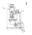
- FIG. 2 shows a hydraulic plan of the control arrangement 1 according to the invention in "holding the screed".
- the screed 41 is held in a raised position, for example for a transport movement.
- none of the directional control valves 11 to 16 is switched, so that they are not energized.
- Spring-loaded check valves 21 to 24 prevent a connection in the shown mode.
- all valves are designed as seat valves, so that no leakage can occur.
- the pressures that rest on the piston side and piston rod side are held, so that no sinking of the screed 41 can take place.
- a further actuating cylinder 3 can preferably be connected in parallel.
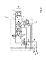
- FIG. 3 shows a hydraulic plan of the control arrangement 1 according to the invention in "lifting the screed".
- the directional control valves 11, 12, 13 connected, also recognizable by the "lightning symbols” in addition to the valve actuation elements, so that they are energized.
- the supply pressure which is preferably constant at 150 bar, wherein other supply pressures are possible depending on the cylinder dimensions and screed weight, is taken over the supply connection 5 for the control arrangement according to the invention.
- the control arrangement 1 according to the invention forms one of many units of the road paver, which have different functions.
- a supply unit (not shown) provides the constant supply pressure, so that various consumers in the sense of a "socket" can connect to it.
- valves 11, 12 is the throttled operating pressure piston rod side in the actuating cylinder 2.
- the hydraulic oil is pushed out of the piston side and via port 7 and the valves 13, 11, 21 supplied to the tank connection 6.
- the piston 2b is moved upward in the direction of the arrow 34 so that the screed 41 attached to the piston rod 2c is lifted.
- the valve 12 is switched in a time-delayed manner in order to prevent a slight sagging of the screed 41 at the beginning of the lifting operation. The reverse applies accordingly when stopping.
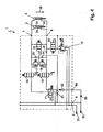
- FIG. 4 shows a hydraulic plan of the control arrangement 1 according to the invention in "lowering the screed".
- Pavers for road pavers can weigh up to several tons. Therefore, the weight of the screed 41 is used during lowering and the valve 11 is brought into the initial position shown.
- the piston rod-side displaced oil when lowering the screed is throttled over a shutter 25 to determine the lowering speed.
- Valves 12, 13 are energized and the piston rod side displaced hydraulic oil is supplied via valve 11 again the piston side of the actuating cylinder 2.
- the still missing difference is refilled via the check valve 22 from the biased tank port 6a, so that no cavitation occurs.
- the piston rod 2 c moves together with screed 41 in the direction of arrow 35 shown.
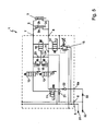
- FIG. 5 shows a hydraulic plan of the control arrangement 1 according to the invention during "swimming" of the screed 41.
- the screed 41 lies with its entire weight on the freshly built mix. Only valves 12, 13 are switched. Piston side and piston rod side of the actuating cylinder 2, 3 are again in communication. Supply connection 5 and tank connection 6 are mainly without function. It is only the difference in unevenness, etc. offset over the check valves 21, 22.
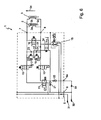
- FIG. 6 shows a hydraulic plan of the control arrangement 1 according to the invention in "controlling the screed load".
- a regulated pressure via pressure control valve 15, for example, a proportional valve which can regulate the pressure in a wide range, for example, 7 to 105 bar, and via valve 14 to the piston rod sides of the actuating cylinder 2, 3 passed .
- the adjustable pressure range of the proportional valve 15 begins near 0.
- the relief of the screed 41 leads inter alia to increase the rear axle load of the paver 40, so that a better traction is achieved.
- Secondary pressure relief valves 17, 18 ensure safety in the event of an increased external pressure system pressure.
- the pressure regulated by valve 15 is increased to compensate for the force generated by the buoyancy during installation so that the screed 41 does not sink onto the hot mix.
- the relief pressure can be regulated in proportion to the travel speed of the road paver 40.
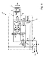
- FIG. 7 shows a hydraulic plan of the control arrangement 1 according to the invention in "controlling the screed load and additional unloading".
- this function can be activated by spring-loaded push button (not shown).
- the plank 41 is relieved by increased pressure, adjustable at the valve 15, to the piston rod sides of the actuating cylinder 2, 3, ie moved in the direction of arrow 34, so as to realize higher tensile force transmission.
- FIG. 8 shows a hydraulic plan of the control arrangement 1 according to the invention in "controlling the screed load and additional pressing".
- the control arrangement according to the invention described acts in parallel on both hydraulic cylinders 2 and 3. This is sufficient for the majority of applications, especially in the small pavers. Be heavy machines, especially with Bohleverbreiterept, it may be useful to separately provide the control arrangement according to the invention for each hydraulic cylinder 2, 3, so that each cylinder 2, 3 is controlled separately.
- the screed 41 is not widened symmetrically and thus the center of gravity of the screed 41 is no longer exactly between the two hydraulic cylinders 2, 3, it is advantageous instead of a parallel control of the cylinders 2, 3 via a control arrangement according to the invention for each cylinder 2, 3 to provide a separate control arrangement.
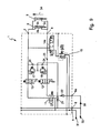
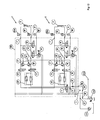
- FIG. 9 shows an alternative embodiment of the control arrangement according to the invention. It is different from the one in FIGS. 1 to 8 shown first embodiment in that the valves 14 and 16 of the first embodiment have been replaced by a 3/3-way valve 14a.
- the Bohle 41 can be loaded or unloaded according to the current driving condition.
- the advantages over the first embodiment are on the one hand in the reduction the number of components and the other in the simplification of the switching operations, for example, for "pressing" the screed 41, ie additional exercise of defined load pressure, instead of two switching operations, namely switching valves 14 and 16, only one switching operation for valve 14a is needed.
- the operating mode "control and unloading" is present. In this case, as required, a regulated relief pressure on the Kolbestangeneat the hydraulic cylinders 2, 3 will be given, so that the screed 41 can move in the direction of arrow 34.
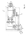
- FIG. 10 shows a further embodiment of the control arrangement according to the invention.
- the 2/2-way valves 14, 16 are no longer at least partially "in series" but arranged in parallel, the output of the valve 14 to the piston rod sides and the output of the valve 16 to the piston sides of the hydraulic cylinders 2, 3 are connected. It can also be with this embodiment optionally, according to the current driving condition, the Bohle 41 load or relieve.
- the pressure regulated by the pressure regulating valve 15 is applied to the piston sides of the hydraulic cylinders 2, 3 by actuation of the valve 16, so that the screed experiences an additional force in the direction of the arrow 35.
- FIG. 11 shows a first embodiment of a control system 100 with two control arrangements 1, 1 'according to the invention. They are connected in parallel in such a way that they have as common components only the directional control valve 11, the check valves 21, 22 and the terminals 5, 6 and 6a.
- the second control arrangement 1 'otherwise represents a doubling of the first control arrangement 1 with the same components.
- the two control arrangements 1, 1' have inter alia separately operable pressure control valves 15, 15 'and actuating cylinders 2, 3.
- the separately controlled pressures are indicated in each case via the pressure gauges 60, 60 '.
- the pressure sensors 50, 50 ' detect the respective pressures on the piston side of the hydraulic cylinders 2, 3. These pressures are ideal as parameters for controlling the screed load. Thanks to the double current regulator 40, 40 ', each with two current regulators 40a, 40b, a uniform lifting and lowering of the screed 41 is possible even if the screed 41 is extended on one side.
- FIG. 12 shows a further embodiment of the control system 100 according to the invention.
- the control system 100 has the possibility of additional pressing of the screed 41 with the aid of additional load pressures, the can be introduced via the valves 16, 16 'on the piston sides of the cylinder 2, 3 (comparable to Fig. 10 ).
- This pressing function is not required for most embodiments, as long as the overall center of gravity of the screed 41 between the articulation points of the two cylinders 2, 3 is located. However, if the center of gravity lies outside due to the design, then additional pressure can be used to ensure even and even load distribution.
- a control pump 101 is shown, which ensures a regulated volume flow or pressure.
- the flow or the pressure can be regulated according to demand. This leads to a low-loss and efficient operation of the hydraulic control arrangement 1 and the control system 100. With the aid of the control valve 102, the volume flow of the hydraulic oil flowing through the point 103 can be regulated.
- the control valve 102 may also be designed to control the pressure. As in Fig. 12 shown, at the point or node 103, a return line of another consumer (not shown) may be connected.
- FIG. 13 schematically shows a view of the screed 41 with uneven weight distribution.
- the screed 41 comprises a main screed 1001 and two screed spacers 1002 and 1003, which are hydraulically extendable individually via the traversing cylinders 1008 or 1009.
- additional additional planks 1004 to 1007 can be screwed to the spreader extensions 1002, 1003 to widen the working width.
- the actuating cylinders 2 and 3 designed as double-acting hydraulic cylinders are articulated on one side of a base beam 1001 at the same distance from the axis of symmetry 1015. With symmetrical widening of the screed 41, the overall center of gravity of the screed 41 lies on the symmetry line 1015.
- the cylinders 2 and 3 would preferably be supplied with the same loading and unloading pressure.
- FIG. 13 there are installation situations in which an asymmetrical broadening of the screed 41 is advantageous, as in FIG. 13 is shown.
- the center of gravity 1010 of the screed 41 shifts to the right by a length 1012, so that the line of action of the weight force 1011 of the screed 41 is also shifted by the length 1012 from the axis of symmetry 1015.
- Wegmessvorlegicardien 1013, 1014 are provided according to the invention, which are each arranged on one of the Verfahrzylinder 1008, 1009 and specify exactly what amount the piston rods of the Verfahrzylinder 1008, 1009 are extended. From the measured values, the displacement 1012 of the center of gravity 1010 can be determined exactly.
- the actuating cylinders 2, 3 with uneven weight distribution due to asymmetric Bohlenverbreiterung independent operated from each other, so that an overall uniform, even distribution and compression of the material is achieved.
- the right cylinder 2 could slightly raise the right side of the ground pile 1001 to counteract inclination due to the displacement 1012 of the center of gravity 1011. It is also conceivable to press the left side of the base pile 1001 over the left cylinder 3 on the material to be laid. It is of course also possible to carry out both measures simultaneously.
Landscapes
- Engineering & Computer Science (AREA)
- Architecture (AREA)
- Civil Engineering (AREA)
- Structural Engineering (AREA)
- Road Paving Machines (AREA)
- Fluid-Pressure Circuits (AREA)
Applications Claiming Priority (2)
| Application Number | Priority Date | Filing Date | Title |
|---|---|---|---|
| DE102009012384 | 2009-03-09 | ||
| DE102009019839A DE102009019839A1 (de) | 2009-03-09 | 2009-05-04 | Hydraulische Steueranordnung für die Bohle eines Straßenfertigers |
Publications (4)
| Publication Number | Publication Date |
|---|---|
| EP2233641A2 true EP2233641A2 (fr) | 2010-09-29 |
| EP2233641A3 EP2233641A3 (fr) | 2012-03-28 |
| EP2233641B1 EP2233641B1 (fr) | 2013-07-10 |
| EP2233641B2 EP2233641B2 (fr) | 2017-03-01 |
Family
ID=42558034
Family Applications (1)
| Application Number | Title | Priority Date | Filing Date |
|---|---|---|---|
| EP10002445.4A Active EP2233641B2 (fr) | 2009-03-09 | 2010-03-09 | Agencement de commande hydraulique pour la poutre lisseuse d'une finisseuse de route |
Country Status (4)
| Country | Link |
|---|---|
| US (1) | US9267248B2 (fr) |
| EP (1) | EP2233641B2 (fr) |
| CN (1) | CN101831860B (fr) |
| DE (1) | DE102009019839A1 (fr) |
Cited By (3)
| Publication number | Priority date | Publication date | Assignee | Title |
|---|---|---|---|---|
| EP2813619A1 (fr) * | 2013-06-11 | 2014-12-17 | Joseph Vögele AG | Poutre lisseuse pour une finisseuse de routes |
| DE102017002225A1 (de) | 2016-03-18 | 2017-09-21 | Bomag Gmbh | Straßenfertiger mit Steuereinheit zur Bestimmung des Gewichts und/oder der Schwerpunktlage und/oder der Breite der Bohle und Verfahren |
| CN107366648A (zh) * | 2017-09-11 | 2017-11-21 | 徐工集团工程机械股份有限公司 | 一种摊铺机熨平板的液压控制系统 |
Families Citing this family (12)
| Publication number | Priority date | Publication date | Assignee | Title |
|---|---|---|---|---|
| CN102071631B (zh) * | 2010-12-03 | 2012-02-01 | 成都市新筑路桥机械股份有限公司 | 摊铺机刮板卡料自动处理控制系统及控制方法 |
| US8979425B2 (en) | 2012-10-30 | 2015-03-17 | Caterpillar Paving Products Inc. | Screed extender speed control |
| DE102015006250C5 (de) * | 2014-05-20 | 2024-11-14 | Bomag Gmbh | Anbaubohleneinheit für einen Straßenfertiger und Straßenfertiger mit einer solchen Anbaubohleneinheit |
| US9388537B2 (en) * | 2014-06-09 | 2016-07-12 | Wirtgen Gmbh | Swing over steering |
| DE102016008253A1 (de) * | 2016-07-08 | 2018-01-11 | Dynapac Gmbh | Straßenfertiger und Verfahren zur Herstellung eines Straßenbelags |
| US10422086B2 (en) | 2017-11-13 | 2019-09-24 | Caterpillar Paving Products Inc. | Screed control system |
| CN109869377A (zh) * | 2017-12-01 | 2019-06-11 | 中国飞机强度研究所 | 一种可控卸载系统 |
| WO2019134744A1 (fr) * | 2018-01-03 | 2019-07-11 | Volvo Construction Equipment Ab | Machine de pavage et procédé d'étalonnage de hauteur de table lisseuse de pavage |
| US10156049B1 (en) * | 2018-08-27 | 2018-12-18 | Stuart Anthony Frost | Modular screed plate assembly and method of assembling a screed plate |
| CN117043428A (zh) * | 2021-02-23 | 2023-11-10 | 阿克塞诺克斯有限责任公司 | 用于整平板装置的压力传感器 |
| WO2022182675A1 (fr) | 2021-02-23 | 2022-09-01 | Axenox, Llc. | Capteur de pression pour appareil de plaque lisseuse |
| CN116641928A (zh) * | 2023-06-07 | 2023-08-25 | 江苏集萃道路工程技术与装备研究所有限公司 | 一种挡板浮动液压系统及其控制方法 |
Family Cites Families (41)
| Publication number | Priority date | Publication date | Assignee | Title |
|---|---|---|---|---|
| US2295519A (en) * | 1940-08-04 | 1942-09-08 | Jaeger Machine Co | Apparatus for surfacing roads |
| US2775925A (en) * | 1952-05-27 | 1957-01-01 | Buffalo Springfield Roller Co | Pressure control means for road rollers |
| CH372331A (de) * | 1959-07-13 | 1963-10-15 | Hermann Heise Carl | Strassendeckenfertiger für bituminöse Strassenbaustoffe |
| US3396642A (en) * | 1967-03-16 | 1968-08-13 | Koehring Co | Subgrading machine |
| US3606827A (en) † | 1968-11-07 | 1971-09-21 | Miller Formless Co Inc | Concrete curb laying machine |
| US3776326A (en) | 1969-12-31 | 1973-12-04 | Blaw Knox Const Equipment | Paving machine |
| US4026658A (en) * | 1974-07-26 | 1977-05-31 | Barber-Greene Company | Automatic support system for a screed |
| CA1014783A (en) * | 1974-10-12 | 1977-08-02 | Ernst-August Schrader | Device for the adjustment of the working width of road finishers |
| US3936211A (en) * | 1975-04-14 | 1976-02-03 | Miller Formless Co., Inc. | Drainage ditch mule |
| DE3124363A1 (de) * | 1981-06-20 | 1982-12-30 | Maschinenfabrik Klaus-Gerd Hoes GmbH & Co. KG, 2906 Wardenburg | Verfahren und vorrichtung zur korrektur des anstellwinkels von breitenverstellbaren strassenfertigerbohlen |
| DE8300083U1 (de) | 1983-01-04 | 1983-09-22 | Abg-Werke Gmbh, 3250 Hameln | Einbaubohle fuer einen strassenfertiger |
| EP0115561A1 (fr) | 1983-02-04 | 1984-08-15 | Firma Lispa, R. Lichtenstein | Couvercle pour récipient de cuisson |
| IT1176643B (it) * | 1984-09-04 | 1987-08-18 | Simesa Spa | Dispositivo per controllare la pressione esercitata dal gruppo livellatore vibrante di una macchina vibrofinitrice per pavimentazioni stradali |
| US4655633A (en) * | 1985-09-23 | 1987-04-07 | David W. Somero | Screeding apparatus and method |
| DE3535362C1 (de) * | 1985-10-03 | 1987-03-26 | Joseph Voegele Ag | Verfahren und Vorrichtung zur Hoehenregulierung einer Nivellierungsbohle |
| EP0244976A1 (fr) * | 1986-04-21 | 1987-11-11 | Vickers Systems Limited | Capteur de débit |
| DE3825129A1 (de) * | 1988-07-23 | 1990-01-25 | Ruthmann Anton Gmbh & Co | Hydrauliksteuerung fuer den schwenkarm einer hubarbeitsbuehne |
| US4930935A (en) * | 1988-12-29 | 1990-06-05 | David W. Somero | Screeding apparatus and method |
| JPH0712403Y2 (ja) † | 1989-03-29 | 1995-03-22 | 株式会社新潟鐵工所 | 敷き均し機械 |
| FR2666104B1 (fr) * | 1990-08-27 | 1993-04-09 | Cochery Bourdin Chausse | Procede et dispositif d'etalement d'une couche d'enrobe sur une chaussee et finisseur equipe d'un tel dispositif. |
| JPH0768684B2 (ja) † | 1990-11-14 | 1995-07-26 | 株式会社新潟鐵工所 | 敷均し機械 |
| DE69126017T2 (de) † | 1990-11-14 | 1997-11-06 | Niigata Engineering Co Ltd | Vorrichtung zur Regelung der Fahrbahnbelagsdicke |
| DE4211286C2 (de) | 1992-04-03 | 2003-08-21 | Metso Dynapac Gmbh | Verfahren zum Arretieren einer Einbausohle eines Straßenfertigers und Straßenfertiger zur Durchführung des Verfahrens |
| JPH0768684A (ja) | 1993-09-01 | 1995-03-14 | Plus Teku Kk | 防音用発泡シートとその製造法及び木質系複合床材 |
| JP2522906B2 (ja) | 1994-04-19 | 1996-08-07 | リンナイ株式会社 | 強制給気式二缶型湯沸器 |
| DE9406683U1 (de) * | 1994-04-21 | 1994-06-30 | Joseph Vögele AG, 68163 Mannheim | Straßenfertiger |
| JPH10266274A (ja) | 1997-03-27 | 1998-10-06 | Hitachi Constr Mach Co Ltd | 建設機械の油圧回路装置 |
| US6183160B1 (en) * | 1998-03-31 | 2001-02-06 | Delaware Capital Formation, Inc. | Screeding apparatus and method incorporating oscillating attachment |
| WO2000036231A1 (fr) | 1998-12-18 | 2000-06-22 | Caterpillar Inc. | Procede et appareil servant a commander un instrument de travail |
| US6749364B1 (en) * | 1999-05-19 | 2004-06-15 | Blaw-Knox Construction Equipment Corporation | Temperature sensing for controlling paving and compaction operations |
| JP3569172B2 (ja) * | 1999-08-24 | 2004-09-22 | 株式会社神戸製鋼所 | タイヤ加硫プレス用油圧システム |
| AU2001270281A1 (en) | 2000-07-05 | 2002-01-30 | The Raymond Company | Regeneration circuit |
| JP3846776B2 (ja) | 2001-02-06 | 2006-11-15 | 新キャタピラー三菱株式会社 | 作業機械におけるブームシリンダの油圧制御回路 |
| JP2002285513A (ja) | 2001-03-22 | 2002-10-03 | Shin Caterpillar Mitsubishi Ltd | 舗装機械におけるスクリードアシスト装置 |
| DE10155507B4 (de) | 2001-11-13 | 2005-10-06 | Abg Allgemeine Baumaschinen-Gesellschaft Mbh | Fertiger zum bodenseitigen Einbau von Schichten für Straßen od. dgl. |
| DE10311156B3 (de) | 2003-03-14 | 2004-12-02 | Sauer-Danfoss Aps | Fahrzeug mit einer Anbaueinrichtung |
| WO2006014909A2 (fr) * | 2004-07-26 | 2006-02-09 | Somero Enterprises, Inc. | Dispositif a araser motorise |
| JP2006161290A (ja) * | 2004-12-02 | 2006-06-22 | Sumitomo (Shi) Construction Machinery Manufacturing Co Ltd | 舗装機械のスクリード保持機構 |
| JP4006435B2 (ja) | 2004-12-07 | 2007-11-14 | 住友建機製造株式会社 | 道路舗設機におけるスクリード用リフトシリンダの背圧可変機構 |
| US7204185B2 (en) * | 2005-04-29 | 2007-04-17 | Caterpillar Inc | Hydraulic system having a pressure compensator |
| DE102005022266A1 (de) | 2005-05-10 | 2006-11-16 | Abg Allgemeine Baumaschinen-Gesellschaft Mbh | Fertiger zum bodenseitigen Einbau von Schichten für Straßen oder dgl. |
-
2009
- 2009-05-04 DE DE102009019839A patent/DE102009019839A1/de not_active Withdrawn
-
2010
- 2010-03-09 CN CN2010101299826A patent/CN101831860B/zh not_active Expired - Fee Related
- 2010-03-09 EP EP10002445.4A patent/EP2233641B2/fr active Active
- 2010-03-09 US US12/720,580 patent/US9267248B2/en active Active
Non-Patent Citations (1)
| Title |
|---|
| None |
Cited By (8)
| Publication number | Priority date | Publication date | Assignee | Title |
|---|---|---|---|---|
| EP2813619A1 (fr) * | 2013-06-11 | 2014-12-17 | Joseph Vögele AG | Poutre lisseuse pour une finisseuse de routes |
| US9447552B2 (en) | 2013-06-11 | 2016-09-20 | Joseph Voegele Ag | Paving screed for a road finisher |
| US9670629B2 (en) | 2013-06-11 | 2017-06-06 | Joseph Voegele Ag | Paving screed for a road finisher |
| EP3361003A1 (fr) * | 2013-06-11 | 2018-08-15 | Joseph Vögele AG | Finisseuse de routes avec une poutre lisseuse |
| DE102017002225A1 (de) | 2016-03-18 | 2017-09-21 | Bomag Gmbh | Straßenfertiger mit Steuereinheit zur Bestimmung des Gewichts und/oder der Schwerpunktlage und/oder der Breite der Bohle und Verfahren |
| US10260205B2 (en) | 2016-03-18 | 2019-04-16 | Bomag Gmbh | Road paver with control unit for determining the weight and/or the center of gravity and/or the width of the screed and corresponding method |
| CN107366648A (zh) * | 2017-09-11 | 2017-11-21 | 徐工集团工程机械股份有限公司 | 一种摊铺机熨平板的液压控制系统 |
| CN107366648B (zh) * | 2017-09-11 | 2023-08-29 | 徐工集团工程机械股份有限公司 | 一种摊铺机熨平板的液压控制系统 |
Also Published As
| Publication number | Publication date |
|---|---|
| CN101831860A (zh) | 2010-09-15 |
| US9267248B2 (en) | 2016-02-23 |
| CN101831860B (zh) | 2013-08-28 |
| EP2233641B2 (fr) | 2017-03-01 |
| EP2233641B1 (fr) | 2013-07-10 |
| US20100284742A1 (en) | 2010-11-11 |
| EP2233641A3 (fr) | 2012-03-28 |
| DE102009019839A1 (de) | 2010-09-16 |
Similar Documents
| Publication | Publication Date | Title |
|---|---|---|
| EP2233641B1 (fr) | Agencement de commande hydraulique pour la poutre lisseuse d'une finisseuse de route | |
| EP2325390B1 (fr) | Poutre lisseuse et finisseuse de route | |
| EP2230160B1 (fr) | Engin de construction de chaussées, chaîne d'un tel engin et procédé de mise sous tension de la chaîne | |
| EP2171285B1 (fr) | Dispositif de commande hydraulique | |
| EP2225470B1 (fr) | Système de distributeur | |
| EP2043422A1 (fr) | Installation hydraulique | |
| DE112017003054B4 (de) | Hydraulisches ansteuersystem | |
| DE102013020901A1 (de) | Selbstfahrende Baumaschine | |
| DE102008049409A1 (de) | Asphaltiermaschine mit einem einstellbaren Ballastsystem und Verfahren dafür | |
| DE4318945A1 (de) | Hydraulikkreis für ein Vier-Wege-Selektorventil mit geschlossener Mittenstellung | |
| DE3914904C2 (de) | Regelung für eine lastabhängig arbeitende Verstellpumpe | |
| EP3498913B1 (fr) | Finisseuse de route pourvue d'un châssis pouvant être relevé | |
| EP0902126B1 (fr) | Finisseur | |
| DE69414614T2 (de) | Stromventil mit Vorsteuerung und Druckkompensation | |
| DE3710699C1 (de) | Hydraulische Steuervorrichtung fuer eine Verbrauchergruppe | |
| EP3498915B1 (fr) | Finisseuse de route pourvue de châssis pouvant être relevé | |
| EP2404493B1 (fr) | Dispositif de levage | |
| EP2142808A1 (fr) | Ensemble de commande hydraulique | |
| CH700344B1 (de) | Steuervorrichtung für mindestens zwei hydraulische Antriebe. | |
| DE4209472A1 (de) | Schaltungsanordnung zur geschwindigkeitssteuerung von hydraulischen antrieben, vorzugsweise hydraulischen arbeitszylindern | |
| EP2016818B1 (fr) | Dispositif de levage et procédé de commande d'un tel dispositif de levage | |
| DE4226936C1 (de) | Flurförderzeug, insbesondere fahrerloses Fahrzeug | |
| DE3346000C2 (fr) | ||
| DE102007034746B4 (de) | Hydrostatisches Antriebssystem | |
| DE19541190A1 (de) | Hydraulische Anordnung zur Steuerung des Hubwerks einer mobilen Arbeitsmaschine |
Legal Events
| Date | Code | Title | Description |
|---|---|---|---|
| PUAI | Public reference made under article 153(3) epc to a published international application that has entered the european phase |
Free format text: ORIGINAL CODE: 0009012 |
|
| AK | Designated contracting states |
Kind code of ref document: A2 Designated state(s): AT BE BG CH CY CZ DE DK EE ES FI FR GB GR HR HU IE IS IT LI LT LU LV MC MK MT NL NO PL PT RO SE SI SK SM TR |
|
| AX | Request for extension of the european patent |
Extension state: AL BA ME RS |
|
| PUAL | Search report despatched |
Free format text: ORIGINAL CODE: 0009013 |
|
| RIC1 | Information provided on ipc code assigned before grant |
Ipc: E01C 19/48 20060101AFI20120216BHEP |
|
| AK | Designated contracting states |
Kind code of ref document: A3 Designated state(s): AT BE BG CH CY CZ DE DK EE ES FI FR GB GR HR HU IE IS IT LI LT LU LV MC MK MT NL NO PL PT RO SE SI SK SM TR |
|
| AX | Request for extension of the european patent |
Extension state: AL BA ME RS |
|
| 17P | Request for examination filed |
Effective date: 20120504 |
|
| GRAP | Despatch of communication of intention to grant a patent |
Free format text: ORIGINAL CODE: EPIDOSNIGR1 |
|
| GRAS | Grant fee paid |
Free format text: ORIGINAL CODE: EPIDOSNIGR3 |
|
| GRAA | (expected) grant |
Free format text: ORIGINAL CODE: 0009210 |
|
| AK | Designated contracting states |
Kind code of ref document: B1 Designated state(s): AT BE BG CH CY CZ DE DK EE ES FI FR GB GR HR HU IE IS IT LI LT LU LV MC MK MT NL NO PL PT RO SE SI SK SM TR |
|
| REG | Reference to a national code |
Ref country code: GB Ref legal event code: FG4D Free format text: NOT ENGLISH |
|
| REG | Reference to a national code |
Ref country code: AT Ref legal event code: REF Ref document number: 621059 Country of ref document: AT Kind code of ref document: T Effective date: 20130715 Ref country code: CH Ref legal event code: EP |
|
| REG | Reference to a national code |
Ref country code: IE Ref legal event code: FG4D Free format text: LANGUAGE OF EP DOCUMENT: GERMAN |
|
| REG | Reference to a national code |
Ref country code: DE Ref legal event code: R096 Ref document number: 502010003925 Country of ref document: DE Effective date: 20130905 |
|
| PG25 | Lapsed in a contracting state [announced via postgrant information from national office to epo] |
Ref country code: SI Free format text: LAPSE BECAUSE OF FAILURE TO SUBMIT A TRANSLATION OF THE DESCRIPTION OR TO PAY THE FEE WITHIN THE PRESCRIBED TIME-LIMIT Effective date: 20130710 |
|
| REG | Reference to a national code |
Ref country code: NL Ref legal event code: VDEP Effective date: 20130710 |
|
| REG | Reference to a national code |
Ref country code: LT Ref legal event code: MG4D |
|
| PG25 | Lapsed in a contracting state [announced via postgrant information from national office to epo] |
Ref country code: SE Free format text: LAPSE BECAUSE OF FAILURE TO SUBMIT A TRANSLATION OF THE DESCRIPTION OR TO PAY THE FEE WITHIN THE PRESCRIBED TIME-LIMIT Effective date: 20130710 Ref country code: CY Free format text: LAPSE BECAUSE OF FAILURE TO SUBMIT A TRANSLATION OF THE DESCRIPTION OR TO PAY THE FEE WITHIN THE PRESCRIBED TIME-LIMIT Effective date: 20130904 Ref country code: PT Free format text: LAPSE BECAUSE OF FAILURE TO SUBMIT A TRANSLATION OF THE DESCRIPTION OR TO PAY THE FEE WITHIN THE PRESCRIBED TIME-LIMIT Effective date: 20131111 Ref country code: HR Free format text: LAPSE BECAUSE OF FAILURE TO SUBMIT A TRANSLATION OF THE DESCRIPTION OR TO PAY THE FEE WITHIN THE PRESCRIBED TIME-LIMIT Effective date: 20130710 Ref country code: IS Free format text: LAPSE BECAUSE OF FAILURE TO SUBMIT A TRANSLATION OF THE DESCRIPTION OR TO PAY THE FEE WITHIN THE PRESCRIBED TIME-LIMIT Effective date: 20131110 Ref country code: LT Free format text: LAPSE BECAUSE OF FAILURE TO SUBMIT A TRANSLATION OF THE DESCRIPTION OR TO PAY THE FEE WITHIN THE PRESCRIBED TIME-LIMIT Effective date: 20130710 Ref country code: NO Free format text: LAPSE BECAUSE OF FAILURE TO SUBMIT A TRANSLATION OF THE DESCRIPTION OR TO PAY THE FEE WITHIN THE PRESCRIBED TIME-LIMIT Effective date: 20131010 |
|
| PG25 | Lapsed in a contracting state [announced via postgrant information from national office to epo] |
Ref country code: NL Free format text: LAPSE BECAUSE OF FAILURE TO SUBMIT A TRANSLATION OF THE DESCRIPTION OR TO PAY THE FEE WITHIN THE PRESCRIBED TIME-LIMIT Effective date: 20130710 Ref country code: GR Free format text: LAPSE BECAUSE OF FAILURE TO SUBMIT A TRANSLATION OF THE DESCRIPTION OR TO PAY THE FEE WITHIN THE PRESCRIBED TIME-LIMIT Effective date: 20131011 Ref country code: FI Free format text: LAPSE BECAUSE OF FAILURE TO SUBMIT A TRANSLATION OF THE DESCRIPTION OR TO PAY THE FEE WITHIN THE PRESCRIBED TIME-LIMIT Effective date: 20130710 Ref country code: ES Free format text: LAPSE BECAUSE OF FAILURE TO SUBMIT A TRANSLATION OF THE DESCRIPTION OR TO PAY THE FEE WITHIN THE PRESCRIBED TIME-LIMIT Effective date: 20131021 Ref country code: PL Free format text: LAPSE BECAUSE OF FAILURE TO SUBMIT A TRANSLATION OF THE DESCRIPTION OR TO PAY THE FEE WITHIN THE PRESCRIBED TIME-LIMIT Effective date: 20130710 Ref country code: LV Free format text: LAPSE BECAUSE OF FAILURE TO SUBMIT A TRANSLATION OF THE DESCRIPTION OR TO PAY THE FEE WITHIN THE PRESCRIBED TIME-LIMIT Effective date: 20130710 |
|
| PG25 | Lapsed in a contracting state [announced via postgrant information from national office to epo] |
Ref country code: CY Free format text: LAPSE BECAUSE OF FAILURE TO SUBMIT A TRANSLATION OF THE DESCRIPTION OR TO PAY THE FEE WITHIN THE PRESCRIBED TIME-LIMIT Effective date: 20130710 |
|
| PLBI | Opposition filed |
Free format text: ORIGINAL CODE: 0009260 |
|
| PLBI | Opposition filed |
Free format text: ORIGINAL CODE: 0009260 |
|
| PG25 | Lapsed in a contracting state [announced via postgrant information from national office to epo] |
Ref country code: SK Free format text: LAPSE BECAUSE OF FAILURE TO SUBMIT A TRANSLATION OF THE DESCRIPTION OR TO PAY THE FEE WITHIN THE PRESCRIBED TIME-LIMIT Effective date: 20130710 Ref country code: RO Free format text: LAPSE BECAUSE OF FAILURE TO SUBMIT A TRANSLATION OF THE DESCRIPTION OR TO PAY THE FEE WITHIN THE PRESCRIBED TIME-LIMIT Effective date: 20130710 Ref country code: DK Free format text: LAPSE BECAUSE OF FAILURE TO SUBMIT A TRANSLATION OF THE DESCRIPTION OR TO PAY THE FEE WITHIN THE PRESCRIBED TIME-LIMIT Effective date: 20130710 Ref country code: CZ Free format text: LAPSE BECAUSE OF FAILURE TO SUBMIT A TRANSLATION OF THE DESCRIPTION OR TO PAY THE FEE WITHIN THE PRESCRIBED TIME-LIMIT Effective date: 20130710 Ref country code: EE Free format text: LAPSE BECAUSE OF FAILURE TO SUBMIT A TRANSLATION OF THE DESCRIPTION OR TO PAY THE FEE WITHIN THE PRESCRIBED TIME-LIMIT Effective date: 20130710 |
|
| 26 | Opposition filed |
Opponent name: ABG ALLGEMEINE BAUMASCHINEN-GESELLSCHAFT MBH Effective date: 20140404 |
|
| 26 | Opposition filed |
Opponent name: JOSEPH VOEGELE AG Effective date: 20140410 |
|
| PG25 | Lapsed in a contracting state [announced via postgrant information from national office to epo] |
Ref country code: IT Free format text: LAPSE BECAUSE OF FAILURE TO SUBMIT A TRANSLATION OF THE DESCRIPTION OR TO PAY THE FEE WITHIN THE PRESCRIBED TIME-LIMIT Effective date: 20130710 |
|
| REG | Reference to a national code |
Ref country code: DE Ref legal event code: R026 Ref document number: 502010003925 Country of ref document: DE Effective date: 20140404 |
|
| PLAX | Notice of opposition and request to file observation + time limit sent |
Free format text: ORIGINAL CODE: EPIDOSNOBS2 |
|
| PLAF | Information modified related to communication of a notice of opposition and request to file observations + time limit |
Free format text: ORIGINAL CODE: EPIDOSCOBS2 |
|
| PG25 | Lapsed in a contracting state [announced via postgrant information from national office to epo] |
Ref country code: LU Free format text: LAPSE BECAUSE OF FAILURE TO SUBMIT A TRANSLATION OF THE DESCRIPTION OR TO PAY THE FEE WITHIN THE PRESCRIBED TIME-LIMIT Effective date: 20140309 |
|
| REG | Reference to a national code |
Ref country code: CH Ref legal event code: PL |
|
| GBPC | Gb: european patent ceased through non-payment of renewal fee |
Effective date: 20140309 |
|
| REG | Reference to a national code |
Ref country code: FR Ref legal event code: ST Effective date: 20141128 |
|
| REG | Reference to a national code |
Ref country code: IE Ref legal event code: MM4A |
|
| PLBB | Reply of patent proprietor to notice(s) of opposition received |
Free format text: ORIGINAL CODE: EPIDOSNOBS3 |
|
| PG25 | Lapsed in a contracting state [announced via postgrant information from national office to epo] |
Ref country code: FR Free format text: LAPSE BECAUSE OF NON-PAYMENT OF DUE FEES Effective date: 20140331 Ref country code: CH Free format text: LAPSE BECAUSE OF NON-PAYMENT OF DUE FEES Effective date: 20140331 Ref country code: GB Free format text: LAPSE BECAUSE OF NON-PAYMENT OF DUE FEES Effective date: 20140309 Ref country code: LI Free format text: LAPSE BECAUSE OF NON-PAYMENT OF DUE FEES Effective date: 20140331 Ref country code: IE Free format text: LAPSE BECAUSE OF NON-PAYMENT OF DUE FEES Effective date: 20140309 |
|
| PLAB | Opposition data, opponent's data or that of the opponent's representative modified |
Free format text: ORIGINAL CODE: 0009299OPPO |
|
| R26 | Opposition filed (corrected) |
Opponent name: JOSEPH VOEGELE AG Effective date: 20140410 |
|
| PG25 | Lapsed in a contracting state [announced via postgrant information from national office to epo] |
Ref country code: MT Free format text: LAPSE BECAUSE OF FAILURE TO SUBMIT A TRANSLATION OF THE DESCRIPTION OR TO PAY THE FEE WITHIN THE PRESCRIBED TIME-LIMIT Effective date: 20130710 |
|
| PG25 | Lapsed in a contracting state [announced via postgrant information from national office to epo] |
Ref country code: SM Free format text: LAPSE BECAUSE OF FAILURE TO SUBMIT A TRANSLATION OF THE DESCRIPTION OR TO PAY THE FEE WITHIN THE PRESCRIBED TIME-LIMIT Effective date: 20130710 |
|
| REG | Reference to a national code |
Ref country code: AT Ref legal event code: MM01 Ref document number: 621059 Country of ref document: AT Kind code of ref document: T Effective date: 20150309 |
|
| PG25 | Lapsed in a contracting state [announced via postgrant information from national office to epo] |
Ref country code: MC Free format text: LAPSE BECAUSE OF FAILURE TO SUBMIT A TRANSLATION OF THE DESCRIPTION OR TO PAY THE FEE WITHIN THE PRESCRIBED TIME-LIMIT Effective date: 20130710 |
|
| PG25 | Lapsed in a contracting state [announced via postgrant information from national office to epo] |
Ref country code: BG Free format text: LAPSE BECAUSE OF FAILURE TO SUBMIT A TRANSLATION OF THE DESCRIPTION OR TO PAY THE FEE WITHIN THE PRESCRIBED TIME-LIMIT Effective date: 20130710 |
|
| PG25 | Lapsed in a contracting state [announced via postgrant information from national office to epo] |
Ref country code: TR Free format text: LAPSE BECAUSE OF FAILURE TO SUBMIT A TRANSLATION OF THE DESCRIPTION OR TO PAY THE FEE WITHIN THE PRESCRIBED TIME-LIMIT Effective date: 20130710 Ref country code: BE Free format text: LAPSE BECAUSE OF FAILURE TO SUBMIT A TRANSLATION OF THE DESCRIPTION OR TO PAY THE FEE WITHIN THE PRESCRIBED TIME-LIMIT Effective date: 20140331 Ref country code: HU Free format text: LAPSE BECAUSE OF FAILURE TO SUBMIT A TRANSLATION OF THE DESCRIPTION OR TO PAY THE FEE WITHIN THE PRESCRIBED TIME-LIMIT; INVALID AB INITIO Effective date: 20100309 |
|
| PG25 | Lapsed in a contracting state [announced via postgrant information from national office to epo] |
Ref country code: AT Free format text: LAPSE BECAUSE OF NON-PAYMENT OF DUE FEES Effective date: 20150309 |
|
| PUAH | Patent maintained in amended form |
Free format text: ORIGINAL CODE: 0009272 |
|
| STAA | Information on the status of an ep patent application or granted ep patent |
Free format text: STATUS: PATENT MAINTAINED AS AMENDED |
|
| 27A | Patent maintained in amended form |
Effective date: 20170301 |
|
| AK | Designated contracting states |
Kind code of ref document: B2 Designated state(s): AT BE BG CH CY CZ DE DK EE ES FI FR GB GR HR HU IE IS IT LI LT LU LV MC MK MT NL NO PL PT RO SE SI SK SM TR |
|
| REG | Reference to a national code |
Ref country code: DE Ref legal event code: R102 Ref document number: 502010003925 Country of ref document: DE |
|
| PG25 | Lapsed in a contracting state [announced via postgrant information from national office to epo] |
Ref country code: MK Free format text: LAPSE BECAUSE OF FAILURE TO SUBMIT A TRANSLATION OF THE DESCRIPTION OR TO PAY THE FEE WITHIN THE PRESCRIBED TIME-LIMIT Effective date: 20130710 |
|
| P01 | Opt-out of the competence of the unified patent court (upc) registered |
Effective date: 20230527 |
|
| REG | Reference to a national code |
Ref country code: DE Ref legal event code: R082 Ref document number: 502010003925 Country of ref document: DE Representative=s name: ZIMMERMANN & PARTNER PATENTANWAELTE MBB, DE |
|
| PGFP | Annual fee paid to national office [announced via postgrant information from national office to epo] |
Ref country code: DE Payment date: 20250319 Year of fee payment: 16 |