EP2236716A2 - Porte coulissante et pivotante - Google Patents
Porte coulissante et pivotante Download PDFInfo
- Publication number
- EP2236716A2 EP2236716A2 EP10002542A EP10002542A EP2236716A2 EP 2236716 A2 EP2236716 A2 EP 2236716A2 EP 10002542 A EP10002542 A EP 10002542A EP 10002542 A EP10002542 A EP 10002542A EP 2236716 A2 EP2236716 A2 EP 2236716A2
- Authority
- EP
- European Patent Office
- Prior art keywords
- door
- door leaf
- sliding
- rotary column
- movement
- Prior art date
- Legal status (The legal status is an assumption and is not a legal conclusion. Google has not performed a legal analysis and makes no representation as to the accuracy of the status listed.)
- Withdrawn
Links
Images







Classifications
-
- E—FIXED CONSTRUCTIONS
- E05—LOCKS; KEYS; WINDOW OR DOOR FITTINGS; SAFES
- E05D—HINGES OR SUSPENSION DEVICES FOR DOORS, WINDOWS OR WINGS
- E05D15/00—Suspension arrangements for wings
- E05D15/56—Suspension arrangements for wings with successive different movements
- E05D15/58—Suspension arrangements for wings with successive different movements with both swinging and sliding movements
-
- E—FIXED CONSTRUCTIONS
- E05—LOCKS; KEYS; WINDOW OR DOOR FITTINGS; SAFES
- E05F—DEVICES FOR MOVING WINGS INTO OPEN OR CLOSED POSITION; CHECKS FOR WINGS; WING FITTINGS NOT OTHERWISE PROVIDED FOR, CONCERNED WITH THE FUNCTIONING OF THE WING
- E05F15/00—Power-operated mechanisms for wings
- E05F15/60—Power-operated mechanisms for wings using electrical actuators
- E05F15/603—Power-operated mechanisms for wings using electrical actuators using rotary electromotors
- E05F15/611—Power-operated mechanisms for wings using electrical actuators using rotary electromotors for swinging wings
- E05F15/614—Power-operated mechanisms for wings using electrical actuators using rotary electromotors for swinging wings operated by meshing gear wheels, one of which being mounted at the wing pivot axis; operated by a motor acting directly on the wing pivot axis
-
- E—FIXED CONSTRUCTIONS
- E05—LOCKS; KEYS; WINDOW OR DOOR FITTINGS; SAFES
- E05F—DEVICES FOR MOVING WINGS INTO OPEN OR CLOSED POSITION; CHECKS FOR WINGS; WING FITTINGS NOT OTHERWISE PROVIDED FOR, CONCERNED WITH THE FUNCTIONING OF THE WING
- E05F15/00—Power-operated mechanisms for wings
- E05F15/60—Power-operated mechanisms for wings using electrical actuators
- E05F15/603—Power-operated mechanisms for wings using electrical actuators using rotary electromotors
- E05F15/611—Power-operated mechanisms for wings using electrical actuators using rotary electromotors for swinging wings
- E05F15/63—Power-operated mechanisms for wings using electrical actuators using rotary electromotors for swinging wings operated by swinging arms
-
- E—FIXED CONSTRUCTIONS
- E05—LOCKS; KEYS; WINDOW OR DOOR FITTINGS; SAFES
- E05F—DEVICES FOR MOVING WINGS INTO OPEN OR CLOSED POSITION; CHECKS FOR WINGS; WING FITTINGS NOT OTHERWISE PROVIDED FOR, CONCERNED WITH THE FUNCTIONING OF THE WING
- E05F15/00—Power-operated mechanisms for wings
- E05F15/60—Power-operated mechanisms for wings using electrical actuators
- E05F15/603—Power-operated mechanisms for wings using electrical actuators using rotary electromotors
- E05F15/632—Power-operated mechanisms for wings using electrical actuators using rotary electromotors for horizontally-sliding wings
- E05F15/643—Power-operated mechanisms for wings using electrical actuators using rotary electromotors for horizontally-sliding wings operated by flexible elongated pulling elements, e.g. belts, chains or cables
-
- E—FIXED CONSTRUCTIONS
- E05—LOCKS; KEYS; WINDOW OR DOOR FITTINGS; SAFES
- E05F—DEVICES FOR MOVING WINGS INTO OPEN OR CLOSED POSITION; CHECKS FOR WINGS; WING FITTINGS NOT OTHERWISE PROVIDED FOR, CONCERNED WITH THE FUNCTIONING OF THE WING
- E05F15/00—Power-operated mechanisms for wings
- E05F15/60—Power-operated mechanisms for wings using electrical actuators
- E05F15/603—Power-operated mechanisms for wings using electrical actuators using rotary electromotors
- E05F15/632—Power-operated mechanisms for wings using electrical actuators using rotary electromotors for horizontally-sliding wings
- E05F15/652—Power-operated mechanisms for wings using electrical actuators using rotary electromotors for horizontally-sliding wings operated by screw-and-nut mechanisms
-
- E—FIXED CONSTRUCTIONS
- E05—LOCKS; KEYS; WINDOW OR DOOR FITTINGS; SAFES
- E05F—DEVICES FOR MOVING WINGS INTO OPEN OR CLOSED POSITION; CHECKS FOR WINGS; WING FITTINGS NOT OTHERWISE PROVIDED FOR, CONCERNED WITH THE FUNCTIONING OF THE WING
- E05F17/00—Special devices for shifting a plurality of wings operated simultaneously
-
- E—FIXED CONSTRUCTIONS
- E05—LOCKS; KEYS; WINDOW OR DOOR FITTINGS; SAFES
- E05D—HINGES OR SUSPENSION DEVICES FOR DOORS, WINDOWS OR WINGS
- E05D15/00—Suspension arrangements for wings
- E05D15/56—Suspension arrangements for wings with successive different movements
- E05D15/58—Suspension arrangements for wings with successive different movements with both swinging and sliding movements
- E05D2015/585—Suspension arrangements for wings with successive different movements with both swinging and sliding movements with stationary hinge parts
-
- E—FIXED CONSTRUCTIONS
- E05—LOCKS; KEYS; WINDOW OR DOOR FITTINGS; SAFES
- E05Y—INDEXING SCHEME ASSOCIATED WITH SUBCLASSES E05D AND E05F, RELATING TO CONSTRUCTION ELEMENTS, ELECTRIC CONTROL, POWER SUPPLY, POWER SIGNAL OR TRANSMISSION, USER INTERFACES, MOUNTING OR COUPLING, DETAILS, ACCESSORIES, AUXILIARY OPERATIONS NOT OTHERWISE PROVIDED FOR, APPLICATION THEREOF
- E05Y2201/00—Constructional elements; Accessories therefor
- E05Y2201/60—Suspension or transmission members; Accessories therefor
- E05Y2201/606—Accessories therefor
- E05Y2201/62—Synchronisation of suspension or transmission members
-
- E—FIXED CONSTRUCTIONS
- E05—LOCKS; KEYS; WINDOW OR DOOR FITTINGS; SAFES
- E05Y—INDEXING SCHEME ASSOCIATED WITH SUBCLASSES E05D AND E05F, RELATING TO CONSTRUCTION ELEMENTS, ELECTRIC CONTROL, POWER SUPPLY, POWER SIGNAL OR TRANSMISSION, USER INTERFACES, MOUNTING OR COUPLING, DETAILS, ACCESSORIES, AUXILIARY OPERATIONS NOT OTHERWISE PROVIDED FOR, APPLICATION THEREOF
- E05Y2800/00—Details, accessories and auxiliary operations not otherwise provided for
- E05Y2800/10—Additional functions
- E05Y2800/122—Telescopic action
-
- E—FIXED CONSTRUCTIONS
- E05—LOCKS; KEYS; WINDOW OR DOOR FITTINGS; SAFES
- E05Y—INDEXING SCHEME ASSOCIATED WITH SUBCLASSES E05D AND E05F, RELATING TO CONSTRUCTION ELEMENTS, ELECTRIC CONTROL, POWER SUPPLY, POWER SIGNAL OR TRANSMISSION, USER INTERFACES, MOUNTING OR COUPLING, DETAILS, ACCESSORIES, AUXILIARY OPERATIONS NOT OTHERWISE PROVIDED FOR, APPLICATION THEREOF
- E05Y2800/00—Details, accessories and auxiliary operations not otherwise provided for
- E05Y2800/26—Form or shape
- E05Y2800/262—Form or shape column shaped
-
- E—FIXED CONSTRUCTIONS
- E05—LOCKS; KEYS; WINDOW OR DOOR FITTINGS; SAFES
- E05Y—INDEXING SCHEME ASSOCIATED WITH SUBCLASSES E05D AND E05F, RELATING TO CONSTRUCTION ELEMENTS, ELECTRIC CONTROL, POWER SUPPLY, POWER SIGNAL OR TRANSMISSION, USER INTERFACES, MOUNTING OR COUPLING, DETAILS, ACCESSORIES, AUXILIARY OPERATIONS NOT OTHERWISE PROVIDED FOR, APPLICATION THEREOF
- E05Y2900/00—Application of doors, windows, wings or fittings thereof
-
- E—FIXED CONSTRUCTIONS
- E05—LOCKS; KEYS; WINDOW OR DOOR FITTINGS; SAFES
- E05Y—INDEXING SCHEME ASSOCIATED WITH SUBCLASSES E05D AND E05F, RELATING TO CONSTRUCTION ELEMENTS, ELECTRIC CONTROL, POWER SUPPLY, POWER SIGNAL OR TRANSMISSION, USER INTERFACES, MOUNTING OR COUPLING, DETAILS, ACCESSORIES, AUXILIARY OPERATIONS NOT OTHERWISE PROVIDED FOR, APPLICATION THEREOF
- E05Y2900/00—Application of doors, windows, wings or fittings thereof
- E05Y2900/10—Application of doors, windows, wings or fittings thereof for buildings or parts thereof
- E05Y2900/13—Type of wing
- E05Y2900/132—Doors
Definitions
- the present invention relates to a sliding hinged door having at least one door leaf assembly which is pivotally received about an associated pivot axis. Further, the present invention relates to a method for opening and closing operation of the sliding swing door.
- a sliding swing door with a door leaf assembly which is pivotally received about an associated pivot axis.
- upper and / or lower guide rails are necessary.
- the guide rails may be incorporated in the ceiling or floor of a room over which the door leaf assembly is both guided and held. This results in a kind of folding movement, by which a pivoting range of the door leaf assembly is achieved, which is smaller than the required pivoting range, which is determined by an exclusive pivotal movement of the door leaf assembly about a pivot axis.
- the door leaf assembly may include a plurality of door leaves, but which are known only in a left and right side arrangement to each other. In such sliding-swing doors fold the door wings with the movement described above, both to the left and to the right, so that the extension plane the door leaf is aligned approximately parallel to the loading direction of the sliding pivot door when it is open.
- the invention includes the technical teaching that the Matutelfan Aunt has a first door which is pivotable about a pivot axis, and at least one second door is provided which is linearly guided on the first door and pivotable with the first door around the pivot axis.
- the invention is based on the idea of combining a pivotally moving first door leaf with at least one further linearly and pivotally moving second door leaf.
- the second door is arranged linearly movable on the first door. If the first door leaf makes a movement about the pivot axis, it will settle Pivoting movement in the second door continued. However, the first door is only pivotally moved, wherein the second door can perform a pivotal movement superimposed linear movement, which runs along the first door leaf.
- the present invention starts from at least one second door leaf, so that in the context of the present invention any number of further door leaves can be arranged in each case and guided to one another.
- the sliding swing door can be designed as a double-leaf, wherein a left-wing door arrangement and a right-wing arrangement are provided, which each consist of two or more, individual door wings.
- the linear movement of the second door leaf along the first door can be designed in various ways.
- the first door can be made double-walled, wherein the two walls have a distance from each other, whereby a cavity is formed.
- the second door can be guided during the retraction movement into the cavity between the walls of the first door leaf.
- the walls can be made of any material, in particular of a glass material, a wood material or the like or have this.
- the second door can be guided parallel spaced on the first door along. This eliminates the double-walled design of the first door leaf, so that in the open state of the door leaf assembly two or more leaves are in a stacked arrangement next to each other.
- the door leaf arrangement is pivotable between a closed position and an open position, wherein the door leaves in the closed position substantially in front of each other and in the opening position are arranged substantially side by side. However, it also remains in the closed position an overlapping portion of the respective door leaf on top of each other, since the door must be held together.
- the sliding swing door may be provided with one or two door leaf assemblies, wherein a sliding swing door having two door leaf assemblies has a left-side and a right-side door leaf arrangement with respect to the walking direction, and the pivoting axes are respectively disposed outside.
- the maximum opening width of the sliding pivot door is consequently determined by the distance of the two pivot axes from each other.
- the space required for the movement of the door leaf assembly between the closed position and the open position can be approximately halved, with the space required for two door leaf assemblies with respect to the passage width of the sliding swing door can be reduced to about a quarter.
- a first electric drive unit for driving the door leaf arrangement can be integrated into the sliding pivot door.
- the respective first electric drive unit is arranged according to classical montages, i. H. Lintel and / or door leaf mounting on the hinge side or hinge opposite side to be mounted with respect to the first door leaf of the respective door leaf arrangement.
- first electric drive unit is inserted into the lintel or a similar stationary element and an associated slide rail is inserted into the door leaf, in each case not visible from the outside.
- This arrangement can also be reversed, so that the drive is inserted into the door leaf of the first door leaf.
- the first electric drive unit is preferably provided for carrying out the pivoting movement of the door leaves.
- the first electric drive unit in addition to the drive of the pivoting movement, furthermore drives the linear movement of the second door leaf along the first door leaf.
- this can have, for each door leaf arrangement, in each case one rotary column which is provided for receiving the respective door leaf arrangement.
- the first door leaf of the respective door leaf arrangement adjoins with its shunt edge to the rotary column, wherein the rotary column can rotate with the pivoting movement of the connected door leaves, or the rotary column is designed as a stationary rotary column, so that the door pivot around the stationary rotary column around.
- the rotary column can be designed in the form of a tube, so that at least the first electric drive unit can be accommodated in the rotary column.
- the first electric drive unit may comprise a first electric motor, which is accommodated in the rotary column and which is designed to drive the pivoting movement of the door leaf and pivot axis.
- the rotary column is rotatably received via a ceiling mount and / or floor bearings, wherein the first electric motor cooperates with a first gear unit and wherein the pivotal movement of the door by a mechanical operative connection between the first gear unit and the ceiling mount and / or the bottom bearing is generated.
- the unit of the first electric motor and the gear unit rotatably be included in the rotary column, wherein an output shaft rotatably connected to the ceiling mount and / or the bottom bearing.
- the first electric drive unit which is provided in particular for carrying out the pivoting movement of the door leaf arrangement, can be present several times in the sliding pivoting door and in particular in the rotary column.
- a first electric drive unit on the bottom side and another, identical electric drive unit may be present on the ceiling side, so that the respective output shaft is connected to both the bottom bearing and the ceiling mount.
- the rotary column may have a building-fixed portion in which the first electric motor and / or the first gear unit is rotatably received.
- the output shaft of the first electric drive unit acts on at least one remaining, rotatable part of the rotary column. This can be set in rotation by operation of the first electric drive unit.
- the first electric motor via the first gear unit may also be provided for driving the telescopic movement of the second door leaf along the first door leaf.
- a threaded spindle and / or a traction drive can be used, wherein the first electric motor drives the threaded spindle and / or the traction mechanism via the first gear unit.
- Both the threaded spindle and the Traction drive can only be integrated in the upper beam, only in the lower beam or in both bars of the first door leaf. Consequently, the first electric drive unit can be provided both simply on the upper side or on the lower side or both on the lower side and on the upper side within the rotary column.
- the sliding swing door may have a second electric drive unit.
- This can have at least one second electric motor and at least one second transmission unit connected thereto.
- the second electric motor or the second gear unit can also be accommodated in the rotary column and act to drive the telescopic movement of the second door leaf along the first door leaf.
- the drive units can also be integrated in the upper and / or in the lower beam.
- the drive units can be integrated in the floor or in the ceiling of the building in which the sliding swing door is received.
- the first electric drive unit can be provided only for the execution of the pivoting movement of the door leaf assembly, wherein in principle the telescopic movement of the at least one further door leaf can be performed by the first electric drive unit. If a second electric drive unit is provided, then this can drive the telescopic movement of the door or leaves, while the first electric drive unit can drive both the pivoting movement of the door leaf arrangement as can also support the second electric drive unit to the telescopic movement of the at least one door leaf.
- a bevel gear toothing or a crown wheel toothing can be provided. If the telescopic movement of the at least one door leaf is driven by a traction mechanism drive, the traction mechanism drive wraps around at least one belt pulley, wherein the traction mechanism drive may preferably be a toothed belt.
- the belt pulley looped around by the toothed belt is drivingly connected to the first and / or the second electric motor or to the first and / or the second gear unit.
- the threaded spindle and / or Buchmittettrieb can either be integrated only in the upper beam, only in the lower beam or in both bars.
- an electric drive unit can drive both a threaded spindle integrated in the upper beam and also an integrated in the lower beam and / or an integrated traction mechanism drive, so that a tilting of the door leaf is avoided to each other.
- the threaded spindles in the upper spar and in the lower spar can be mechanically coupled to one another so that the threaded spindles execute a uniform rotational movement.
- an electric drive unit act on a threaded spindle, wherein the second threaded spindle is driven by a mechanical coupling to the first threaded spindle.
- This mechanical coupling may, for example, a double existing bevel gear or a belt drive, for example, integrated within the rotary column include.
- a guide means may be present.
- a guide means may be integrated in the upper spar and / or in the lower spar of the first door leaf, so that the guide means guides the second door wing along the upper spar and / or the lower spar.
- the guide means may be in the form of a carriage and / or a guide element, wherein the carriage may be mounted on the second door and is guided in the upper beam and / or in the lower rail of the first door leaf.
- the guide means is designed as a guide element, a recirculating ball guide element can be used which is guided in the upper spar and / or in the lower spar. If the drive of the second door leaf via a threaded spindle, the guide of the second door leaf can be connected to the drive unit. A threaded spindle can thereby drive a ball nut linearly, so that the second door leaf is both driven and guided via the ball screw linearly moving on the threaded spindle.
- a linear motor may be provided. This can preferably be accommodated in the upper beam and / or in the lower beam of the first door leaf, so that a drive of the telescopic movement of the second door leaf along the first door leaf is made possible by the linear motor.
- the linear motor may have a stator and a rotor, wherein, for example, the stator may be integrated in the upper beam and / or in the lower beam of the first door leaf, wherein at least one rotor on the second door, in particular on the upper beam and / or on the lower beam present is, which can be driven by a generating magnetic field in the stator.
- a traveling magnetic field can be generated, so that the runner performs a linear movement over the longitudinal extension of the upper spar and / or the lower spar. Consequently, the telescopic movement of the at least one further door leaf can be realized by means of a linear motor.
- the upper spar and / or the lower spar can or may have a cavity in which the integration of the stator of the linear motor is advantageously possible.
- contact rails can be provided on the upper struts and / or the lower struts to electrically supply or control the linear motor (s) in the following wing elements. In the closed state of the sliding swing door thus overlap the hinged door leaves at least in the region of the suspension. In this area, the existing in the stator coils of a door must be at least partially brought into coincidence with the runners of the opposite, subsequent door leaf to achieve a drive effect.
- a mechanical overload device can be provided on the first door leaf and / or on the second door leaf to allow manual opening of the door leaf arrangement.
- the mechanical overload device makes it possible to manually push the door leaf assembly outward.
- the Kochlastvomchtung be formed by a spring-loaded rolling elements, which is accommodated in a stationary cross member. The rolling element arrests the door leaf arrangement in the area of its leading edge or in the area the main closing edge of the first door leaf when the door leaf assembly has taken the closed position.
- the spring preload of the spring which presses the rolling elements in an undercut such as a trough, a groove or a step within the Matuteian Aunt, with defined manual actuating force. Consequently, the rolling element jumps from the formed undercut, and the door leaf assembly can be manually opened both in the automatic opening direction and against the motor-operated opening direction.
- the first electric motor and / or the second electric motor can be designed as a tubular motor, wherein the first electric motor and / or the second electric motor preferably each have a second motor winding body or to provide a redundant winding order.
- the electric motors as tubular motors, there is no self-locking such as in a worm gear, and the door leaf assembly can be moved manually without the electric drive unit blocks the rotation. Consequently, by using tubular motors, the sliding swing door is particularly suitable as an escape door.
- a redundant motor winding body leads to increased reliability of the sliding swing door to perform the opening movement.
- This so-called 2D technology allows electrically independent operating circuits, so that in case of electrical failure of a first motor winding body, the redundant second motor winding body can continue to perform an opening movement of the door leaf assembly and is preferably operable by a likewise redundant existing circuit.
- the present invention is further directed to a method of opening and closing operation of the sliding swing gate.
- the pivoting movement of the door leaf assembly can be performed independently of the linear movement of the second door leaf along the first door leaf. It is to start from an embodiment of the sliding swing door having at least two electric drive units, wherein the first electric drive unit is provided exclusively for driving the pivoting movement and the second electric drive unit exclusively for driving the telescopic movement of the door leaf of the respective door leaf arrangement to each other.
- FIG. 1 shows in a perspective view of an embodiment of the sliding pivot door according to the invention 1.
- the sliding swing gate 1 can be accommodated in the wall or the facade of a building, so that the pivot axis 2 shown extends vertically.
- the frame of the sliding swing door 1 is formed by a frame column 31, which may however also be formed by a building wall.
- a cross member 27 is shown, which is closed on the front side by a cross member Verklät Trent 28 as a hollow body.
- Parallel adjacent to the frame column 31, the sliding swing door 1 has a rotary column. 5
- a first door leaf 3 is arranged pivotable about the pivot axis 2, so that the first door leaf 3 executes exclusively a pivoting movement about the pivot axis 2.
- the second door leaf 4 is received on the first door leaf 3 and guided linearly so that the second door leaf 4 executes the pivoting movement together with the first door leaf 3 and can perform a linear movement or telescopic movement superimposed on the pivoting movement.
- the first and second door leaves 3, 4 form a door leaf arrangement.
- the first door leaf 3 pivots about the pivot axis 2, wherein preferably at the same time the second door leaf 4 performs a movement in the direction of the minor closing edge 30 of the second door leaf 4. If, however, the door leaf arrangement is closed, the second door leaf 4 performs a linear movement in the direction of the main closing edge 29 of the second door leaf 4.
- the rotary column 5 can rotate with the rotational movement of the door leaves 3 and 4, wherein the rotary column 5 can also be designed as a stationary rotary column 5, so that the door wings 3 and 4 pivot about the rotary column 5 around, and the minor closing edge 32 of the first door leaf 3 bis can be brought to the outer surface of the rotary column 5.
- a threaded spindle 11 is provided at least in the region of the upper spar 20 and preferably also in the region of the lower spar 21, which can be driven by a motor.
- the threaded spindle 11 acts on guide means 19, which is shown by a plate-like connection as shown. Below the plate-like connection, a recirculating ball nut can be received longitudinally movably over the threaded spindle 11, so that the linear movement of the second door leaf 4 along the first door leaf 3 is made possible.
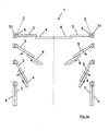
- FIG. 2a shows an embodiment of the method for opening and closing operation of the sliding-swing gate 1.
- the sliding-swing gate 1 has two door leaf assemblies, which are hinged to two outer rotary columns 5 with pivot axes 2, so that the door leaf assemblies in the opening movement away from each other and in the Closing movement to be moved towards each other. Shown are three positions above the opening movement of the door leaf assembly, wherein the pivoting movement and the telescopic movement of the door wings 3 and 4 is synchronous about the pivot axis 2. Both the pivoting movement and the linear movement, also referred to below as telescopic movement, is shown by respective arrows.
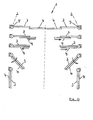
- FIG. 2b shows a variant of the method for opening and closing operation of the door leaf 3 and 4 of the sliding-swing gate 1.
- the opening operation of the door leaf arrangements begins with the linear movement of the second door leaf 4 along the first door leaf 3 in the direction of the respective rotary column 5 or pivot axis. 2 If the linear movement of the second door leaf 4 along the first door leaf 3 is completely executed, the pivoting movement for pivoting both door leaves 3 and 4 about the rotary column 5 begins.
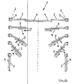
- Figure 2c shows a further variant of the method for opening and closing operation of the door leaf 3 and 4, wherein initially the linear movement of the second door leaf 4 along the first door leaf 3 in the respective direction to the respective rotary column 5 and pivot axis 2 begins. Is the linear motion
- only one pivoting area is claimed, which is determined by the width of the door leaves 3 and 4, respectively.
- an asynchronous linear and pivotal movement is only useful if the linear movement does not begin significantly after the beginning of the pivoting movement, otherwise the required pivoting range is required by the up to 2 times the width of the door leaf 3 and 4 respectively.
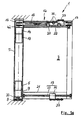
- FIG. 3a shows a side view of the sliding swing door 1, wherein the door is received between an upper and a lower part of a building body 36.
- the connection between the sliding pivot door 1 and the building body 36 is made possible by a ceiling bearing 7 and a bottom bearing 8.
- the door leaf assembly is shown simplistic only by the first door 3, which adjoins the rotary column 5, which extends between the ceiling bearing 7 and the bottom bearing 8.
- a first electric drive unit is rotationally fixed, which is represented by a first electric motor 6 and a first gear unit 9.
- the first electric drive unit is used to generate the pivoting movement of the door leaf assembly, wherein from the first gear unit 9, an output shaft 33 extends out, which cooperates with the bottom bearing 8. If the first electric motor 6 is put into operation, it can set the rotary column 5 in rotary motion, so that consequently the door leaf arrangement pivots about the pivot axis 2.
- a second electric drive unit is integrated, which by a second electric motor 13 and a second gear unit 14 is shown.
- the second electric drive unit acts on a bevel gear toothing 15, which sets a threaded spindle 11 in rotary motion.
- the threaded spindle 11 is integrated in the upper beam 20 of the first door leaf 3, wherein on the threaded spindle 11 a recirculating ball guide element 24 is received.
- the recirculating ball guide element 24 serves both to guide and to drive the second door leaf 4, wherein by rotation of the threaded spindle 11, the distance of the recirculating ball guide element 24 relative to the pivot axis 2 can be changed.
- the first door 3 has a lower leg 21, in which a guide element 23 is received.
- a recirculating ball guide element 24 is longitudinally movably guided, wherein the recirculating ball guide element 24 only assumes a guiding function in operative connection with the guide element 23 and is not driven, so that the guide element 23 and the recirculating ball guide element 24 together form a guide means 19.
- Both the upper side and the lower side recirculating ball guide element 24 shown is provided by means of connecting elements 37, to which the second door 4 is connected.
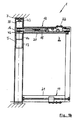
- FIG. 3b shows a further variant of the drive unit of the sliding-swing gate 1, wherein the door leaf assembly is again shown only by the first door 3.
- a threaded spindle 11 is received, on which in turn a recirculating ball guide element 24 is guided and driven.
- the drive of the threaded spindle 11 within the upper spar 20 is carried out according to this embodiment by the first electric drive unit, which is formed by the first electric motor 6 and the first gear unit 9.
- the gear unit 9 in turn acts on the bevel gear 15.
- a downstream gear unit 38 which cooperates with the ceiling bearing 7, that a pivoting movement in the rotary column 5 and consequently in the door leaf assembly can be generated .
- both the pivoting movement and the telescopic movement can be performed by means of a single electric drive unit, wherein the respective movements are kinematically coupled with each other.
- Figure 3c represents a further embodiment for a drive of the pivoting movement and the telescopic movement of the door leaf assembly.
- the first electric drive unit is in turn represented by a first electric motor 6, which is connected to a first gear unit 9.
- the rotary column 5 is formed in several parts and has a building-fixed portion 10.
- the building-fixed portion 10 performs no rotational movement, so that only both the upper part of the rotary column 5 and the lower part of the rotary column 5 perform a rotational movement and the non-moving , building-fixed section 10 as a third part center.
- Both the first electric motor 6 and the first electric gear unit 9 are rotationally fixed within the building-fixed section 10, so that via the output shaft 33, a torque can be transmitted to the other parts of the rotary column 5.
- the second electric drive unit is integrated on both the upper side and lower side, which are represented by the second electric motor 13 and the second gear unit 14 respectively on the top and on the bottom.
- the second electric drives are used to drive threaded spindles 11, wherein according to this embodiment, the sliding pivot door 1 is received both in the upper beam 20 and in the lower beam 21, a respective threaded spindle 11 and the second electric drives by means of a respective bevel gear 15 can be driven.
- recirculating ball guide elements 24 are guided, which, as already described in the preceding embodiments, are linearly driven by rotation of the threaded spindles 11 and move the second, not shown door 4 along the first door leaf 3.
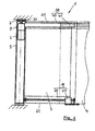
- FIG. 4 shows an embodiment of the sliding-swing gate 1, wherein the first electric drive unit, reproduced by the first electric motor 6 and the first gear unit 9, is accommodated in the rotary column 5 and the door leaf assembly by mechanical coupling of the output shaft 33 to the ceiling bearing 7 pivotally drives.
- a linear motor 39 is provided, which is shown as an example integrated in the upper beam 20.
- the linear motor 39 has a stator 40 in which a traveling magnetic field can be generated, so that a rotor 41 can be moved along the first door leaf 3.
- the stator 40 on the first door leaf 3 is received in a lateral arrangement within the upper spar 20 and points in the direction of the second door leaf 4.
- the arranged on the second door leaf 4 runner 41 is also received in a lateral arrangement, so that the stator 40 and the rotor 41 are adjacent to each other.
- the second door leaf 4 can be guided along the first door leaf 3.
- a guide means 19, formed by the guide element 23 and the recirculating ball guide element 24, is received in the lower beam 21 of the first door leaf 3.
- a guide in the region of the upper beam 20 is not shown in detail.
- the linear motor 39 with the stator 40 and the rotor 41 may be accommodated in the same way in the lower beam 21 of the sliding pivot door 1.
- FIG. 5a a further embodiment of a sliding-pivoting door 1 is shown, wherein in the rotary column 5, a first electric drive unit formed by the first electric motor 6 and the first gear unit 9, and a second electric drive unit, formed by the second electric motor 13 with the associated second gear unit 14, are received.
- the first electric drive unit is accommodated on the underside in the rotary column 5 and causes the pivoting movement of the door leaf assembly by operative connection of the output shaft 33 with the bottom bearing 8.
- Ceibmittettrieb 12 is added in the upper beam 20 of the first door leaf 3
- This comprises a first pulley 16 and a second pulley 17 around which an example formed as a toothed belt 18 traction means is looped.
- the first pulley 16 is received on the output shaft 42 of the second transmission unit 14. By driving the pulley 16, the toothed belt 18 can be set within the Oberholms 20 in motion.
- a carriage 22 On the toothed belt 18, a carriage 22 is attached, which is guided over rollers 35 within the upper spar 20. On the carriage 22 is in turn the Connecting element 37 for receiving the second door panel 4, not shown arranged.
- a guide means 19, formed by the guide member 23 and the ball circulation guide member 24, is received.
- a further connecting element 37 is arranged on the ball circulation guide element 24, so that the second door leaf 4 is received on the first door leaf 3 via the respective connecting elements 37.
- FIG. 5b shows a development of the embodiment according to FIG. 5a
- the carriage 22 is received in the upper beam 20 and driven via the traction mechanism drive 12.
- the guide means 19 In the lower beam 21 is the guide means 19, so that the guide and the drive through the Glasmitteitrieb 12 of the representation in FIG. 5a correspond.
- the second electric drive unit is provided, which is formed by the second electric motor 13 and the second gear unit 14.
- a downstream transmission unit 38 is connected to the output shaft 42.
- the downstream transmission unit 38 may be designed as a planetary gear and have a connecting shaft 43 which is rotatably connected to the ceiling bearing 7.
- FIG. 5c shows a sliding-swinging door 1, in turn, only the first door 3 is shown.
- the upper beam 20 and the lower beam 21 are interconnected by a side profile 44, which forms the main closing edge of the first door leaf 3.
- a guide angle 45 is mounted in order to guide the second door leaf 4 on the underside of the first door leaf 3.
- FIG. 6 shows a further embodiment of the sliding-swing door 1, wherein the door leaf assembly is in turn represented by the first door 3.
- the first and second electric drive units correspond to the embodiment according to FIG. 3a ,
- both the first electric motor 6 and the second electric motor 13 each have another motor winding body 26 to provide a redundant winding arrangement.
- the motor winding body 26 are attached to the end of the electric motors 6 and 13 via mechanical coupling elements 34 and also received in the rotary column 5.
- the redundant arrangement of further motor winding bodies 26 can be applied to any embodiment of the present sliding pivot door 1.
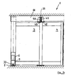
- FIGS. 7a and 7b a further embodiment of a sliding-pivoting door 1 is shown, wherein the door leaf assembly is represented by both the first door 3 and the second door leaf 4.
- the sliding swing door 1 is shown in the closed position, wherein further the first electric drive unit is shown, which is represented by the first electric motor 6 and the first gear unit 9 and cooperates via the output shaft 33 with the bottom bearing 8.
- the sliding swing door 1 is designed in each case with a mechanical overload device 25.
- FIG. 7a is the mechanical overload device 25 between the door leaves 3 and 4, wherein as shown in the FIG. 7b the mechanical overload device 25 is arranged in the region of the main closing edge 29 of the second door leaf 4.
- the mechanical overload device 25 is received in a stationary cross member 46 and has a spring element 47, which pushes a rolling element 48 into an undercut geometry 49.
- the rolling element 48 To open the door leaf assembly, the rolling element 48 must be moved against the force of the spring element 47 so that it pops out of the undercut geometry 49.
- the spring element 47 is received in a receiving body 50, which may be embedded within the stationary cross member 46.
- the door leaf assembly can also be pivoted manually, since the electric drive unit has no self-locking.
- An opening possibility is in FIG. 7c shown.
- FIG. 7c The door leaves 3 and 4 are pivotable about the respective pivot axis 2, wherein only the left pair of doors 3, 4 and the left door leaf assembly is opened by way of example.
- the door leaf arrangement only performs a pivoting movement, and the second door leaf 4 does not perform any linear movement along the first door leaf 3.
- Such an opening possibility is only given if there is no mechanical coupling between the pivoting movement of both door leaves 3 and 4 and the linear movement of the second door leaf 4 along the first door leaf 3.
- Such a mechanical coupling is for example according to FIG. 3b and according to FIG. 5b given.
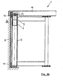
- FIGS. 8a and 8b a further embodiment of the inclusion of the sliding-swing gate 1 is shown within the building body 36.
- a vertical frame column 31 to be fixedly connected to the building is shown.
- the advantages are given by an improved recording and adjustment of the upper and lower bearing elements for the rotary column 5, thereby allowing the installation of the sliding swing door 1, regardless of the presence of a finished floor.
- different wall, passage or facade installation variants can be realized.
- the compensation of building tolerances by combining with different wall compensation elements can also be improved.
- a first electric drive unit is provided, which is represented by the first electric motor 6 and the first gear unit 9.
- the output shaft 33 cooperates with angle elements 51, which also serve for rotatably receiving the rotary column 5.
- FIG. 8a the frame column 31 is completely received within the building body 36, wherein, as shown in FIG. 8b a stationary cross member 46 is provided, the upper side forms the receptacle of the angle element 51.
- the invention is not limited in its execution to the above-mentioned preferred embodiment. Rather, a number of variants is conceivable, which makes use of the illustrated solution even with fundamentally different types of use.
- the sliding swing door 1 is not limited to an embodiment with only a first door leaf 3 and a second door leaf 4, since any further number of door leaves can be arranged consecutively.
Landscapes
- Engineering & Computer Science (AREA)
- Mechanical Engineering (AREA)
- Power-Operated Mechanisms For Wings (AREA)
- Wing Frames And Configurations (AREA)
Applications Claiming Priority (1)
| Application Number | Priority Date | Filing Date | Title |
|---|---|---|---|
| DE102009014869A DE102009014869A1 (de) | 2009-03-30 | 2009-03-30 | Schiebe-Schwenktür |
Publications (2)
| Publication Number | Publication Date |
|---|---|
| EP2236716A2 true EP2236716A2 (fr) | 2010-10-06 |
| EP2236716A3 EP2236716A3 (fr) | 2014-03-26 |
Family
ID=42329227
Family Applications (1)
| Application Number | Title | Priority Date | Filing Date |
|---|---|---|---|
| EP10002542.8A Withdrawn EP2236716A3 (fr) | 2009-03-30 | 2010-03-11 | Porte coulissante et pivotante |
Country Status (3)
| Country | Link |
|---|---|
| US (1) | US20100242366A1 (fr) |
| EP (1) | EP2236716A3 (fr) |
| DE (1) | DE102009014869A1 (fr) |
Cited By (6)
| Publication number | Priority date | Publication date | Assignee | Title |
|---|---|---|---|---|
| ITBO20100704A1 (it) * | 2010-11-25 | 2012-05-26 | Salvatore Picone | Sistema di apertura a movimentazione combinata |
| DE202011000884U1 (de) | 2011-04-14 | 2012-07-17 | Hücking GmbH | Möbel mit Schiebetür |
| CN106032736A (zh) * | 2015-03-11 | 2016-10-19 | 千藏工业株式会社 | 自动门装置 |
| CN107435495A (zh) * | 2016-04-26 | 2017-12-05 | 皇家宝盾国际私人有限责任公司 | 旋转门 |
| US10837225B2 (en) | 2016-03-02 | 2020-11-17 | Royal Boon Edam International B.V. | Revolving door |
| US11091953B2 (en) | 2017-05-08 | 2021-08-17 | Royal Boon Edam International B.V. | Revolving door |
Families Citing this family (31)
| Publication number | Priority date | Publication date | Assignee | Title |
|---|---|---|---|---|
| US8205387B2 (en) * | 2007-04-12 | 2012-06-26 | Stanley Black & Decker, Inc. | Delayed egress sliding door and method |
| US9617776B2 (en) * | 2010-03-31 | 2017-04-11 | Veritas Medical Solutions Llc | Motor driven door assembly |
| US8756864B2 (en) * | 2010-09-17 | 2014-06-24 | Stanley Black & Decker, Inc. | Slide door |
| US8627604B2 (en) | 2010-12-23 | 2014-01-14 | Stanley Black & Decker, Inc. | Bypass door |
| US8684477B1 (en) * | 2011-02-14 | 2014-04-01 | Joseph D Maresh | Cabinet door with retractable panel |
| GB2504229A (en) * | 2011-05-12 | 2014-01-22 | Maliform Pty Ltd | Improvements in bathing fixtures |
| KR101673905B1 (ko) * | 2012-04-30 | 2016-11-22 | 서민정 | 안전문 |
| CN103967375A (zh) * | 2013-12-08 | 2014-08-06 | 曹伟 | 自动平移开启式玻璃窗的使用控制方法 |
| JP6361067B2 (ja) * | 2014-06-30 | 2018-07-25 | 寺岡オート・ドアシステム株式会社 | 自動ドア装置 |
| US9976336B2 (en) * | 2014-07-11 | 2018-05-22 | B/E Aerospace, Inc. | Telescoping aircraft panel door |
| KR101644233B1 (ko) * | 2014-08-08 | 2016-07-29 | 박승규 | 공간활용 여닫이문 |
| CN104563778A (zh) * | 2014-12-08 | 2015-04-29 | 苏州沃斯麦机电科技有限公司 | 一种智能自适应门 |
| US9598887B2 (en) * | 2015-02-18 | 2017-03-21 | Margaret B. Reed | Hidden hinge door system and method for use in residential and commercial buildings |
| CN105587220B (zh) * | 2016-02-29 | 2018-09-11 | 深圳市凯森博格门窗系统有限公司 | 一种推拉平开门窗五金系统及其使用方法 |
| PL3571370T3 (pl) | 2017-01-19 | 2024-03-25 | Itab Shop Products Ab | Zastosowanie automatycznej bramki przejściowej w przypadku otwierania w sytuacji awaryjnej, oraz stanowiska kasowego |
| US10407960B2 (en) * | 2017-02-03 | 2019-09-10 | Assa Abloy Entrance Systems Ab | Automatically actuated door lock system |
| US20180251222A1 (en) * | 2017-03-01 | 2018-09-06 | B/E Aerospace, Inc. | Aircraft Lavatory Complex for People of Reduced Mobility |
| US10337228B1 (en) * | 2017-09-04 | 2019-07-02 | Dan A Matthews | Swinging pocket door |
| EP3495580A1 (fr) * | 2017-12-06 | 2019-06-12 | International Office Concept S.p.A. | Systeme de cloison avec porte coulissante |
| WO2019110660A1 (fr) * | 2017-12-08 | 2019-06-13 | Wolfgang Held | Bandeau pour meuble |
| US20190254486A1 (en) * | 2018-02-20 | 2019-08-22 | Bath Authority Llc Dba Dreamline | Automated door slider assembly |
| US11220852B2 (en) | 2019-05-02 | 2022-01-11 | Textron Innovations Inc. | Aircraft having versatile door systems |
| WO2021010819A1 (fr) * | 2019-07-18 | 2021-01-21 | Teh Lee Wah | Ensemble barrière pour portail |
| US20230374837A1 (en) * | 2020-03-23 | 2023-11-23 | Stoper Endüstriyel Ürünler Sanayi Ticaret Limited Sirketi | Motorized sliding folding panel mechanism |
| GB2596873B (en) * | 2020-07-10 | 2023-07-19 | Thompson Aero Seating Ltd | Actuation system |
| NL2027364B1 (en) * | 2021-01-22 | 2022-08-05 | Viewline B V | Sliding panel system |
| US11713616B2 (en) | 2021-08-31 | 2023-08-01 | Assa Abloy Entrance Systems Ab | Automatic door with a hinged swinging partial door |
| IT202100024818A1 (it) * | 2021-09-28 | 2023-03-28 | Paolo Fornasari | Sistema di supporto, di movimentazione e di occultamento di almeno una porta |
| CN114869081B (zh) * | 2022-06-07 | 2023-07-11 | 江苏经贸职业技术学院 | 一种基于智能家居的一体化床柜 |
| US12006760B2 (en) | 2022-09-29 | 2024-06-11 | Assa Abloy Entrance Systems Ab | Automatic door with biased open and manually closed external partial door |
| TWI819870B (zh) * | 2022-10-28 | 2023-10-21 | 緯創資通股份有限公司 | 傳動機構及包括其之殼體組件 |
Citations (1)
| Publication number | Priority date | Publication date | Assignee | Title |
|---|---|---|---|---|
| DE19600444A1 (de) | 1996-01-09 | 1997-07-10 | Dorma Gmbh & Co Kg | Schiebe-Schwenktür |
Family Cites Families (21)
| Publication number | Priority date | Publication date | Assignee | Title |
|---|---|---|---|---|
| US704887A (en) * | 1901-04-22 | 1902-07-15 | Frederic F Low | Door. |
| US877593A (en) * | 1907-07-18 | 1908-01-28 | Andrew Peirano | Grain-car door. |
| US1852608A (en) * | 1930-01-24 | 1932-04-05 | Hugh R Grable | Sliding and swinging door |
| US2895183A (en) * | 1954-10-21 | 1959-07-21 | Carl P Dumbolton | Door construction |
| US3750737A (en) * | 1972-05-01 | 1973-08-07 | R Woodward | Adjustable width folding door |
| FR2446917A1 (fr) * | 1979-01-18 | 1980-08-14 | Faiveley Sa | Porte coulissante a ouverture d'urgence |
| US4635699A (en) * | 1984-04-06 | 1987-01-13 | Covenant Manufacturing Co. | Retractable safety shield |
| US4619074A (en) * | 1985-08-12 | 1986-10-28 | Leung Ignatius Y P | Convertible door system |
| US5832980A (en) * | 1996-02-16 | 1998-11-10 | Nt Dor-O-Matic Inc. | Floating pivot sliding and swinging panel construction for doors and the like |
| US6161334A (en) * | 1997-02-11 | 2000-12-19 | North States Industries, Inc. | Child and pet security gate |
| US6481160B1 (en) * | 1999-02-04 | 2002-11-19 | The Stanley Works | Axial door operator |
| AU6210000A (en) * | 1999-07-13 | 2001-02-13 | Stanley Works Pty. Ltd., The | Door assembly with improved pivot connection |
| GB2398596A (en) * | 2003-02-21 | 2004-08-25 | Cova Security Gates Ltd | Folding leaf gate |
| US7458410B1 (en) * | 2003-11-28 | 2008-12-02 | Dan Bronner | Multiple door joining assembly |
| JP2006291666A (ja) * | 2005-04-14 | 2006-10-26 | Aska Corp | 車両用扉の開閉構造 |
| US7950439B2 (en) * | 2005-11-28 | 2011-05-31 | Victor Ray Anderson | Combination-action slide and hinge swinging door |
| US7685774B2 (en) * | 2005-12-30 | 2010-03-30 | Speyer Door And Window, Inc. | Closing system for sealing system of sliding door/window |
| US7451802B2 (en) * | 2006-01-25 | 2008-11-18 | Nabco Entrances, Inc. | Slidable door assemblies with automatic pivot latching |
| US7299852B1 (en) * | 2006-10-02 | 2007-11-27 | Shan-Chi Chuang | Vertical blind that is expanded and folded quickly and conveniently |
| US20090250176A1 (en) * | 2008-04-08 | 2009-10-08 | Versare Solutions, Inc. | Expandable portable wall partition |
| US8096342B2 (en) * | 2009-09-28 | 2012-01-17 | Assa Abloy Ip Ab | Door package |
-
2009
- 2009-03-30 DE DE102009014869A patent/DE102009014869A1/de not_active Withdrawn
-
2010
- 2010-03-11 EP EP10002542.8A patent/EP2236716A3/fr not_active Withdrawn
- 2010-03-30 US US12/750,269 patent/US20100242366A1/en not_active Abandoned
Patent Citations (1)
| Publication number | Priority date | Publication date | Assignee | Title |
|---|---|---|---|---|
| DE19600444A1 (de) | 1996-01-09 | 1997-07-10 | Dorma Gmbh & Co Kg | Schiebe-Schwenktür |
Cited By (11)
| Publication number | Priority date | Publication date | Assignee | Title |
|---|---|---|---|---|
| ITBO20100704A1 (it) * | 2010-11-25 | 2012-05-26 | Salvatore Picone | Sistema di apertura a movimentazione combinata |
| EP2458123A1 (fr) * | 2010-11-25 | 2012-05-30 | Salvatore Picone | Système d'ouverture avec mouvement combiné |
| DE202011000884U1 (de) | 2011-04-14 | 2012-07-17 | Hücking GmbH | Möbel mit Schiebetür |
| WO2012140044A1 (fr) | 2011-04-14 | 2012-10-18 | Hücking GmbH | Ensemble ferrure pour portes coulissantes et meuble à porte coulissante |
| CN106032736A (zh) * | 2015-03-11 | 2016-10-19 | 千藏工业株式会社 | 自动门装置 |
| CN106032736B (zh) * | 2015-03-11 | 2020-06-30 | 千藏工业株式会社 | 自动门装置 |
| US10837225B2 (en) | 2016-03-02 | 2020-11-17 | Royal Boon Edam International B.V. | Revolving door |
| CN107435495A (zh) * | 2016-04-26 | 2017-12-05 | 皇家宝盾国际私人有限责任公司 | 旋转门 |
| US20190063131A1 (en) * | 2016-04-26 | 2019-02-28 | Royal Boon Edam International B.V. | Revolving Door |
| US10612286B2 (en) * | 2016-04-26 | 2020-04-07 | Royal Boon Edam International B.V. | Revolving door |
| US11091953B2 (en) | 2017-05-08 | 2021-08-17 | Royal Boon Edam International B.V. | Revolving door |
Also Published As
| Publication number | Publication date |
|---|---|
| US20100242366A1 (en) | 2010-09-30 |
| DE102009014869A1 (de) | 2010-10-07 |
| EP2236716A3 (fr) | 2014-03-26 |
Similar Documents
| Publication | Publication Date | Title |
|---|---|---|
| DE102009014869A1 (de) | Schiebe-Schwenktür | |
| DE2637438C3 (de) | Elektrischer Fensterantrieb, insbesondere für Kraftfahrzeuge | |
| DE102007057936B4 (de) | Türkantenschutzeinrichtung | |
| DE60100925T2 (de) | Einziehbare Hubvorrichtung für Rollstühle | |
| EP2604778A1 (fr) | Paroi coulissante pliante, train de roulement et rail de guidage | |
| EP1314626A1 (fr) | Porte coulissante et pivotante pour véhicules, notamment porte des passagers pour véhicules de transport urbain de personnes | |
| EP3656960B1 (fr) | Cinématique pour volet de véhicule | |
| EP1505239A1 (fr) | Entraínement pour un battant, notamment entraínement rotatif pour une porte, une fenêtre ou similaire | |
| DE102006010755B4 (de) | Verstellvorrichtung für einen Schiebedachdeckel an einem Fahrzeug | |
| EP1507059B1 (fr) | Ferrure pour porte ou fenêtre à soulèvement et coulissement | |
| EP2165868B1 (fr) | Système de porte coulissante pivotante | |
| EP2071114A2 (fr) | Ensemble de porte avec actionneur de porte intégré | |
| DE10336074B3 (de) | Antrieb für einen Flügel, insbesondere Drehantrieb für eine Tür, ein Fenster oder dergleichen | |
| EP3385485A1 (fr) | Ferrure de meuble pour un mouvement combiné coulissant et pivotant d'une porte en plusieurs parties et meuble doté d'une telle ferrure de meuble | |
| DE69910465T2 (de) | Betätigungsvorrichtung für Tür- oder Fensterkonstruktionen mit schwenkbaren Flügelelementen | |
| EP3327236B1 (fr) | Dispositif d'ouverture et/ou fermeture d'un battant | |
| EP0989006A1 (fr) | Store de fenêtre à commande électromécanique, en particulier pour véhicules automobiles | |
| EP1707726B1 (fr) | Dispositif pour l'ouverture et la fermeture d'une fenêtre ou porte montée coulissante sur un cadre | |
| EP1488977A1 (fr) | Porte louvoyante coulissante pour véhicule. | |
| DE4002232C2 (de) | Antrieb für ein Falttor | |
| EP2088273B1 (fr) | Mécanisme d'ouverture et de fermeture pour portes pliables | |
| DE69117733T2 (de) | Vorrichtung zum Öffnen und Schliessen von mehreren Flügeln durch kombiniertes Schwenken und Schieben von denselben | |
| DE19622290C1 (de) | Elektromechanischer Antrieb für eine Schiebetür | |
| DE102015006741B4 (de) | Drehflügeltürantriebsvorrichtung mit Teleskopgestänge | |
| EP2039549B1 (fr) | Système de porte coulissante pivotante |
Legal Events
| Date | Code | Title | Description |
|---|---|---|---|
| PUAI | Public reference made under article 153(3) epc to a published international application that has entered the european phase |
Free format text: ORIGINAL CODE: 0009012 |
|
| AK | Designated contracting states |
Kind code of ref document: A2 Designated state(s): AT BE BG CH CY CZ DE DK EE ES FI FR GB GR HR HU IE IS IT LI LT LU LV MC MK MT NL NO PL PT RO SE SI SK SM TR |
|
| AX | Request for extension of the european patent |
Extension state: AL BA ME RS |
|
| PUAL | Search report despatched |
Free format text: ORIGINAL CODE: 0009013 |
|
| AK | Designated contracting states |
Kind code of ref document: A3 Designated state(s): AT BE BG CH CY CZ DE DK EE ES FI FR GB GR HR HU IE IS IT LI LT LU LV MC MK MT NL NO PL PT RO SE SI SK SM TR |
|
| AX | Request for extension of the european patent |
Extension state: AL BA ME RS |
|
| RIC1 | Information provided on ipc code assigned before grant |
Ipc: E05F 15/14 20060101ALI20140214BHEP Ipc: E05F 15/12 20060101ALI20140214BHEP Ipc: E05D 15/58 20060101AFI20140214BHEP |
|
| 17P | Request for examination filed |
Effective date: 20140926 |
|
| RBV | Designated contracting states (corrected) |
Designated state(s): AT BE BG CH CY CZ DE DK EE ES FI FR GB GR HR HU IE IS IT LI LT LU LV MC MK MT NL NO PL PT RO SE SI SK SM TR |
|
| STAA | Information on the status of an ep patent application or granted ep patent |
Free format text: STATUS: THE APPLICATION IS DEEMED TO BE WITHDRAWN |
|
| 18D | Application deemed to be withdrawn |
Effective date: 20140927 |