EP2240084B1 - Externer fixateurring - Google Patents
Externer fixateurring Download PDFInfo
- Publication number
- EP2240084B1 EP2240084B1 EP09707791.1A EP09707791A EP2240084B1 EP 2240084 B1 EP2240084 B1 EP 2240084B1 EP 09707791 A EP09707791 A EP 09707791A EP 2240084 B1 EP2240084 B1 EP 2240084B1
- Authority
- EP
- European Patent Office
- Prior art keywords
- ring
- flanges
- securing
- external fixator
- apertures
- Prior art date
- Legal status (The legal status is an assumption and is not a legal conclusion. Google has not performed a legal analysis and makes no representation as to the accuracy of the status listed.)
- Active
Links
Images




Classifications
-
- A—HUMAN NECESSITIES
- A61—MEDICAL OR VETERINARY SCIENCE; HYGIENE
- A61B—DIAGNOSIS; SURGERY; IDENTIFICATION
- A61B17/00—Surgical instruments, devices or methods
- A61B17/56—Surgical instruments or methods for treatment of bones or joints; Devices specially adapted therefor
- A61B17/58—Surgical instruments or methods for treatment of bones or joints; Devices specially adapted therefor for osteosynthesis, e.g. bone plates, screws or setting implements
- A61B17/60—Surgical instruments or methods for treatment of bones or joints; Devices specially adapted therefor for osteosynthesis, e.g. bone plates, screws or setting implements for external osteosynthesis, e.g. distractors, contractors
- A61B17/62—Ring frames, i.e. devices extending around the bones to be positioned
-
- A—HUMAN NECESSITIES
- A61—MEDICAL OR VETERINARY SCIENCE; HYGIENE
- A61B—DIAGNOSIS; SURGERY; IDENTIFICATION
- A61B17/00—Surgical instruments, devices or methods
- A61B17/56—Surgical instruments or methods for treatment of bones or joints; Devices specially adapted therefor
- A61B2017/564—Methods for bone or joint treatment
-
- Y—GENERAL TAGGING OF NEW TECHNOLOGICAL DEVELOPMENTS; GENERAL TAGGING OF CROSS-SECTIONAL TECHNOLOGIES SPANNING OVER SEVERAL SECTIONS OF THE IPC; TECHNICAL SUBJECTS COVERED BY FORMER USPC CROSS-REFERENCE ART COLLECTIONS [XRACs] AND DIGESTS
- Y10—TECHNICAL SUBJECTS COVERED BY FORMER USPC
- Y10T—TECHNICAL SUBJECTS COVERED BY FORMER US CLASSIFICATION
- Y10T29/00—Metal working
- Y10T29/49—Method of mechanical manufacture
- Y10T29/49826—Assembling or joining
- Y10T29/49947—Assembling or joining by applying separate fastener
- Y10T29/49963—Threaded fastener
Definitions
- the present disclosure relates in general to the field of external fixation device, and more specifically, to an external fixator ring and other external supports having a unique hole location and orientation for use as part of an external fixation system.
- external fixation devices are commonly used on both the upper and lower limbs for both adults and children in a variety of surgical procedures including limb lengthening, deformity correction and treatment of fractures, mal-unions, non-unions and bone defects.
- the Ilizarov external fixation procedure involves a rigid framework consisting of several rings or arches that are placed externally around the limb and attached to injured (e.g., due to fracture) or surgically separated (e.g., for limb lengthening and deformity correction) bone segments using special bone fasteners (wires and pins) inserted into the bone segment and connected to the related section of the external rigid framework.
- the opposite rings of the rigid framework are connected by either threaded or telescopic connection rods or by assembled uni-planar or multi-planar angular hinges, which allow the surgeon to adjust the relative position of the rings to each other longitudinally or angularly over a period of time.
- the external apparatus is stabilized into a fixed position and left on the bone segments until the fracture is healed or newly formed bone is completely or substantially mineralized, which could take up to an additional 3-6 months, depending on the nature of pathology and degree of deformity.
- Taylor Spatial Frame Another common external fixation device is a Taylor Spatial Frame as described in U.S. Patent Nos. 6,030,386 , 5,891,143 , and 5,776,132 .
- the Taylor Spatial Frame is a hexapod type of device based on a Stewart platform but shares many components and features of the Ilizarov apparatus.
- the Taylor Spatial Frame consists of two external fixator rings attached to bone segments by wires or half pins and connected together by 6 struts that may be lengthened or shortened as necessary.
- Adjustment of strut lengths allows manipulation of the bone segments in 6 axes (e.g., lengthening/shortening, external/internal rotation, anterior/posterior horizontal translation, medial/lateral horizontal translation, anterior/posterior angular translation, and medial/lateral angular translation) to correct linear, angular and rotational deformities simultaneously.
- the rings of the device include apertures or holes for attachment of wires and half pins and positioning of the struts and other connection elements. However, there are a finite number of holes on each ring, six of which are occupied with struts. This creates a positioning problem for wire and half pin attachment and placement of the additional connection rods due to the competition for holes in the ring.
- the configuration of the rings of the Taylor Spatial Frame requires the struts to be connected at the top or bottom of the rings.
- the rings are configured to receive only either ball joints in the holes of the rings or universal joints extending from the top or bottom surfaces of the rings. Both types of joints, however, have drawbacks.
- One drawback for using rings that are coupled to ball joints is that there is insufficient spatial clearance for the ball joints to effect some adjustments to the orientation of the struts and the rings.
- a drawback for using rings coupled to universal joints is the decrease in the functional length of the struts due to the space taken up by the length of the universal joints. Another drawback is the instability caused by universal joints.
- the universal joints each include at least one hinge connection, in which a pivot pin is commonly and loosely held by two rotating parts that are designed to rotate about the longitudinal axis defined by the pivoting pin. Due to the loose coupling between the rotating parts and the pivoting pin, a degree of undesirable translational movement is inherent in the design of the hinge connection and introduces instability to the Taylor Spatial Frame. Accordingly, the requirement of attaching the struts at the top or bottom of the rings ultimately leads to instability and limited range of motion in the Taylor Spatial Frame.
- the present disclosure provides an external fixator ring according to independent Claim 1, and a method of assembly of an external fixator device according to independent Claim 16.
- fixator ring While the making and using of various embodiments of the fixator ring according to the present disclosure are discussed in detail below, it should be appreciated that the present application provides many applicable inventive concepts that can be embodied in a wide variety of specific contexts.
- the specific embodiments discussed herein are merely illustrative of specific ways to make and use the fixation device disclosed herein and do not delimit the scope of the application, and their usage does not delimit the application, except as outlined in the claims.
- the present application discloses a fixator ring fabricated from a suitably strong and rigid material such as a metal, alloy, plastic, composite, or ceramic.
- the body portion of the ring includes substantially equally spaced apertures or holes positioned arcuately therein and extending through the upper ring surface to the lower ring surface, substantially equally spaced angled flanges extending radially from the outer surface of the ring and substantially equally spaced apertures that extend at least partially into the outer surface of the ring.
- the arcuately positioned holes are used to connect wires and half pins inserted to the bone segments while angled flanges and apertures are used for attachment of connection struts.
- the apertures are positioned obliquely in the angled flange to provide the optimal range of motion for the strut when connected to the fixator ring.
- struts can be connected to other apertures on outer or inner surfaces of the ring.
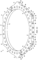
- FIGURE 1 is a top view of the fixator ring 10 of the present application.
- the fixator ring 10 includes a top surface 12, a bottom surface (not shown), an inner side surface (not shown) and an outer side surface (not shown).
- the fixator ring 10 has numerous angled flanges 14a, 14b, 14c, 14d, 14e and 14f extending from the outer side surface (not shown) to provide mounting surfaces for connection struts.
- the fixator angled flanges 14 may be placed at various positions on the fixator ring 10.
- the top surface 12 includes numerous top holes 16 that extend through the top surface 12 to the bottom surface (not shown).
- the top holes 16 may be used for attachment of wire and half pin fixation elements (bolts), threaded or telescopic connection rods, plates, posts or other device connection elements for connecting to the ring 10.
- the fixator ring 10 includes a top surface 12, a bottom surface (not shown), an inner side surface 18 and an outer side surface 20.
- the top surface 12 includes numerous top holes 16 that extend through the top surface 12 to the bottom surface (not shown).
- the top holes 16 may be used for attachment of wire and half pin fixation elements (bolts), threaded or telescopic connection rods, plates, posts or other device connection elements to the ring 10.
- the fixator ring 10 has angled flanges 14 extending from the outer side surface 20 to provide mounting surfaces 22a and 22b for connection struts.
- Each mounting surface 22a and 22b of the angled flanges 14 includes a threaded aperture 24 that extends into the outer surface 20 of the ring 10 and is adapted to provide attachment for connection struts (not shown).
- the outer side surface 20 includes numerous threaded apertures 26 that provide additional attachments for the struts or other connection elements.
- the inner side surface 18 includes threaded apertures 28 for receiving the struts or other connections element.
- the fixator ring 10 may include flanges 14 but not apertures 24 or 28. In some other examples, the fixator ring 10 may include apertures 24 or 28 but not flanges 14.
- an information indicator may be mounted onto or embedded into the fixator ring 10 or disposed proximate to the flanges 14.
- the information indicator may be in the form of a code, color, or serial number corresponding to relevant information. Examples of the relevant information embodied or represented by the information indicator may include the type of the external support, the size of the ring, flange identification information, etc.
- the information indicator may be in the form of a bar code, magnetic strip, or radio frequency identifier that could be read by a reading device to retrieve the relevant information.
- the information indicator may be any other device suitable to embody or represent information or a combination of the types of indicators discussed in the present application.
- the number of threaded outer apertures 26 and threaded inner apertures 28 may vary depending on the size of the ring as well as the number of threaded outer apertures 26 in the angled flanges 14.
- the outer apertures 26, inner apertures 28 and angled flange aperture 24 may be configured to accept other connection elements of the external fixator frame 10.
- the angled flanges 14 may be placed at various positions on the outer surface 20 of the fixator ring 10. Generally, the angled flanges 14 are placed at a geometric position about the fixator ring 10.
- the fixator ring 10 may include one ore more angled flanges 14 positioned equidistant from each other about the fixator ring 10; however the distances need not be equidistant and may be of any convenient distance or spacing.
- the angled flanges 14 may be integrally connected or releasably coupled to the fixator ring 10. Detachable angled flanges 14 may be particularly advantageous in some embodiments because they allow for more flexibility in the placement of struts.
- fixator systems for foot support may require additional struts to provide firmer support or to accommodate various shapes of the ring.
- the angled flanges 14 may be of different shapes and different sizes to provide different ranges of motion for the struts connected to the flanges 14.
- other shapes of the angled flanges 14 include rounded flanges polygonal flanges, triangular flanges, or square flanges, when viewed from the top surface 12.
- the flanges 14 are angled at 120 degrees to allow the connecting struts to have a maximum range of motion.
- the term "angled" as used in the present disclosure refers to the angular orientation of a first mounting surface relative to a second mounting surface.
- the illustrated fixator ring 10 includes a top surface 12, a bottom surface (not shown), an inner side surface 18 and an outer side surface 20.
- the fixator ring 10 further has trapezoidal flanges 15 extending from the outer side surface 20 to provide mounting surfaces 22a and 22b for connection struts.
- Each mounting surface 22a and 22b of the trapezoidal flanges 15 includes an aperture 25 defined therein.
- the apertures 25 each have a smooth (rather than threaded) inner surface and are adapted to receive studs 27 (shown in FIGURES 3C TO 3G) to provide attachment for connection struts (not shown).
- the trapezoidal flanges 15 each also have a securing surface 23 disposed between the mounting surfaces 22a and 22b.
- the securing surface 23 has an aperture 29 defined therein, and the aperture 29 is operable to receive a screw 31 (shown in FIGURE 3C ) for locking the studs 27 in place.
- the screw 31 is a set screw.
- FIGURE 3C is a partial sectional view of the fixator ring 10 of FIGURE 3B when viewed from the top in the direction indicated by arrows 7.
- the apertures 25 and 29 meet at a recess 33 within the flange 15, which provides room for the studs 27 and set screw 31 to engage with one another inside the flange 15.
- the studs 27 each have an end portion that is exposed in the recess 33 when the studs 27 are received in the apertures 25 as shown in FIGURE 3C .
- the set screw 31 is inserted into the aperture 29 to engage the end portions of studs 27.
- the apertures 25 are aligned at an angle that substantially corresponds to the shape of the angled tip of the set screw 31, thereby increasing the contact area between the studs 27 and the set screw 31.
- the number and orientation of the apertures 25 and 29 can vary in some embodiments to accommodate various design needs.
- the alignment of the apertures 25 can be altered to accommodate different sizes and configurations of the set screw 31 and/or studs 27.
- dynamic loading on the contact surface between the studs 27 and the set screw 31 can cause the contact surface to deform and ultimately cause the studs 27 to become loosened.
- the apertures 25 and 29 can be configured to receive studs 27 having grooves defined therein to allow for optimal gripping and to accommodate for the dynamic loading of the contact surface.
- FIGURE 3D is a partial sectional view of an exemplary embodiment of the flange 15 of FIGURE 3B .
- the flange 15 is configured to receive studs 27 having grooves 35 defined therein.
- the grooves 35 are defined in the end portions of the studs 27, such that, when the studs 27 are received in the apertures 25, grooves 35 are exposed in the recess 33 as shown in FIGURE 3D .
- the studs 27 are aligned at an angle that allows the set screw 31 to be inserted into the aperture 29 and engage the grooves 35 of both studs 27, thereby substantially locking the studs 27 in place.
- FIGURE 3E Shown in FIGURE 3E is another exemplary embodiment of the flange 15 of FIGURE 3B .
- the stud 27 includes a conical tip 37 and grooves 35 defined therein.
- the conical tip 37 allows for better guidance for the insertion of the stud 27 and increased contact surface between the stud 27 and the walls of the recess 33 for improved stability.
- the inclusion of a conical tip 37 increases the effective length of the stud 27 and further improves the stability of the stud 27 in aperture 25.
- FIGURE 3F is a partial sectional view of another exemplary embodiment of the flange 15 of FIGURE 3B .
- the illustrated set screw 31 includes an engagement portion 39 pivotally mounted onto tip 41, and the engagement portion 39 is operable to swivel until it is securely fit into the grooves 35 of both studs 27.
- the engagement portion 39 allows the binding load on the studs 27 to be distributed more equally between the studs 27.
- FIGURE 3G a partial sectional view of yet another exemplary embodiment of the flange 15 of FIGURE 3B .
- the securing surface 23 of the flange 15 includes two apertures 29 defined therein, each operable to receive a set screw 31 for substantially locking one of the two studs 27.
- the studs 27 can be independently locked by a different set screw 31.
- FIGURE 4 is a perspective view of a fixator ring 10 that is operable to receive a positional marker 70 (shown in FIGURE 5 ).
- a positional marker 70 can be any markers used in orthopedic applications, such as a radiological marker used to determine the spatial orientation of the fixator ring 10.
- the fixator ring 10 includes a top surface 12, a bottom surface (not shown), an inner side surface 18 and an outer side surface 20.
- the fixator ring 10 further has trapezoidal flanges 15 as described above with reference to FIGURES 3A to 3G .
- the fixator ring 10 includes at least a pair of recessed portions 72 defined therein for receiving the nodules 74 of the marker 70 and substantially securing the marker 70 in one orientation.
- the number and placement of the pair of recessed portions 72 can vary in different embodiments. In the exemplary embodiment showing in FIGURE 4 , there are four pairs of recessed portions 72 defined in the outer side surface 20 of the fixator ring 10 and spaced apart at different distances. In some embodiments, the pairs of recessed portions 72 can be equally spaced. In some other embodiments, pairs of recessed portions 72 may be defined in the inner side surface 18, the top surface 12 , or the bottom surface (not shown).
- the marker 70 has a pair of nodules 74 that would fit tightly into the recessed portions 72, which provides two points of attachment. This allows for a substantially secure coupling of the marker 70 to the fixator ring 10 because having two points of attachment prevents the marker 70 from experiencing rotational movements. It is to be appreciated that other suitable securing mechanisms can be used for securing the marker 70 to the fixator ring 10.
- the marker 70 could be modified to include a rectangular peg instead of a pair of nodules 74, and in such cases, a corresponding rectangular recessed portion defined in the fixator ring 10 instead of a pair of recessed portions 72 would be sufficient to prevent rotational movements of the marker 70.
- FIGURE 6 is a perspective view of an external fixator ring system 40.
- the fixator ring 42a includes a top surface 12, a bottom surface (not shown), an inner side surface 18 and an outer side surface 20.
- the fixator ring 42a has angled flanges 50, 52 and 54 extending from the outer side surface 20 to provide mounting surfaces 22a and 22b for connection struts 58.
- the top surface 12 includes numerous top holes 16 that extend through the top surface 12 to the bottom surface (not shown).
- the top holes 16 may be used for attachment of wire and half pin fixation elements (bolts), threaded or telescopic connection rods, plates, posts or other device connection elements to the ring 42a.
- fixator angled flanges 50, 52, and 54 also include threaded outer apertures (not shown) to provide attachment for connection struts 58a, 58b, 58c, 58d, 58e and 58f.
- the outer side surface 20 includes numerous threaded apertures 26 that provide additional attachments for the struts 58 or other connection elements (not shown).
- the second fixator ring 42b includes a top surface 12, a bottom surface (not shown), an inner side surface 18 and an outer side surface 20.
- the fixator ring 42b has angled flanges 50b, 52b and 54b extending from the outer side surface 20 to provide mounting surfaces 22a and 22b for connection struts 58.
- the top surface 12 includes numerous top holes 16 that extend through the top surface 12 to the bottom surface (not shown). The top holes 16 may be used for attachment of wire and half pin fixation elements (bolts), threaded or telescopic connection rods, plates, posts or other device connection elements to the ring 42b.
- fixator angled flanges 50, 52 and 54 also include threaded outer apertures (not shown) to provide attachment for connection struts 58a, 58b, 58c, 58d, 58e and 58f.
- the outer side surface 20 includes numerous threaded apertures 26 that provide additional attachments for the struts or other connection elements (not shown).
- the shape of the fixator rings 42a and 42b as shown FIGURE 6 is substantially circular, it is to be appreciated that the shape of the fixator rings 42a and 42b can vary to accommodate the physical contour of various body parts to which the fixation system 40 would be attached.
- the fixator rings 42a and 42b can be configured to have an oval shape, D-shape, U-shape, C-shape, or other irregular shapes.
- an elliptical fixator ring (not shown) may be particularly advantageous. The insertion of pins or wires into a patient's limb can cause the surrounding tissue to swell unevenly, and in such a case, an elliptical fixator ring can accommodate the uneven swelling better than a circular ring can.
- the fixator rings 42a and 42b may be a complete ring (full ring) or a segment or portion of a ring (e.g., half ring, 1/3 ring, 1/4 ring, 3/8 ring, 5/8 ring, 2/3 ring, 3/4 ring, and other) that is either used alone or joined with other segments or portions of the ring to form a fixator ring (not shown).
- the fixator rings 42a and 42b may be constructed of any material that provides the structural rigidity necessary for fixation such as metal, alloy, carbon fiber, plastic, ceramic and so forth.
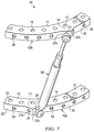
- FIGURE 7 is a side view of one embodiment of a fixator ring system 40.
- the fixator ring system 40 of the present application is illustrated as a portion of the specific design for simplicity.
- the fixator rings 42a and 42b include a top surface 12, a bottom surface (not shown), an inner side surface (not shown) and an outer side surface 20.
- the fixator rings 42a and 42b have an angled flanges 14 extending from the outer side surface 20 to provide mounting surfaces 22a and 22b for connection struts 58.
- the top surface 12 includes numerous top holes 16 that extend through the top surface 12 to the bottom surface (not shown).
- the top holes 16 may be used for attachment of wire and half pin fixation elements (bolts), threaded or telescopic connection rods, plates, posts or other device connection elements to the ring 42.
- the angled flanges 14 also include threaded outer apertures 24 to provide attachment for connection struts 58.
- a single connecting strut 58 connects the fixator rings 42a and 42b.
- the outer side surface 20 includes numerous threaded apertures 26 that provide additional attachments for the struts 58 or other connection elements (not shown).
- a connecting strut 58 is disposed between the first external fixator ring 42a and the second external fixator ring 42b for the sake of simplicity.
- numerous connecting rods 58 may be attached at various positions about the external fixator rings, that the angle of the connecting rod 58 relative to the first external fixator ring 42a and the second external fixator ring 42b may be varied, and that the length of the connecting rod 58 may be varied and adjusted.
- the present application provides a method and apparatus for stabilization using multiple external fixator rings as a single device.
- a first external fixator ring having 6 equidistant angled flanges is connected to a second external fixator ring having 6 equidistant angled flanges as above.
- a third external fixator ring is connected to the first external fixator ring, the second external fixator ring or both using the three unused angled flanges.
- compositions of the invention can be used to achieve methods of the invention.
- the words “comprising” (and any form of comprising, such as “comprise” and “comprises”), “having” (and any form of having, such as “have” and “has”), "including” (and any form of including, such as “includes” and “include”) or “containing” (and any form of containing, such as “contains” and “contain”) are inclusive or open-ended and do not exclude additional, unrecited elements or method steps.
- compositions and/or methods disclosed and claimed herein can be made and executed without undue experimentation in light of the present disclosure. While the compositions and methods of this invention have been described in terms of preferred embodiments, it will be apparent to those of skill in the art that variations may be applied to the compositions and/or methods and in the steps or in the sequence of steps of the method described herein without departing from the concept, spirit and scope of the invention. All such similar substitutes and modifications apparent to those skilled in the art are deemed to be within the scope of the invention as defined by the appended claims.
Landscapes
- Health & Medical Sciences (AREA)
- Orthopedic Medicine & Surgery (AREA)
- Life Sciences & Earth Sciences (AREA)
- Surgery (AREA)
- Medical Informatics (AREA)
- Engineering & Computer Science (AREA)
- Biomedical Technology (AREA)
- Heart & Thoracic Surgery (AREA)
- Nuclear Medicine, Radiotherapy & Molecular Imaging (AREA)
- Molecular Biology (AREA)
- Animal Behavior & Ethology (AREA)
- General Health & Medical Sciences (AREA)
- Public Health (AREA)
- Veterinary Medicine (AREA)
- Surgical Instruments (AREA)
- Orthopedics, Nursing, And Contraception (AREA)
Claims (17)
- Externer Fixateurring (10), aufweisend:einen Ring mit einer durch diesen hindurch gebildeten zentralen Öffnung, wobei der Ring eine innere (18) und eine äußere (20) Ringoberfläche sowie eine obere (12) und untere Ringoberfläche aufweist;einen oder mehrere Flansche, die sich von der inneren (18) oder der äußeren Oberfläche (20) radial weg erstrecken,dadurch gekennzeichnet, das jeder von dem einen oder den mehreren Flanschen (14, 15) wenigstens eine erste (22a) und eine zweite (22b) Befestigungsfläche aufweisen, die in der inneren (18) oder äußeren (20) Oberfläche gebildet sind, wobei jede von der ersten (22a) und der zweiten (22b) Befestigungsfläche (22a, 22b) eine in dieser gebildete Öffnung (24, 25) zur Aufnahme einer Sicherungsvorrichtung aufweist; wobei die erste (22a) und die zweite (22b) Befestigungsfläche zueinander geneigt sind und die Öffnungen (24, 25) in dem Flansch (14, 15) schräg angeordnet sind.
- Externer Fixateurring (10) nach Anspruch 1,
wobei die Öffnung (24) eine mit Gewinde versehene Innenfläche aufweist und die Sicherungsvorrichtung einen Gewindebolzen aufweist. - Externer Fixateurring (10) nach Anspruch 1,
wobei die Öffnung (25) eine glatte Innenfläche aufweist und die Sicherungsvorrichtung einen Bolzen (27) mit einem Endbereich aufweist, wobei der Endbereich des Bolzens eine darin gebildete Nut (35) aufweist, und wobei der Fixateurring (10) ferner trapezförmige Flansche (15) aufweist, die ebenfalls eine Sicherungsfläche (23) aufweisen, die zwischen den Befestigungsflächen (22a, 22b) angeordnet ist, wobei in der Sicherungsfläche (23) eine Gewindebohrung (29) gebildet ist, die betriebsmäßig zum Aufnehmen einer Schraube (31) ausgebildet ist, wobei die Schraube (31) betriebsmäßig dazu ausgebildet ist, mit der Nut (35) des Bolzens zusammenzuwirken, wenn die Schraube (31) in der Gewindebohrung (29) aufgenommen ist, um dadurch den Bolzen (27) im Wesentlichen in seiner Position zu verriegeln. - Externer Fixateurring (10) nach Anspruch 3,
wobei die Schraube (31) eine Stellschraube ist. - Externer Fixateurring (10) nach Anspruch 1,
der weiterhin eine oder mehrere Ringöffnungen (16) aufweist, die sich durch die obere Ringoberfläche (12) zu der unteren Ringoberfläche erstrecken. - Externer Fixateurring (10) nach Anspruch 1,
wobei der eine oder die mehreren Flansche (14, 15) eine Mehrzahl von Flanschen (14, 15) beinhalten, wobei die Flansche (14, 15) entlang der äußeren Oberfläche des Rings gleiche Abstände aufweisen. - Externer Fixateurring (10) nach Anspruch 1,
wobei der eine oder die mehreren Flansche (14, 15) sechs Flansche (14, 15) aufweisen, die in einer radialen Beabstandung von ca. 60 Grad entlang der äußeren Oberfläche des Rings angeordnet sind. - Externer Fixateurring (10) nach Anspruch 1,
der weiterhin eine Mehrzahl von Informationsanzeigen aufweist, die in der Nähe von jedem von dem einen oder den mehreren Flanschen (14, 15) angeordnet sind. - Externer Fixateurring (10) nach Anspruch 1,
weiterhin aufweisend:eine oder mehrere Öffnungen (16), die sich durch die obere Ringoberfläche (12) zu der unteren Ringoberfläche erstrecken;eine oder mehrere Strebenverbindungsöffnungen (26, 28), die in der inneren oder der äußeren Oberfläche gebildet sind, wobei die eine oder die mehreren Strebenverbindungsöffnungen (26, 28) sich zumindest teilweise in die innere (18) oder die äußere (20) Oberfläche hinein erstrecken, wobei jede von der einen oder den mehreren Strebenverbindungsöffnungen (26, 28) betriebsmäßig dazu ausgebildet ist, eine Sicherungsvorrichtung aufzunehmen;wobei es sich bei der Sicherungsvorrichtung, die in jeder der in der ersten (22a) und der zweiten (22b) Befestigungsfläche (22a, 22b) gebildeten Öffnungen (24, 25) aufgenommen ist, um ein zusätzliches Verbindungselement in Bezug auf die in den Strebenverbindungsöffnungen (26, 28) aufnehmbare Sicherungsvorrichtung handelt. - Externer Fixateurring (10) nach Anspruch 9,
wobei die eine oder die mehreren Strebenverbindungsöffnungen (28) in der inneren Ringoberfläche gebildet sind. - Externer Fixateurring (10) nach Anspruch 9,
wobei die eine oder die mehreren Strebenverbindungsöffnungen (26) in der äußeren Ringoberfläche gebildet sind. - Externer Fixateurring (10) nach Anspruch 9,
der weiterhin eine an dem Ring angeordnete Informationsanzeige aufweist. - Externer Fixateurring (10) nach Anspruch 9,
der weiterhin einen Sicherungsmechanismus zum Anbringen eines Markers (70) an dem Ring aufweist. - Externer Fixateurring (10) nach Anspruch 13,
wobei der Sicherungsmechanismus ein Paar Aussparungsbereiche (72) aufweist, die in der äußeren (20) oder inneren (18) Oberfläche des Rings (10) gebildet sind, und wobei der Marker (70) ein Paar Erhebungen (74) aufweist, die an einer Oberfläche des Markers (70) angeordnet sind, wobei die Erhebungen (74) betriebsmäßig dazu ausgebildet sind, fest in die Aussparungsbereiche zu passen. - Externer Fixateurring (10) nach Anspruch 14,
wobei der Sicherungsmechanismus einen rechteckigen Aussparungsbereich aufweist, der in der äußeren (20) oder inneren (18) Oberfläche des Rings (10) gebildet ist, und wobei der Marker (70) einen rechteckigen Zapfen aufweist, der an einer Oberfläche des Markers (70) angeordnet ist, wobei der Zapfen betriebsmäßig dazu ausgebildet ist, fest in die Aussparungsbereiche zu passen. - Verfahren zum Zusammenbauen einer einer externen Fixationsvorrichtung (40), wobei das Verfahren folgende Schritte aufweist:Bereitstellen eines ersten und eines zweiten externen Fixateurrings (42a, 42b), wobei der erste und der zweite Ring (42a, 42b) jeweils eine durch diese hindurch gebildete zentrale Öffnung aufweisen, wobei der erste und der zweite Ring (42a, 42b) ferner jeweils eine innere (18) und eine äußere (20) Oberfläche sowie einen oder mehrere Flansche (14, 15) aufweisen, die sich von der inneren (18) oder der äußeren (20) Oberfläche radial weg erstrecken, wobei jeder von dem einen oder den mehreren Flanschen (14, 15) wenigstens eine erste (22a) und eine zweite (22b) Befestigungsfläche aufweist, die in der inneren (18) oder äußeren (20) Oberfläche gebildet sind, wobei jede von der ersten (22a) und der zweiten (22b) Befestigungsfläche (22a, 22b) eine in dieser gebildete Öffnung (24, 25) zur Aufnahme einer Sicherungsvorrichtung aufweist; wobei die erste (22a) und die zweite (22b) Befestigungsfläche zueinander geneigt sind und die Öffnungen (24, 25) in dem Flansch (14, 15) schräg angeordnet sind;Bereitstellen einer Ringverbindungsstrebe (58a, 58b, 58c, 58d, 58e, 58f) mit einem ersten und einem zweiten Endbereich;Verbinden einer ersten und einer zweiten Sicherungsvorrichtung mit dem ersten und dem zweiten Endbereich der Ringverbindungsstrebe (58a, 58b, 58c, 58d, 58e, 58f);Anbringen der Ringverbindungsstrebe (58a, 58b, 58c, 58d, 58e, 58f) an dem ersten und dem zweiten Ring unter Sicherung der ersten Sicherungsvorrichtung in der Öffnung (24, 25) in dem einen oder den mehreren Flanschen (14, 15) des ersten Rings (42a) und Sicherung der zweiten Sicherungsvorrichtung in der Öffnung in dem einen oder den mehreren Flanschen (14, 15) des zweiten Rings (42b).
- Verfahren nach Anspruch 16,
wobei die Öffnung in dem einen oder den mehreren Flanschen (15) des ersten Rings eine mit Gewinde versehene Innenfläche aufweist und die erste Sicherungsvorrichtung eine Gewindeschraube aufweist, und wobei ferner das Sichern der ersten Sicherungsvorrichtung in der Öffnung in dem einen oder den mehreren Flanschen des ersten Rings das Einsetzen der Gewindeschraube in die Öffnung beinhaltet; oder
das Verfahren nach Anspruch 16,
wobei die Öffnung in dem einen oder den mehreren Flanschen (14) eine glatte Innenfläche aufweist und die erste Sicherungsvorrichtung einen Bolzen (27) mit einem Endbereich aufweist, wobei in dem Endbereich des Bolzens (27) eine Nut (35) gebildet ist, und wobei ferner der Fixateurring trapezförmige Flansche (15) aufweist, die ebenfalls eine zwischen den Befestigungsflächen (22a, 22b) angeordnete Sicherungsfläche (23) aufweisen, wobei in der Sicherungsfläche (23) eine Gewindebohrung (29) gebildet ist, die betriebsmäßig zum Aufnehmen einer Schraube (31) ausgebildet ist, und wobei ferner die Sicherung der ersten Sicherungsvorrichtung in der Öffnung in dem einen oder den mehreren Flanschen des ersten Rings das Einsetzen einer ersten Schraube (31) in die Gewindebohrung (29) zum Zusammenwirken mit der Nut (35) der Strebe beinhaltet, wenn die Schraube (31) in der Gewindebohrung (29) aufgenommen wird.
Applications Claiming Priority (2)
| Application Number | Priority Date | Filing Date | Title |
|---|---|---|---|
| US2639608P | 2008-02-05 | 2008-02-05 | |
| PCT/US2009/033258 WO2009100247A1 (en) | 2008-02-05 | 2009-02-05 | External fixator ring |
Publications (3)
| Publication Number | Publication Date |
|---|---|
| EP2240084A1 EP2240084A1 (de) | 2010-10-20 |
| EP2240084A4 EP2240084A4 (de) | 2013-12-25 |
| EP2240084B1 true EP2240084B1 (de) | 2016-05-11 |
Family
ID=40952460
Family Applications (1)
| Application Number | Title | Priority Date | Filing Date |
|---|---|---|---|
| EP09707791.1A Active EP2240084B1 (de) | 2008-02-05 | 2009-02-05 | Externer fixateurring |
Country Status (5)
| Country | Link |
|---|---|
| US (2) | US9295493B2 (de) |
| EP (1) | EP2240084B1 (de) |
| JP (2) | JP5571001B2 (de) |
| ES (1) | ES2595355T3 (de) |
| WO (1) | WO2009100247A1 (de) |
Families Citing this family (36)
| Publication number | Priority date | Publication date | Assignee | Title |
|---|---|---|---|---|
| US8419733B2 (en) * | 2007-08-16 | 2013-04-16 | Nutek Orthopedics, Inc. | External fixation apparatus with adjustable pin clamping means |
| WO2009100247A1 (en) | 2008-02-05 | 2009-08-13 | Texas Scottish Rite Hospital For Children | External fixator ring |
| JP5507472B2 (ja) | 2008-02-08 | 2014-05-28 | テキサス スコティッシュ ライト ホスピタル フォー チルドレン | 創外固定支柱 |
| EP2249721B1 (de) | 2008-02-12 | 2017-07-05 | Texas Scottish Rite Hospital For Children | Schnell einstellbare externe fixations-verbindungsstange |
| WO2009105479A1 (en) | 2008-02-18 | 2009-08-27 | Texas Scottish Rite Hospital For Children | Tool and method for external fixation strut adjustment |
| US8858555B2 (en) | 2009-10-05 | 2014-10-14 | Stryker Trauma Sa | Dynamic external fixator and methods for use |
| GB201008281D0 (en) | 2010-05-19 | 2010-06-30 | Nikonovas Arkadijus | Indirect analysis and manipulation of objects |
| US8945128B2 (en) | 2010-08-11 | 2015-02-03 | Stryker Trauma Sa | External fixator system |
| EP2417924B1 (de) | 2010-08-11 | 2015-07-01 | Stryker Trauma SA | Externes Befestigungssystem |
| US11141196B2 (en) | 2010-08-11 | 2021-10-12 | Stryker European Operations Holdings Llc | External fixator system |
| WO2012023876A1 (en) | 2010-08-20 | 2012-02-23 | Amei Technologies, Inc. | Method and system for roentgenography-based modeling |
| US9469026B2 (en) * | 2010-11-22 | 2016-10-18 | Soteria Medical B.V. | Motor system, motor, and robot arm device comprising the same |
| US9265529B2 (en) * | 2010-11-30 | 2016-02-23 | Nikolaj Wolfson | Orthopedic fixation systems and methods |
| US9101398B2 (en) | 2012-08-23 | 2015-08-11 | Stryker Trauma Sa | Bone transport external fixation frame |
| US9757153B2 (en) * | 2012-09-06 | 2017-09-12 | Wright Medical Technology, Inc. | External fixator |
| US8574232B1 (en) | 2012-11-13 | 2013-11-05 | Texas Scottish Hospital for Children | External fixation connection rod for rapid and gradual adjustment |
| JP6382293B2 (ja) | 2013-03-13 | 2018-08-29 | デピュイ・シンセス・プロダクツ・インコーポレイテッド | 外部骨固定装置 |
| US9039706B2 (en) | 2013-03-13 | 2015-05-26 | DePuy Synthes Products, Inc. | External bone fixation device |
| US9962188B2 (en) | 2013-10-29 | 2018-05-08 | Cardinal Health 247. Inc. | External fixation system and methods of use |
| US9936975B2 (en) | 2014-09-09 | 2018-04-10 | Integra Lifesciences Corporation | External fixation system |
| US10010346B2 (en) | 2016-04-20 | 2018-07-03 | Stryker European Holdings I, Llc | Ring hole planning for external fixation frames |
| US10010350B2 (en) | 2016-06-14 | 2018-07-03 | Stryker European Holdings I, Llc | Gear mechanisms for fixation frame struts |
| US10835318B2 (en) | 2016-08-25 | 2020-11-17 | DePuy Synthes Products, Inc. | Orthopedic fixation control and manipulation |
| US10306984B2 (en) * | 2016-08-30 | 2019-06-04 | The Boeing Company | Toroidal support structures |
| US10874433B2 (en) | 2017-01-30 | 2020-12-29 | Stryker European Holdings I, Llc | Strut attachments for external fixation frame |
| US11439436B2 (en) | 2019-03-18 | 2022-09-13 | Synthes Gmbh | Orthopedic fixation strut swapping |
| US11304757B2 (en) | 2019-03-28 | 2022-04-19 | Synthes Gmbh | Orthopedic fixation control and visualization |
| US11596442B2 (en) | 2019-06-21 | 2023-03-07 | Texas Scottish Right Hospital for Children | Dynamization tabs providing component interconnectivity for external fixation devices |
| EP4084711A4 (de) | 2020-01-02 | 2024-01-03 | ZKR Orthopedics, Inc. | Implantat zur neuausrichtung der patellasehne mit veränderbarer form |
| US11334997B2 (en) | 2020-04-03 | 2022-05-17 | Synthes Gmbh | Hinge detection for orthopedic fixation |
| US12303396B2 (en) | 2020-05-11 | 2025-05-20 | Zkr Orthopedics, Inc. | Adjustable patellar tendon realignment implant |
| US12514615B2 (en) | 2021-05-31 | 2026-01-06 | Kiran Saldanha Limited | External fixator system with custom assembled struts |
| US11457965B1 (en) | 2021-11-12 | 2022-10-04 | University Of Utah Research Foundation | Rotational guided growth devices, systems, and methods |
| TR2022013276A2 (tr) * | 2022-08-23 | 2023-02-21 | Exvet Medikal Danismanlik Yazilim Veterinerlik Hizmetleri Sanayi Ve Ticaret Ltd Sirketi | Kemi̇k tespi̇t aparati |
| AU2024334108A1 (en) | 2023-08-29 | 2026-02-26 | Zkr Orthopedics, Inc. | Multiplanar tendon realignment implants and related systems and methods |
| WO2025193752A1 (en) | 2024-03-11 | 2025-09-18 | Stevens Peter M | Spiral growth tether systems and methods |
Family Cites Families (87)
| Publication number | Priority date | Publication date | Assignee | Title |
|---|---|---|---|---|
| GB421788A (en) | 1933-06-29 | 1934-12-31 | Eloi Renevey | Apparatus for the treatment of bone-fractures |
| US2238870A (en) | 1939-02-04 | 1941-04-15 | Herbert H Haynes | Ambulatory splint |
| US2346346A (en) | 1941-01-21 | 1944-04-11 | Anderson Roger | Fracture immobilization splint |
| US3985127A (en) * | 1975-06-11 | 1976-10-12 | Mstislav Vasilievich Volkov | Apparatus for surgical treatment of the knee joint |
| CH630798A5 (fr) | 1979-01-16 | 1982-07-15 | Jaquet Orthopedie | Fixateur externe pour osteosynthese. |
| US4308863A (en) | 1979-10-18 | 1982-01-05 | Ace Orthopedic Manufacturing, Inc. | External fixation device |
| US4889111A (en) | 1984-02-08 | 1989-12-26 | Ben Dov Meir | Bone growth stimulator |
| IT1181490B (it) | 1984-12-18 | 1987-09-30 | Orthofix Srl | Apparecchio ortopedico per la fissazione esterna assiale,ad ampia gamma di adattabilita' |
| CH664079A5 (fr) | 1985-01-24 | 1988-02-15 | Jaquet Orthopedie | Element d'arceau et fixateur externe pour osteosynthese et osteoplastie. |
| SE458417B (sv) | 1985-08-15 | 1989-04-03 | Sven Olerud | Fixationsinstrument avsett foer anvaendning vid ryggoperationer |
| FR2595045B1 (fr) * | 1986-02-28 | 1991-12-27 | Hardy Jean Marie | Dispositif d'immobilisation d'un element osseux, notamment pour intervention orthopedique |
| DE3802743A1 (de) | 1988-01-30 | 1989-08-03 | Baehr Geb Green Judith M | Vorrichtung zur externen fixation und reposition von knochenfragmenten |
| JP2692922B2 (ja) | 1988-12-30 | 1997-12-17 | 株式会社長野計器製作所 | 骨の固定装置 |
| US5180380A (en) | 1989-03-08 | 1993-01-19 | Autogenesis Corporation | Automatic compression-distraction-torsion method and apparatus |
| US4973331A (en) | 1989-03-08 | 1990-11-27 | Autogenesis Corporation | Automatic compression-distraction-torsion method and apparatus |
| IT1234756B (it) | 1989-03-17 | 1992-05-26 | Orthofix Srl | Fissatore esterno particolarmente adatto per essere applicato sui bacini. |
| US4988244A (en) | 1989-09-01 | 1991-01-29 | Kearney & Trecker | Six-axis machine tool |
| US5156605A (en) | 1990-07-06 | 1992-10-20 | Autogenesis Corporation | Automatic internal compression-distraction-method and apparatus |
| IT1259768B (it) | 1992-04-30 | 1996-03-26 | Lima Spa | Colonna telescopica regolabile per allungamento e/o riduzione delle ossa |
| US5885283A (en) * | 1992-08-04 | 1999-03-23 | Gittleman; Neal B. | Osteogenic mandibular distention apparatus and method |
| DE9316164U1 (de) | 1993-05-18 | 1994-06-16 | Schewior, Thomas, Dr.med., 69151 Neckargemünd | Konnektor zum Aufsetzen auf die Ringe eines Ringfixateurs zum Einrichten, Manövrieren, Befestigen und Regulieren der veränderbaren Halterung von Knochenabschnitten |
| US5451225A (en) * | 1993-06-10 | 1995-09-19 | Texas Scottish Rite Hospital For Crippled Children | Fastener for external fixation device wires and pins |
| US5458599A (en) * | 1994-04-21 | 1995-10-17 | Adobbati; Ricardo N. | System for the use in the fixation of a fractured bone |
| DE4421223A1 (de) | 1994-06-17 | 1995-12-21 | Fischer Juergen | Gerät zur variablen Fixierung organischer und anorganischer fester Substanzen |
| US5533418A (en) | 1994-12-09 | 1996-07-09 | Kung C. Wu | Spherical robotic shoulder joint |
| EP0814714B1 (de) | 1995-03-01 | 2005-10-05 | Smith & Nephew, Inc. | Räumlicher rahmen |
| US5971984A (en) | 1995-03-01 | 1999-10-26 | Smith & Nephew, Inc. | Method of using an orthopaedic fixation device |
| US5728095A (en) * | 1995-03-01 | 1998-03-17 | Smith & Nephew, Inc. | Method of using an orthopaedic fixation device |
| IT1289078B1 (it) * | 1996-02-21 | 1998-09-25 | Orthofix Srl | Dispositivo fissatore esterno per la chirurgia ossea |
| US5863292A (en) | 1996-09-26 | 1999-01-26 | Tosic; Aleksandar | Articulated external orthopedic fixation system and method of use |
| US5776132A (en) * | 1996-12-26 | 1998-07-07 | Blyakher; Arkady | External fixation assembly |
| US5797908A (en) * | 1997-02-04 | 1998-08-25 | Bristol-Myers Squibb Company | External fixator assembly and clamp therefor |
| JPH10290807A (ja) | 1997-04-18 | 1998-11-04 | Yaskawa Electric Corp | 創外固定器 |
| US5891143A (en) | 1997-10-20 | 1999-04-06 | Smith & Nephew, Inc. | Orthopaedic fixation plate |
| KR100271670B1 (ko) | 1998-03-21 | 2000-12-01 | 한홍준 | 골절 외고정 장치 |
| US5997537A (en) * | 1998-05-28 | 1999-12-07 | Electro Biology, Inc. | Ring system for external fixation of bone and related method |
| GB9815530D0 (en) | 1998-07-16 | 1998-09-16 | Atkins Roger M | Orthopaedic device |
| US6030386A (en) | 1998-08-10 | 2000-02-29 | Smith & Nephew, Inc. | Six axis external fixator strut |
| AU5691899A (en) | 1999-08-30 | 2001-03-26 | Smith & Nephew, Inc. | Six axis external fixator strut |
| WO2001017453A2 (en) | 1999-09-08 | 2001-03-15 | Curon Medical, Inc. | Systems and methods for monitoring and controlling use of medical devices |
| WO2001022892A1 (en) | 1999-09-28 | 2001-04-05 | Bundgaard Kristian G | Method of measuring bone strength, apparatus for measuring bone strength and fixation device |
| US20020010465A1 (en) | 2000-01-31 | 2002-01-24 | Ja Kyo Koo | Frame fixator and operation system thereof |
| ES2279752T3 (es) * | 2000-05-09 | 2007-09-01 | Orthofix S.R.L. | Fijador con anillo. |
| US6979299B2 (en) | 2002-02-05 | 2005-12-27 | Zimmer Austin, Inc. | Measuring guide for use in orthopedic procedure |
| US20030191466A1 (en) | 2002-04-05 | 2003-10-09 | Ed Austin | Orthopaedic fixation method and device |
| WO2003086211A1 (fr) | 2002-04-12 | 2003-10-23 | Fu Han | Dispositif de fixation et de restitution externe d'osteoplastie |
| DE10217811C1 (de) | 2002-04-22 | 2003-11-27 | Wolf Gmbh Richard | Codiersystem zur Kennzeichnung von Werkzeugen in medizinischen Geräten |
| US6699248B2 (en) * | 2002-05-09 | 2004-03-02 | Roger P. Jackson | Multiple diameter tangential set screw |
| US7282052B2 (en) | 2002-09-17 | 2007-10-16 | Ebi, L.P. | Unilateral fixator |
| CA2505744C (en) | 2002-11-14 | 2012-05-29 | Visionmed, Llc | Method for using a fixator device |
| US6964666B2 (en) * | 2003-04-09 | 2005-11-15 | Jackson Roger P | Polyaxial bone screw locking mechanism |
| JP3983730B2 (ja) * | 2003-11-06 | 2007-09-26 | 有限会社 ライフサイエンス | 創外固定器調整装置 |
| US7819902B2 (en) | 2004-02-27 | 2010-10-26 | Custom Spine, Inc. | Medialised rod pedicle screw assembly |
| WO2005094707A2 (en) | 2004-03-26 | 2005-10-13 | Smith & Nephew, Inc. | Methods for treating fractures of the femur and femoral fracture devices |
| JP4874970B2 (ja) | 2004-06-07 | 2012-02-15 | ジンテス ゲゼルシャフト ミット ベシュレンクテル ハフツング | センサ付き整形外科用インプラント |
| WO2006096351A1 (en) | 2005-03-03 | 2006-09-14 | Accelerated Innovation, Llc | Spinal stabilization using bone anchor and anchor seat with tangential locking feature |
| US7165336B2 (en) | 2005-03-16 | 2007-01-23 | Eidosmed Llc | Surgical depth instrument |
| US7306601B2 (en) | 2005-06-10 | 2007-12-11 | Quantum Medical Concepts, Inc. | External fixation system with provisional brace |
| KR101440740B1 (ko) | 2005-06-28 | 2014-09-18 | 스트리커 코포레이션 | 모터 로터의 상태를 모니터링하는 센서를 포함하는 동력이 있는 수술 도구용 제어 어셈블리 |
| EP1933735A2 (de) | 2005-08-18 | 2008-06-25 | Ihde, Stefan | Laterales implantatsystem und vorrichtung zur reduktion und rekonstruktion |
| US8029505B2 (en) | 2005-08-25 | 2011-10-04 | Synthes Usa, Llc | External fixation system and method of use |
| US20070083087A1 (en) * | 2005-10-12 | 2007-04-12 | Sismed, Llc | Fixator with membrane |
| RU2357699C2 (ru) * | 2005-12-29 | 2009-06-10 | ООО "Ортофикс" | Компрессионно-дистракционный аппарат |
| US7935125B2 (en) | 2006-03-06 | 2011-05-03 | Howmedica Osteonics Corp. | Compound offset handle |
| US8702705B2 (en) | 2006-03-23 | 2014-04-22 | Bruce H. Ziran | Electromechanically driven external fixator and methods of use |
| US7985221B2 (en) | 2006-04-20 | 2011-07-26 | Millennium Medical Technologies, Inc. | External fixator |
| WO2007138659A1 (ja) | 2006-05-26 | 2007-12-06 | National University Corporation Nagoya University | 創外固定器 |
| WO2008002992A1 (en) | 2006-06-27 | 2008-01-03 | Smith & Nephew, Inc. | Radiolucent external fixation element with radio-opaque alignment structures |
| GB0706663D0 (en) | 2007-04-04 | 2007-05-16 | Univ Bristol | Analysis of parallel manipulators |
| US8202273B2 (en) | 2007-04-28 | 2012-06-19 | John Peter Karidis | Orthopedic fixation device with zero backlash and adjustable compliance, and process for adjusting same |
| DE102007026404A1 (de) | 2007-06-07 | 2008-12-18 | Hexamed Gmbh | Ringfixateur zur externen Fixierung und Reposition von Knochenfragmenten |
| US8506566B2 (en) | 2007-07-30 | 2013-08-13 | John Peter Karidis | Adjustable length strut apparatus for orthopaedic applications |
| GB2463624A (en) | 2007-07-31 | 2010-03-24 | John Peter Karidis | Fixator apparatus with radiotransparent apertures for orthopaedic applications |
| WO2009100247A1 (en) | 2008-02-05 | 2009-08-13 | Texas Scottish Rite Hospital For Children | External fixator ring |
| JP5507472B2 (ja) | 2008-02-08 | 2014-05-28 | テキサス スコティッシュ ライト ホスピタル フォー チルドレン | 創外固定支柱 |
| EP2249721B1 (de) | 2008-02-12 | 2017-07-05 | Texas Scottish Rite Hospital For Children | Schnell einstellbare externe fixations-verbindungsstange |
| WO2009105479A1 (en) | 2008-02-18 | 2009-08-27 | Texas Scottish Rite Hospital For Children | Tool and method for external fixation strut adjustment |
| WO2010042619A1 (en) | 2008-10-07 | 2010-04-15 | Extraortho, Inc. | Forward kinematic solution for a hexapod manipulator and method of use |
| ES2595369T3 (es) | 2009-03-10 | 2016-12-29 | Stryker European Holdings I, Llc | Sistema de fijación externa |
| US9095436B2 (en) | 2009-04-14 | 2015-08-04 | The Invention Science Fund I, Llc | Adjustable orthopedic implant and method for treating an orthopedic condition in a subject |
| WO2011017321A2 (en) | 2009-08-04 | 2011-02-10 | University Of South Florida | Apparatus for osteotomy and graft preparation |
| US8430878B2 (en) | 2009-11-13 | 2013-04-30 | Amei Technologies, Inc. | Adjustable orthopedic fixation system |
| US8377060B2 (en) | 2009-11-13 | 2013-02-19 | Amei Technologies, Inc. | Fixation device and multiple-axis joint for a fixation device |
| US8257353B2 (en) | 2010-02-24 | 2012-09-04 | Wright Medical Technology, Inc. | Orthopedic external fixation device |
| GB201008281D0 (en) | 2010-05-19 | 2010-06-30 | Nikonovas Arkadijus | Indirect analysis and manipulation of objects |
| US20110313419A1 (en) | 2010-06-22 | 2011-12-22 | Extraortho, Inc. | Hexapod External Fixation System with Collapsing Connectors |
| EP2417924B1 (de) | 2010-08-11 | 2015-07-01 | Stryker Trauma SA | Externes Befestigungssystem |
-
2009
- 2009-02-05 WO PCT/US2009/033258 patent/WO2009100247A1/en not_active Ceased
- 2009-02-05 ES ES09707791.1T patent/ES2595355T3/es active Active
- 2009-02-05 US US12/864,534 patent/US9295493B2/en active Active
- 2009-02-05 EP EP09707791.1A patent/EP2240084B1/de active Active
- 2009-02-05 JP JP2010545284A patent/JP5571001B2/ja active Active
-
2014
- 2014-03-24 JP JP2014060363A patent/JP5785638B2/ja active Active
-
2016
- 2016-03-28 US US15/082,704 patent/US9808289B2/en active Active
Also Published As
| Publication number | Publication date |
|---|---|
| JP2011510761A (ja) | 2011-04-07 |
| JP2014166400A (ja) | 2014-09-11 |
| JP5785638B2 (ja) | 2015-09-30 |
| US9808289B2 (en) | 2017-11-07 |
| EP2240084A1 (de) | 2010-10-20 |
| EP2240084A4 (de) | 2013-12-25 |
| US9295493B2 (en) | 2016-03-29 |
| JP5571001B2 (ja) | 2014-08-13 |
| US20100305568A1 (en) | 2010-12-02 |
| ES2595355T3 (es) | 2016-12-29 |
| US20160206349A1 (en) | 2016-07-21 |
| WO2009100247A1 (en) | 2009-08-13 |
Similar Documents
| Publication | Publication Date | Title |
|---|---|---|
| EP2240084B1 (de) | Externer fixateurring | |
| US9681892B2 (en) | External fixator strut | |
| EP2387382B1 (de) | Externe fixierungsanordnung | |
| CA2280589C (en) | Orthopaedic fixation plate | |
| US11179166B2 (en) | Intramedullary nail fixation guides, devices, and methods of use | |
| JP6231575B2 (ja) | 長手方向軸を画成する創外固定器用連結ロッド | |
| US10653451B2 (en) | Articulating spinal rod system | |
| US7985221B2 (en) | External fixator | |
| US12558128B2 (en) | Bone fusion device, system and methods | |
| US20220313322A1 (en) | Spinal Fixation Assembly |
Legal Events
| Date | Code | Title | Description |
|---|---|---|---|
| PUAI | Public reference made under article 153(3) epc to a published international application that has entered the european phase |
Free format text: ORIGINAL CODE: 0009012 |
|
| 17P | Request for examination filed |
Effective date: 20100811 |
|
| AK | Designated contracting states |
Kind code of ref document: A1 Designated state(s): AT BE BG CH CY CZ DE DK EE ES FI FR GB GR HR HU IE IS IT LI LT LU LV MC MK MT NL NO PL PT RO SE SI SK TR |
|
| AX | Request for extension of the european patent |
Extension state: AL BA RS |
|
| DAX | Request for extension of the european patent (deleted) | ||
| A4 | Supplementary search report drawn up and despatched |
Effective date: 20131121 |
|
| RIC1 | Information provided on ipc code assigned before grant |
Ipc: A61B 17/62 20060101ALI20131115BHEP Ipc: A61B 17/00 20060101AFI20131115BHEP |
|
| 17Q | First examination report despatched |
Effective date: 20141218 |
|
| GRAP | Despatch of communication of intention to grant a patent |
Free format text: ORIGINAL CODE: EPIDOSNIGR1 |
|
| INTG | Intention to grant announced |
Effective date: 20160128 |
|
| GRAS | Grant fee paid |
Free format text: ORIGINAL CODE: EPIDOSNIGR3 |
|
| GRAA | (expected) grant |
Free format text: ORIGINAL CODE: 0009210 |
|
| AK | Designated contracting states |
Kind code of ref document: B1 Designated state(s): AT BE BG CH CY CZ DE DK EE ES FI FR GB GR HR HU IE IS IT LI LT LU LV MC MK MT NL NO PL PT RO SE SI SK TR |
|
| REG | Reference to a national code |
Ref country code: GB Ref legal event code: FG4D |
|
| REG | Reference to a national code |
Ref country code: CH Ref legal event code: EP |
|
| REG | Reference to a national code |
Ref country code: AT Ref legal event code: REF Ref document number: 797977 Country of ref document: AT Kind code of ref document: T Effective date: 20160515 |
|
| REG | Reference to a national code |
Ref country code: IE Ref legal event code: FG4D |
|
| REG | Reference to a national code |
Ref country code: DE Ref legal event code: R096 Ref document number: 602009038577 Country of ref document: DE |
|
| REG | Reference to a national code |
Ref country code: LT Ref legal event code: MG4D |
|
| REG | Reference to a national code |
Ref country code: NL Ref legal event code: MP Effective date: 20160511 |
|
| REG | Reference to a national code |
Ref country code: CH Ref legal event code: NV Representative=s name: ING. MARCO ZARDI C/O M. ZARDI AND CO. S.A., CH |
|
| PG25 | Lapsed in a contracting state [announced via postgrant information from national office to epo] |
Ref country code: FI Free format text: LAPSE BECAUSE OF FAILURE TO SUBMIT A TRANSLATION OF THE DESCRIPTION OR TO PAY THE FEE WITHIN THE PRESCRIBED TIME-LIMIT Effective date: 20160511 Ref country code: NO Free format text: LAPSE BECAUSE OF FAILURE TO SUBMIT A TRANSLATION OF THE DESCRIPTION OR TO PAY THE FEE WITHIN THE PRESCRIBED TIME-LIMIT Effective date: 20160811 Ref country code: NL Free format text: LAPSE BECAUSE OF FAILURE TO SUBMIT A TRANSLATION OF THE DESCRIPTION OR TO PAY THE FEE WITHIN THE PRESCRIBED TIME-LIMIT Effective date: 20160511 Ref country code: LT Free format text: LAPSE BECAUSE OF FAILURE TO SUBMIT A TRANSLATION OF THE DESCRIPTION OR TO PAY THE FEE WITHIN THE PRESCRIBED TIME-LIMIT Effective date: 20160511 |
|
| REG | Reference to a national code |
Ref country code: AT Ref legal event code: MK05 Ref document number: 797977 Country of ref document: AT Kind code of ref document: T Effective date: 20160511 |
|
| PG25 | Lapsed in a contracting state [announced via postgrant information from national office to epo] |
Ref country code: SE Free format text: LAPSE BECAUSE OF FAILURE TO SUBMIT A TRANSLATION OF THE DESCRIPTION OR TO PAY THE FEE WITHIN THE PRESCRIBED TIME-LIMIT Effective date: 20160511 Ref country code: LV Free format text: LAPSE BECAUSE OF FAILURE TO SUBMIT A TRANSLATION OF THE DESCRIPTION OR TO PAY THE FEE WITHIN THE PRESCRIBED TIME-LIMIT Effective date: 20160511 Ref country code: GR Free format text: LAPSE BECAUSE OF FAILURE TO SUBMIT A TRANSLATION OF THE DESCRIPTION OR TO PAY THE FEE WITHIN THE PRESCRIBED TIME-LIMIT Effective date: 20160812 Ref country code: HR Free format text: LAPSE BECAUSE OF FAILURE TO SUBMIT A TRANSLATION OF THE DESCRIPTION OR TO PAY THE FEE WITHIN THE PRESCRIBED TIME-LIMIT Effective date: 20160511 Ref country code: PT Free format text: LAPSE BECAUSE OF FAILURE TO SUBMIT A TRANSLATION OF THE DESCRIPTION OR TO PAY THE FEE WITHIN THE PRESCRIBED TIME-LIMIT Effective date: 20160912 |
|
| REG | Reference to a national code |
Ref country code: ES Ref legal event code: FG2A Ref document number: 2595355 Country of ref document: ES Kind code of ref document: T3 Effective date: 20161229 |
|
| REG | Reference to a national code |
Ref country code: FR Ref legal event code: PLFP Year of fee payment: 9 |
|
| PG25 | Lapsed in a contracting state [announced via postgrant information from national office to epo] |
Ref country code: DK Free format text: LAPSE BECAUSE OF FAILURE TO SUBMIT A TRANSLATION OF THE DESCRIPTION OR TO PAY THE FEE WITHIN THE PRESCRIBED TIME-LIMIT Effective date: 20160511 Ref country code: CZ Free format text: LAPSE BECAUSE OF FAILURE TO SUBMIT A TRANSLATION OF THE DESCRIPTION OR TO PAY THE FEE WITHIN THE PRESCRIBED TIME-LIMIT Effective date: 20160511 Ref country code: RO Free format text: LAPSE BECAUSE OF FAILURE TO SUBMIT A TRANSLATION OF THE DESCRIPTION OR TO PAY THE FEE WITHIN THE PRESCRIBED TIME-LIMIT Effective date: 20160511 Ref country code: EE Free format text: LAPSE BECAUSE OF FAILURE TO SUBMIT A TRANSLATION OF THE DESCRIPTION OR TO PAY THE FEE WITHIN THE PRESCRIBED TIME-LIMIT Effective date: 20160511 Ref country code: SK Free format text: LAPSE BECAUSE OF FAILURE TO SUBMIT A TRANSLATION OF THE DESCRIPTION OR TO PAY THE FEE WITHIN THE PRESCRIBED TIME-LIMIT Effective date: 20160511 |
|
| REG | Reference to a national code |
Ref country code: DE Ref legal event code: R097 Ref document number: 602009038577 Country of ref document: DE |
|
| PG25 | Lapsed in a contracting state [announced via postgrant information from national office to epo] |
Ref country code: PL Free format text: LAPSE BECAUSE OF FAILURE TO SUBMIT A TRANSLATION OF THE DESCRIPTION OR TO PAY THE FEE WITHIN THE PRESCRIBED TIME-LIMIT Effective date: 20160511 Ref country code: BE Free format text: LAPSE BECAUSE OF FAILURE TO SUBMIT A TRANSLATION OF THE DESCRIPTION OR TO PAY THE FEE WITHIN THE PRESCRIBED TIME-LIMIT Effective date: 20160511 Ref country code: AT Free format text: LAPSE BECAUSE OF FAILURE TO SUBMIT A TRANSLATION OF THE DESCRIPTION OR TO PAY THE FEE WITHIN THE PRESCRIBED TIME-LIMIT Effective date: 20160511 |
|
| PLBE | No opposition filed within time limit |
Free format text: ORIGINAL CODE: 0009261 |
|
| STAA | Information on the status of an ep patent application or granted ep patent |
Free format text: STATUS: NO OPPOSITION FILED WITHIN TIME LIMIT |
|
| 26N | No opposition filed |
Effective date: 20170214 |
|
| PG25 | Lapsed in a contracting state [announced via postgrant information from national office to epo] |
Ref country code: SI Free format text: LAPSE BECAUSE OF FAILURE TO SUBMIT A TRANSLATION OF THE DESCRIPTION OR TO PAY THE FEE WITHIN THE PRESCRIBED TIME-LIMIT Effective date: 20160511 |
|
| REG | Reference to a national code |
Ref country code: DE Ref legal event code: R082 Ref document number: 602009038577 Country of ref document: DE Representative=s name: SCHMITT-NILSON SCHRAUD WAIBEL WOHLFROM PATENTA, DE |
|
| PG25 | Lapsed in a contracting state [announced via postgrant information from national office to epo] |
Ref country code: MC Free format text: LAPSE BECAUSE OF FAILURE TO SUBMIT A TRANSLATION OF THE DESCRIPTION OR TO PAY THE FEE WITHIN THE PRESCRIBED TIME-LIMIT Effective date: 20160511 |
|
| REG | Reference to a national code |
Ref country code: IE Ref legal event code: MM4A |
|
| PG25 | Lapsed in a contracting state [announced via postgrant information from national office to epo] |
Ref country code: LU Free format text: LAPSE BECAUSE OF NON-PAYMENT OF DUE FEES Effective date: 20170205 |
|
| REG | Reference to a national code |
Ref country code: FR Ref legal event code: PLFP Year of fee payment: 10 |
|
| PG25 | Lapsed in a contracting state [announced via postgrant information from national office to epo] |
Ref country code: IE Free format text: LAPSE BECAUSE OF NON-PAYMENT OF DUE FEES Effective date: 20170205 |
|
| PG25 | Lapsed in a contracting state [announced via postgrant information from national office to epo] |
Ref country code: MT Free format text: LAPSE BECAUSE OF NON-PAYMENT OF DUE FEES Effective date: 20170205 |
|
| PG25 | Lapsed in a contracting state [announced via postgrant information from national office to epo] |
Ref country code: HU Free format text: LAPSE BECAUSE OF FAILURE TO SUBMIT A TRANSLATION OF THE DESCRIPTION OR TO PAY THE FEE WITHIN THE PRESCRIBED TIME-LIMIT; INVALID AB INITIO Effective date: 20090205 |
|
| PG25 | Lapsed in a contracting state [announced via postgrant information from national office to epo] |
Ref country code: BG Free format text: LAPSE BECAUSE OF FAILURE TO SUBMIT A TRANSLATION OF THE DESCRIPTION OR TO PAY THE FEE WITHIN THE PRESCRIBED TIME-LIMIT Effective date: 20160511 |
|
| PG25 | Lapsed in a contracting state [announced via postgrant information from national office to epo] |
Ref country code: CY Free format text: LAPSE BECAUSE OF NON-PAYMENT OF DUE FEES Effective date: 20160511 |
|
| PG25 | Lapsed in a contracting state [announced via postgrant information from national office to epo] |
Ref country code: MK Free format text: LAPSE BECAUSE OF FAILURE TO SUBMIT A TRANSLATION OF THE DESCRIPTION OR TO PAY THE FEE WITHIN THE PRESCRIBED TIME-LIMIT Effective date: 20160511 |
|
| PG25 | Lapsed in a contracting state [announced via postgrant information from national office to epo] |
Ref country code: IS Free format text: LAPSE BECAUSE OF FAILURE TO SUBMIT A TRANSLATION OF THE DESCRIPTION OR TO PAY THE FEE WITHIN THE PRESCRIBED TIME-LIMIT Effective date: 20160911 |
|
| P01 | Opt-out of the competence of the unified patent court (upc) registered |
Effective date: 20230525 |
|
| REG | Reference to a national code |
Ref country code: CH Ref legal event code: U11 Free format text: ST27 STATUS EVENT CODE: U-0-0-U10-U11 (AS PROVIDED BY THE NATIONAL OFFICE) Effective date: 20260301 |
|
| PGFP | Annual fee paid to national office [announced via postgrant information from national office to epo] |
Ref country code: GB Payment date: 20260121 Year of fee payment: 18 |
|
| PGFP | Annual fee paid to national office [announced via postgrant information from national office to epo] |
Ref country code: ES Payment date: 20260302 Year of fee payment: 18 |
|
| PGFP | Annual fee paid to national office [announced via postgrant information from national office to epo] |
Ref country code: DE Payment date: 20260121 Year of fee payment: 18 |
|
| PGFP | Annual fee paid to national office [announced via postgrant information from national office to epo] |
Ref country code: IT Payment date: 20260121 Year of fee payment: 18 |
|
| PGFP | Annual fee paid to national office [announced via postgrant information from national office to epo] |
Ref country code: FR Payment date: 20260121 Year of fee payment: 18 |
|
| PGFP | Annual fee paid to national office [announced via postgrant information from national office to epo] |
Ref country code: TR Payment date: 20260126 Year of fee payment: 18 |
|
| PGFP | Annual fee paid to national office [announced via postgrant information from national office to epo] |
Ref country code: CH Payment date: 20260301 Year of fee payment: 18 |