EP2241380A1 - Procédé de tri et dispositif de tri - Google Patents
Procédé de tri et dispositif de tri Download PDFInfo
- Publication number
- EP2241380A1 EP2241380A1 EP10742070A EP10742070A EP2241380A1 EP 2241380 A1 EP2241380 A1 EP 2241380A1 EP 10742070 A EP10742070 A EP 10742070A EP 10742070 A EP10742070 A EP 10742070A EP 2241380 A1 EP2241380 A1 EP 2241380A1
- Authority
- EP
- European Patent Office
- Prior art keywords
- targets
- airflow
- separation
- target
- subject
- Prior art date
- Legal status (The legal status is an assumption and is not a legal conclusion. Google has not performed a legal analysis and makes no representation as to the accuracy of the status listed.)
- Withdrawn
Links
Images


Classifications
-
- B—PERFORMING OPERATIONS; TRANSPORTING
- B07—SEPARATING SOLIDS FROM SOLIDS; SORTING
- B07C—POSTAL SORTING; SORTING INDIVIDUAL ARTICLES, OR BULK MATERIAL FIT TO BE SORTED PIECE-MEAL, e.g. BY PICKING
- B07C5/00—Sorting according to a characteristic or feature of the articles or material being sorted, e.g. by control effected by devices which detect or measure such characteristic or feature; Sorting by manually actuated devices, e.g. switches
- B07C5/36—Sorting apparatus characterised by the means used for distribution
- B07C5/363—Sorting apparatus characterised by the means used for distribution by means of air
- B07C5/367—Sorting apparatus characterised by the means used for distribution by means of air using a plurality of separation means
- B07C5/368—Sorting apparatus characterised by the means used for distribution by means of air using a plurality of separation means actuated independently
Definitions
- the present invention relates to a separation technique which is aimed at recycling used home appliances and separates resin pieces of a specific constituent substance and resin pieces of another constituent substance from a separation subject in which resin pieces of multiple types are mixed.
- polypropylene which has a low specific gravity
- PP polypropylene
- This specific gravity segregation using water has significant problems that an enormous amount of wastewater is produced and that polystyrene (hereinafter denoted as PS) and acrylonitrile-butadiene-styrene (hereinafter denoted as ABS), which have similar specific gravities, are not separated from each other.
- PS polystyrene
- ABS acrylonitrile-butadiene-styrene
- PP containing a filler which is high in specific gravity and has seen increased demand in recent years cannot be dealt with by the traditional specific gravity segregation.
- Patent Literature 1 A separation method in view of the above problems related to recycling of resin materials has been proposed in the following Patent Literature 1.
- Patent Literature 1 uses a substance distinguishing unit to detect a constituent substance, thereby enabling separation of resin materials which are inseparable by specific gravity.
- resin-mixed items conveyed on a conveyor belt are distinguished with the substance distinguishing unit, and in order to separate the distinguished items made of specific resin substance in a drop path of the resin-mixed items shot out of a conveying end of the conveyor belt, pulse air is shot out of a pulse air nozzle so that the items of specific resin substance are blown across a free-fall position of the resin-mixed items and thus separated from them.
- This separation method enables separation of PS and ABS, which have similar specific gravity, and is applicable also to separation of PP containing filler, which has high specific gravity.
- the pulse air which is intended to blow the resin pieces of the specific constituent substance across the drop position for the resin-mixed items may strike the resin pieces of the specific constituent substance not on the center of gravity but on a point lower than the center of gravity. In such a case, the resin pieces will be blown high but short distance, causing a failure to separate the resin pieces of the specific constituent substance, which results in a problem of a decreased recovery amount of the resin pieces of the specific constituent substance.
- the present invention is intended to solve the above conventional problems and an object of the present invention is to provide a separation method and a separation apparatus which enable an increase in a recovery amount of resin pieces of a specific constituent substance.
- the separation method is a separation method of separating first targets and second targets from a separation subject in which the first targets and the second targets are mixed, the separation method including: conveying the separation subject; distinguishing the first targets in the separation subject; obtaining positional information of the first targets distinguished in the distinguishing; dropping the separation subject from an end of a conveyance path; striking a first airflow on each of the first targets that is dropping, so as to change a drop path of the first target, the first airflow being generated in a pulse mode; and blowing a second airflow on the first target which is blown up to or above a predetermined height in the striking, so as to change the drop path of the first target, the second airflow being generated at the predetermined height and in the same orientation as the first airflow shot out in the striking of a first airflow.
- the second airflow in the blowing have a blowing rate of 3 m/sec to 30 m/sec.
- the predetermined height in the blowing be 80 mm to 700 mm above a height at which the first airflow strikes the first targets in the striking.
- the separation apparatus is a separation apparatus that separates first targets and second targets from a separation subject in which the first targets and the second targets are mixed, the separation apparatus including: a conveyor which conveys the separation subject placed thereon and drops the separation subject at a predetermined position; a distinguishing unit configured to distinguish the first targets in the separation subject; a positional information obtaining unit configured to obtain positional information of the first targets distinguished by the distinguishing unit; a first blower that generates, based on the positional information, a first airflow in a pulse mode which strikes each of the first targets that is dropping, so as to change a drop path of the first target; and a second blower that generates a second airflow which strikes the first target which is blown up to or above a predetermined height by the first airflow generated by the first blower.
- the falling first targets of the separation subject are bounced by the first airflow, and the drop path of the first target which is bounced too high is changed by the second airflow that is generated above a conveyor (such as a conveyor belt) and in the same orientation as the first airflow, thereby allowing an increased recovery amount of the first targets as compared to the conventional techniques.
- FIG. 1 is a view schematically showing a separation apparatus according to an embodiment of the present invention
- FIG. 1(a) is a front view thereof
- FIG. 1(b) is a top view thereof
- FIG. 1(c) is a side view showing the relationship between the first blower and the second blower.
- a separation apparatus 100 is a separation apparatus for extracting a first target 2 from a separation subject 101 in which the first target 2 and a second target 7 are mixed, and includes a conveyor 1, an information obtainment unit 3, a first blower 4, and a second blower 6.
- the conveyor 1 is a device on which the separation subject 101 is placed and thereby conveyed.
- a belt conveyor is adopted as the conveyor 1.
- the information obtainment unit 3 includes a distinguishing unit for distinguishing the first target 2 and the second target 7, and a positional information obtainment unit for obtaining positional information of the distinguished first target.
- the distinguishing unit is a device for distinguishing the first target 2 and the second target 7.
- the distinguishing unit is, for example, a device which captures an image of the separation subject 101 and analyzes the resultant image to distinguish the first target 2 and the second target 7 by color, shape, design, and so on, or a device which includes a sensor having the highest sensitivity among sensors of various types such as near infrared sensors, middle infrared sensors, x-ray sensors, and image recognition sensors, and distinguishes the first target 2 and the second target 7 based on a difference in constituent substance between the first target 2 and the second target 7.
- a near infrared distinguishing unit is used as the distinguishing unit, which is disposed above the conveyor 1.
- the separation subject 101 is transported in an arrow direction on the belt conveyor serving as the conveyor 1, and the distinguishing unit is capable of obtaining positional information indicating where the constituent substance of the second target 2 is present and positional information indicating where other constituent substances are present, with a sensor scanning in a direction which intersects the transport direction of the belt conveyor.
- the information obtainment unit 3 functions as not only the distinguishing unit but also as the positional information obtaining unit.
- the first blower 4 On the basis of the positional information of the first target 2 from the information obtainment unit 3, the first blower 4 generates a first airflow F1 in a pulse mode that strikes the falling first target 2 to change a first drop path R1 of the first target 2.
- the first blower 4 includes a row of nozzles connected to a pneumatic source and is capable of selecting, based on the positional information, the nozzle of which the first airflow F1 is shot out in a pulse mode.
- the second blower 6 is a unit which generates the second airflow F2 that blows the first target 2 which is blown up to or above a predetermined height by the first airflow F1 generated by the first blower 4.
- the second blower 6 includes a nozzle with an elongated slit-like outlet connected to a pneumatic source, and constantly discharges the second airflow F2 at a blowing rate of 3 m/se to 30 m/sec.
- the position of the second blower 6 is set above a surface of the conveyor 1 on which the separation subject 101 is placed, and located 80 mm to 700 mm above the height (denoted by "h” in FIG. 1 ) at which the first target 2 and the first airflow F1 strike with each other.
- the distinguishing unit may be one which is provided with multiple sensors arranged in array or matrix pattern and distinguishes the first targets 2 in multiple positions at a time.
- the first blower 4 may have a single nozzle and move the nozzle based on the positional information.
- the second blower 6 does not need to continuously discharge the second airflow F2 and therefore may discharge it intermittently or with desired timing.
- first targets 2 are represented in squares and the second targets 7 are represented in circles in FIG. 1(b) , these are given for the sake of convenience to differentiate these targets, which means that shapes of the first targets 2 and the second targets 7 are not limited.
- the separation plate 5 is a wall-like member for making a clear distinction between the separated first targets 2 and second targets 7.
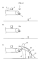
- FIGS. 2(a) to 2(c) show an embodiment of the separation method for the separation subject according to an implementation of the present invention and show the process of separating the desired first target 2 from the separation subject which is transported on the conveyor 1.
- the first target 2 is being transported on the conveyor 1 (conveyor belt).
- the first target 2 is passing under the information obtainment unit 3 so that the constituent substance and the shape are identified.
- a solid line, a single-dotted-dashed line, and a broken line indicate representative examples of a trajectory of the first target 2 being blown up, which has been discharged from the conveying end of the conveyor 1 and blown by the first airflow F1 in a pulse mode from the first blower 4 placed below the first drop path R1 of the first target 2 and thereby changed its drop trajectory (the trajectories indicated by these solid line, single-dotted-dashed line, and broken line include the second drop path R2).
- a shooting timing of the pulse airflow from the first blower 4 is controlled based on the information on constituent substance, shape, and position given from the information obtainment unit 3, and by striking the pulse airflow on the center of gravity of the first target 2, the first target 2 is made to travel on the trajectory indicated by the solid line so as to drop across the separation plate 5, thus being separated.
- Other pieces than the first targets 2 included in the separation subject are discharged from the conveying end of the conveyor 1 and then free-fall before the separation plate 5.
- the first airflow F1 generated in a pulse mode strikes the first target 2 not on the center of gravity but on a part (front edge part) lower than the center of gravity, the first target 2 travels on such a high trajectory as shown by the broken line and drops before the separation plate 5, thus failing to be separated.
- the second blower 6 capable of supplying the second airflow F2 in the same orientation as the running direction of the conveyor 1 and in the same direction as the first airflow F1
- the second drop path R2 of the first target 2 on a high trajectory is changed to the third drop path R3 (indicated by a double-dotted-dashed line in FIG. 2(c) ) so that the first target 2 drops across the separation plate, resulting in an increased recovery amount of the first targets 2.
- the first target 2 travels on a low trajectory as indicated by the sing le-dotted -dashed line, but does not fall before the separation plate and is thus able to be separated.
- Used refrigerators with compressors and thermal insulators from which chlorofluorocarbons had been removed were crushed by a crusher and collected as the separation subject 101.
- the separation subject 101 was then dispersed sequentially on the conveyor 1 (conveyor belt) running at 1 m/sec so that pieces in the separation subject 101 would not overlap one another.
- a near infrared distinguishing unit was used as a distinguishing unit of the information obtainment unit 3 to distinguish the ABS resin pieces in the separation subject 101 being transported on the conveyor 1.
- the ABS resin pieces discharged from the conveying end of the conveyor 1 were then blown by the first airflow F1 (having shooting pressure of 5 bar) in a pulse mode so as to fall across the separation plate 5, thus being separated.
- ABS resin pieces included in the separation subject 101 dropped before the separation plate 5 were distinguished using the near-infrared distinguishing unit to compare their weight with the weight of the ABS resin pieces dropped across the separation plate 5.
- a recovery ratio of the ABS included in the separation subject 101 was calculated.
- ABS recovery ratio was determined by A/(A+B) ⁇ 100.
- FIG. 3 shows a relationship between the recovery ratio of the ABS resin pieces and the blowing rate of the second airflow F2 which the second blower 6 placed above the drop path of the separation subject 101 supplies in the same orientation as the running direction of the conveyor 1.
- the height h of the second airflow F2 discharged in the same orientation as the running direction of the conveyor 1 is set to be 200 mm above a position in which the first airflow F1 strikes the ABS resin pieces.
- the recovery ratio of the ABS resin pieces improves along with an increase in the air blowing rate.
- the rate of the second airflow F2 was set in the range of 3 m/sec to 30 m/sec, the recovery ratio was 100%.
- the rate of the second airflow F2 was 50 m/sec or more, the recovery ratio of the ABS decreased, which revealed that when the air blowing rate is too high, this hinders the targets from being blown far.
- the blowing rate of the second airflow F2 be 3 m/sec to 30 m/sec.
- FIG. 4 shows a relationship between the recovery ratio of the ABS resin pieces and the discharge position h of the second airflow F2 that is supplied in the same orientation as the running direction of the conveyor 1.
- the discharge position h of the second airflow F2 is a distance vertically above the intersection of the first airflow F1 with the first drop path R1 of the separation subject 101.
- the blowing rate of air that is supplied in the same orientation as the running direction of the conveyor 1 was set to be 10 m/sec.
- the recovery ratio of the ABS resin pieces improves along with an increase in the height of the discharge position h.
- the recovery ratio was 100%.
- the recovery ratio of the ABS decreased. This is because even some of the ABS resin pieces which were struck on lower edges with the first airflow F1 drop before the separation plate 5 without being blown up to the height of 800 mm. This phenomenon was confirmed by the observation using a high-speed camera.
- the discharge position h of the air supplied in the same orientation as the running direction of the conveyor 1 be 80 mm to 700 mm.
- the present invention is applicable to resource recycling of materials as a separation method of recycling items of a specific constituent substance from electronic waste and general waste.
Landscapes
- Sorting Of Articles (AREA)
- Combined Means For Separation Of Solids (AREA)
Applications Claiming Priority (2)
| Application Number | Priority Date | Filing Date | Title |
|---|---|---|---|
| JP2009051351 | 2009-03-04 | ||
| PCT/JP2010/000227 WO2010100817A1 (fr) | 2009-03-04 | 2010-01-18 | Procédé de tri et dispositif de tri |
Publications (2)
| Publication Number | Publication Date |
|---|---|
| EP2241380A1 true EP2241380A1 (fr) | 2010-10-20 |
| EP2241380A4 EP2241380A4 (fr) | 2011-04-27 |
Family
ID=42709390
Family Applications (1)
| Application Number | Title | Priority Date | Filing Date |
|---|---|---|---|
| EP10742070A Withdrawn EP2241380A4 (fr) | 2009-03-04 | 2010-01-18 | Procédé de tri et dispositif de tri |
Country Status (5)
| Country | Link |
|---|---|
| US (1) | US8286800B2 (fr) |
| EP (1) | EP2241380A4 (fr) |
| JP (1) | JP5113907B2 (fr) |
| CN (1) | CN101952056A (fr) |
| WO (1) | WO2010100817A1 (fr) |
Cited By (1)
| Publication number | Priority date | Publication date | Assignee | Title |
|---|---|---|---|---|
| EP2907592A1 (fr) * | 2014-02-13 | 2015-08-19 | Buhler Sortex Ltd. | Appareil et procédé de tri |
Families Citing this family (12)
| Publication number | Priority date | Publication date | Assignee | Title |
|---|---|---|---|---|
| JP5052667B2 (ja) * | 2008-10-28 | 2012-10-17 | パナソニック株式会社 | 分別方法 |
| DE112012001499B4 (de) * | 2011-03-31 | 2019-12-05 | Mitsui Mining & Smelting Co., Ltd. | Tantalrückgewinnungsverfahren |
| EP2792424B1 (fr) * | 2011-12-15 | 2017-12-20 | Panasonic Intellectual Property Management Co., Ltd. | Dispositif de tri et procédé de tri |
| WO2013145872A1 (fr) * | 2012-03-28 | 2013-10-03 | 独立行政法人産業技術総合研究所 | Séparateur magnétique |
| CN102652942A (zh) * | 2012-03-29 | 2012-09-05 | 南京易北电气有限公司 | 一种新型多功能分料机 |
| JP5873989B2 (ja) * | 2013-04-25 | 2016-03-01 | パナソニックIpマネジメント株式会社 | 物質の選別装置、選別方法 |
| JP6098881B2 (ja) * | 2013-05-30 | 2017-03-22 | パナソニックIpマネジメント株式会社 | 選別装置 |
| USD1086366S1 (en) | 2015-07-06 | 2025-07-29 | Tomra Sorting Gmbh | Nozzle unit |
| USD1079893S1 (en) | 2016-07-06 | 2025-06-17 | Tomra Sorting Gmbh | Nozzle unit |
| EP3319732B1 (fr) * | 2015-07-06 | 2021-04-21 | TOMRA Sorting GmbH | Dispositif de buse et installation pour trier des objets |
| US9968942B2 (en) * | 2016-06-29 | 2018-05-15 | Boreal Compost Enterprises Ltd. | Method and apparatus for separating contaminants from compost and other recyclable materials |
| WO2022185341A1 (fr) * | 2021-03-04 | 2022-09-09 | Ishitva Robotic Systems Pvt Ltd | Unité de tri pneumatique |
Family Cites Families (12)
| Publication number | Priority date | Publication date | Assignee | Title |
|---|---|---|---|---|
| US5520290A (en) * | 1993-12-30 | 1996-05-28 | Huron Valley Steel Corporation | Scrap sorting system |
| US6060677A (en) * | 1994-08-19 | 2000-05-09 | Tiedemanns-Jon H. Andresen Ans | Determination of characteristics of material |
| US6266390B1 (en) * | 1998-09-21 | 2001-07-24 | Spectramet, Llc | High speed materials sorting using x-ray fluorescence |
| JP2000157936A (ja) * | 1998-11-27 | 2000-06-13 | Satake Eng Co Ltd | 粒状物選別方法及び粒状物選別装置 |
| ATE291969T1 (de) | 1999-04-30 | 2005-04-15 | Binder Co Ag | Verfahren und vorrichtung zum sortieren von altpapier |
| JP3467591B2 (ja) | 2001-03-08 | 2003-11-17 | 川崎重工業株式会社 | 廃プラスチックの選別方法及びその選別装置 |
| DE10123304A1 (de) * | 2001-05-14 | 2002-12-05 | Trienekens Ag | Vorrichtung und Verfahren zur Sortierung eines Abfallgemisches |
| JP3647799B2 (ja) * | 2001-12-03 | 2005-05-18 | 株式会社御池鐵工所 | 使用済みボトルの色別・材質別選別装置 |
| JP4023190B2 (ja) * | 2002-03-26 | 2007-12-19 | 株式会社Ihi | 光学式材質選別装置 |
| CA2647700C (fr) * | 2006-03-31 | 2012-12-11 | Thomas Valerio | Procede et dispositif de tri de metaux non ferreux fins et d'elements de fils metallique isoles |
| US7584856B2 (en) * | 2006-11-03 | 2009-09-08 | Emerging Acquisitions, Llc | Air separation of recyclable material |
| US7942273B2 (en) * | 2008-10-07 | 2011-05-17 | Emerging Acquisitions, Llc | Cross flow air separation system |
-
2010
- 2010-01-18 US US12/867,960 patent/US8286800B2/en not_active Expired - Fee Related
- 2010-01-18 JP JP2010521247A patent/JP5113907B2/ja not_active Expired - Fee Related
- 2010-01-18 CN CN2010800011171A patent/CN101952056A/zh active Pending
- 2010-01-18 WO PCT/JP2010/000227 patent/WO2010100817A1/fr not_active Ceased
- 2010-01-18 EP EP10742070A patent/EP2241380A4/fr not_active Withdrawn
Cited By (1)
| Publication number | Priority date | Publication date | Assignee | Title |
|---|---|---|---|---|
| EP2907592A1 (fr) * | 2014-02-13 | 2015-08-19 | Buhler Sortex Ltd. | Appareil et procédé de tri |
Also Published As
| Publication number | Publication date |
|---|---|
| US8286800B2 (en) | 2012-10-16 |
| JP5113907B2 (ja) | 2013-01-09 |
| EP2241380A4 (fr) | 2011-04-27 |
| WO2010100817A1 (fr) | 2010-09-10 |
| JPWO2010100817A1 (ja) | 2012-09-06 |
| CN101952056A (zh) | 2011-01-19 |
| US20110056874A1 (en) | 2011-03-10 |
Similar Documents
| Publication | Publication Date | Title |
|---|---|---|
| US8286800B2 (en) | Separation method and separation apparatus | |
| EP2792424B1 (fr) | Dispositif de tri et procédé de tri | |
| EP2808096A1 (fr) | Appareil et procédé de séparation | |
| AU2009291512B2 (en) | Sorting mined material | |
| EP2990129B1 (fr) | Dispositif et procédé de séparation du matériau | |
| US8201692B2 (en) | Materials separation module | |
| AU2009291513B2 (en) | Sorting mined material | |
| WO2013013276A1 (fr) | Tri de matériau extrait | |
| US20160175889A1 (en) | Separation apparatus | |
| US20130098807A1 (en) | Sorting mined material | |
| ZA200205504B (en) | Device and method for sorting out metal fractions from a stream of bulk material. | |
| CN111868275A (zh) | 电子电气设备部件废料的处理方法 | |
| JP2016215085A (ja) | 選別装置 | |
| WO2013149293A1 (fr) | Séparation de matériaux extraits d'une mine | |
| WO2010028448A1 (fr) | Tri de matière minière | |
| JP2011173049A (ja) | 分別方法、および、分別装置 | |
| EP2343136A1 (fr) | Procédé de tri | |
| JP7029333B2 (ja) | 電子・電気機器部品屑の処理方法 | |
| AU2012202226B2 (en) | Dissimilar materials sorting process, system and apparatus | |
| Julius et al. | Sensor based sorting in waste processing | |
| JP2019162620A (ja) | 電子・電気機器部品屑の処理方法 | |
| KR20240001110A (ko) | 재료 분리 시스템 |
Legal Events
| Date | Code | Title | Description |
|---|---|---|---|
| PUAI | Public reference made under article 153(3) epc to a published international application that has entered the european phase |
Free format text: ORIGINAL CODE: 0009012 |
|
| AK | Designated contracting states |
Kind code of ref document: A1 Designated state(s): AT BE BG CH CY CZ DE DK EE ES FI FR GB GR HR HU IE IS IT LI LT LU LV MC MK MT NL NO PL PT RO SE SI SK SM TR |
|
| AX | Request for extension of the european patent |
Extension state: AL BA RS |
|
| A4 | Supplementary search report drawn up and despatched |
Effective date: 20110325 |
|
| 17P | Request for examination filed |
Effective date: 20110606 |
|
| RBV | Designated contracting states (corrected) |
Designated state(s): AT BE BG CH CY CZ DE DK EE ES FI FR GB GR HR HU IE IS IT LI LT LU LV MC MK MT NL NO PL PT RO SE SI SK SM TR |
|
| DAX | Request for extension of the european patent (deleted) | ||
| 17Q | First examination report despatched |
Effective date: 20130712 |
|
| STAA | Information on the status of an ep patent application or granted ep patent |
Free format text: STATUS: THE APPLICATION IS DEEMED TO BE WITHDRAWN |
|
| 18D | Application deemed to be withdrawn |
Effective date: 20140211 |