EP2241792A2 - Double robinet-vanne - Google Patents
Double robinet-vanne Download PDFInfo
- Publication number
- EP2241792A2 EP2241792A2 EP20100156014 EP10156014A EP2241792A2 EP 2241792 A2 EP2241792 A2 EP 2241792A2 EP 20100156014 EP20100156014 EP 20100156014 EP 10156014 A EP10156014 A EP 10156014A EP 2241792 A2 EP2241792 A2 EP 2241792A2
- Authority
- EP
- European Patent Office
- Prior art keywords
- actuating rod
- locking
- slide
- locking nut
- closed position
- Prior art date
- Legal status (The legal status is an assumption and is not a legal conclusion. Google has not performed a legal analysis and makes no representation as to the accuracy of the status listed.)
- Granted
Links
Images



Classifications
-
- F—MECHANICAL ENGINEERING; LIGHTING; HEATING; WEAPONS; BLASTING
- F16—ENGINEERING ELEMENTS AND UNITS; GENERAL MEASURES FOR PRODUCING AND MAINTAINING EFFECTIVE FUNCTIONING OF MACHINES OR INSTALLATIONS; THERMAL INSULATION IN GENERAL
- F16K—VALVES; TAPS; COCKS; ACTUATING-FLOATS; DEVICES FOR VENTING OR AERATING
- F16K3/00—Gate valves or sliding valves, i.e. cut-off apparatus with closing members having a sliding movement along the seat for opening and closing
- F16K3/02—Gate valves or sliding valves, i.e. cut-off apparatus with closing members having a sliding movement along the seat for opening and closing with flat sealing faces; Packings therefor
- F16K3/16—Gate valves or sliding valves, i.e. cut-off apparatus with closing members having a sliding movement along the seat for opening and closing with flat sealing faces; Packings therefor with special arrangements for separating the sealing faces or for pressing them together
- F16K3/18—Gate valves or sliding valves, i.e. cut-off apparatus with closing members having a sliding movement along the seat for opening and closing with flat sealing faces; Packings therefor with special arrangements for separating the sealing faces or for pressing them together by movement of the closure members
- F16K3/184—Gate valves or sliding valves, i.e. cut-off apparatus with closing members having a sliding movement along the seat for opening and closing with flat sealing faces; Packings therefor with special arrangements for separating the sealing faces or for pressing them together by movement of the closure members by means of cams
- F16K3/186—Gate valves or sliding valves, i.e. cut-off apparatus with closing members having a sliding movement along the seat for opening and closing with flat sealing faces; Packings therefor with special arrangements for separating the sealing faces or for pressing them together by movement of the closure members by means of cams by means of cams of wedge from
-
- C—CHEMISTRY; METALLURGY
- C10—PETROLEUM, GAS OR COKE INDUSTRIES; TECHNICAL GASES CONTAINING CARBON MONOXIDE; FUELS; LUBRICANTS; PEAT
- C10B—DESTRUCTIVE DISTILLATION OF CARBONACEOUS MATERIALS FOR PRODUCTION OF GAS, COKE, TAR, OR SIMILAR MATERIALS
- C10B25/00—Doors or closures for coke ovens
- C10B25/02—Doors; Door frames
- C10B25/08—Closing and opening the doors
- C10B25/10—Closing and opening the doors for ovens with vertical chambers
-
- Y—GENERAL TAGGING OF NEW TECHNOLOGICAL DEVELOPMENTS; GENERAL TAGGING OF CROSS-SECTIONAL TECHNOLOGIES SPANNING OVER SEVERAL SECTIONS OF THE IPC; TECHNICAL SUBJECTS COVERED BY FORMER USPC CROSS-REFERENCE ART COLLECTIONS [XRACs] AND DIGESTS
- Y10—TECHNICAL SUBJECTS COVERED BY FORMER USPC
- Y10T—TECHNICAL SUBJECTS COVERED BY FORMER US CLASSIFICATION
- Y10T137/00—Fluid handling
- Y10T137/8158—With indicator, register, recorder, alarm or inspection means
- Y10T137/8225—Position or extent of motion indicator
- Y10T137/8242—Electrical
Definitions
- the present invention relates to a double plate slide whose shut-off plates are displaceable by an actuating rod from an open to a closed position and vice versa, wherein the actuating rod is associated with a locking means by means of which the slide plates together with the actuating rod can be fixed in the closed position.
- the slide plates With a firmly positioned locking the actuating rod for the slide plates, the slide plates can therefore not bring exactly in the optimal closed position with maximum sealing force. It must further be considered that the actuating rod after reaching the closed position again moves back a certain amount of up to 2 to 3 mm, namely so far, until the arranged on the actuating rod coupling piece bears against the locking wedge. This behavior involves the risk of leakage of the slider in the closed position.
- An essential aspect of the present invention is therefore that the locking device in the longitudinal direction of the actuating rod relative to this from a Unlocking in a locking position and vice versa is movable, wherein the locking position is variable according to the current closed position of the slider. Accordingly, the locking device adapts to the optimum locking position of the slide plates or the associated actuating rod. The locking position is therefore not firmly defined. This makes it possible to always perform the locking when the slide plates bear with a maximum predetermined contact force on the housing sealing seats.
- Another aspect of the present invention lies in the concrete construction of the locking device according to claims 2 to 6.
- Fig. 1 is a Doppelphttenschieber 10 according to the prior art, for example according to the EP 1 561 980 A1 shown in longitudinal section.
- This double plate slide has a slide housing 11 with an upper and a lower pipe socket 12, 13 and an upper and a lower housing sealing seat 14, 15, between which an upper and a lower shut-off or slide plate 16, 17 with an upper or a lower sealing ring 18, 19 is slidably mounted.
- the two slide plates 16, 17 are pressed against the housing sealing seats 14, 15 by means of acting as a spreading member inner wedge 20, which sits at the end of an actuating rod 21 and is firmly connected thereto.
- the slide plates 16, 17 are for this purpose by the inner wedge 20, which is centered by means of a ball, spreadable by a "wedge-in-wedge" principle. This design ensures that the slider is easy to operate even under the most severe thermal and dynamic conditions.
- a pipe bridge 22 is arranged, which has an upper and a lower sealing ring 23, 24.
- the pipe bridge 22 is formed as a hollow cylinder.
- plate spring assemblies 25 are arranged on the inside between the upper Genzousediclatsitz 14 and belonging to the upper pipe socket 12 supporting surface.
- the upper housing sealing seat 14 which is formed relative to the upper pipe socket 12 parallel to the extension direction or axially movable or displaceable, depending on the slide position against the peripheral edge of the upper slide plate 16 or the upper sealing ring 23 of the pipe bridge 22.
- the plate spring assemblies 25 are evenly distributed over the entire circumference of the upper housing sealing seat 14 and the upper pipe socket 12 to a safe closing function of the double plate slide 10 by a uniform pressing of the upper housing sealing seat 14 to the upper shut-off plate 16 and its sealing ring 18 (in the closed state of the slide) or to ensure the upper sealing ring 23 of the pipe bridge 22 (in slide-open position).
- Fig. 1 the slider is shown in the closed position.
- the slide housing 11 is formed fluid-tight to the outside, so that in the interior 27 of the valve body, a gas pressure is adjustable, which may also be greater than the pressure in the slide passage. For this reason, the actuating rod 21 extends in a fluid-tight manner into the slider housing 11.
- a compressed gas source in particular a rinsing and sealing vapor source
- the sealing surfaces of the sealing rings 23, 24 on the one hand and the Gescousedichtsitze 14, 15 on the other hand are each formed extending parallel to the slide actuating direction.
- the aforementioned parts are hardened or armored in a conventional manner. Through maintenance openings 30, it is possible, in particular to the pipe bridge 22 easy access for observation purposes u. to obtain.
- the maintenance openings 30 are in operation of the system in which the slide integrated is normally provided with blank flanges or housing covers so as to be able to act on the housing, as described above, with compressed gas or blocking or flushing steam.
- a coolant inlet 32 Via a coolant inlet 32, the actuating rod 21, in particular at its protruding from the housing end, to be cooled. This is preferably done by cold air or cold gases. At this point it should be mentioned that a liquid cooling is conceivable.
- the slide plates 16, 17 are in a spectacle-shaped plate cage (not shown in the figures), which ensures their holder, inserted movably. This plate cage is guided between guide plates 29, which prevents the ingress of contaminants into the housing.
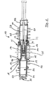
- the actuating rod 21 is preferably associated with a locking device with which the actuating rod can be locked in a fixed position, which is the closed position and, if necessary, also the opening position of the slider or the slide plates.
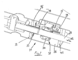
- This locking device which is designated by the reference numeral 31, comprises a arranged on the actuating rod 21 threaded portion, in particular trapezoidal threaded portion 33 on the one hand and a screwed onto this locking nut 34 on the other hand, the nut 34 in the closed position of the slider 10 on the threaded portion 33 to a fixed arranged opposite the actuating rod 21 stop 35 for locking the same can be screwed.
- the stop 35 is part of the slide housing 11, in the present case a drive rod 21 receiving drive column 36 which is fixedly connected to the slide housing 11.
- the locking nut 34 is by an electrical, pneumatic or - as here - hydraulic drive 37 on the threaded portion 33 of the actuating rod 21 up or unscrewed.
- the locking nut 34 is disposed within a parallel to the actuating rod 21 slidably mounted gear housing 38 and movable longitudinally with this.
- the gear housing 38 can be pressed by a helical compression spring 39 upon movement of the actuating rod 21 in the closed position against the threaded portion 33 on the actuating rod 21, so that the locking nut 34 controlled on the threaded portion 33 can be screwed.
- Coil springs 39 on the guide rods 40 determine the "front" position of the housing 38, in which threaded portion 33 and locking nut 34 meet.
- the coil springs 39 are each disposed between the transmission housing 38 and the slider housing 11 and an associated stop 41 within the drive column 36, as in Fig. 2 is shown.
- the hydraulic drive is first started.
- the locking nut 34 is unscrewed from the threaded portion 33.
- a measuring system receives the rotation of the locking nut and switches it off as soon as the locking nut and the associated gear housing are completely unscrewed from the threaded portion 33 again.
- the operating rod is now fully unlocked again and the slide can be opened again.
- lock nut and gear housing keep contact with the threaded portion 33 until the helical compression springs 39 are relaxed on the guide rods 40 again.
- lock nut 34 and gear housing 38 remain in position while the slider is opened further. It gets up to it Fig. 5 directed.
- the locking device then has the position again Fig. 2 ,
Landscapes
- Chemical & Material Sciences (AREA)
- Engineering & Computer Science (AREA)
- General Engineering & Computer Science (AREA)
- Materials Engineering (AREA)
- Oil, Petroleum & Natural Gas (AREA)
- Organic Chemistry (AREA)
- Mechanical Engineering (AREA)
- Sliding Valves (AREA)
- Multiple-Way Valves (AREA)
Priority Applications (1)
| Application Number | Priority Date | Filing Date | Title |
|---|---|---|---|
| PL10156014T PL2241792T3 (pl) | 2009-04-16 | 2010-03-10 | Dwupłytowy zawór zasuwowy |
Applications Claiming Priority (1)
| Application Number | Priority Date | Filing Date | Title |
|---|---|---|---|
| DE102009017634A DE102009017634A1 (de) | 2009-04-16 | 2009-04-16 | Doppelplattenschieber |
Publications (3)
| Publication Number | Publication Date |
|---|---|
| EP2241792A2 true EP2241792A2 (fr) | 2010-10-20 |
| EP2241792A3 EP2241792A3 (fr) | 2014-04-23 |
| EP2241792B1 EP2241792B1 (fr) | 2015-11-25 |
Family
ID=42342726
Family Applications (1)
| Application Number | Title | Priority Date | Filing Date |
|---|---|---|---|
| EP10156014.2A Active EP2241792B1 (fr) | 2009-04-16 | 2010-03-10 | Double robinet-vanne |
Country Status (4)
| Country | Link |
|---|---|
| US (1) | US8413956B2 (fr) |
| EP (1) | EP2241792B1 (fr) |
| DE (1) | DE102009017634A1 (fr) |
| PL (1) | PL2241792T3 (fr) |
Cited By (3)
| Publication number | Priority date | Publication date | Assignee | Title |
|---|---|---|---|---|
| DE202016102555U1 (de) | 2016-04-19 | 2016-06-10 | Z & J Technologies Gmbh | Absperrorgan für eine Ethylenherstellungsanlage und Ethylenherstellungsanlage |
| DE202016102554U1 (de) | 2016-01-29 | 2016-06-21 | Z & J Technologies Gmbh | Doppelplattenschieber für eine Ethylenanlage und Ethylenanlage |
| EP3743644A1 (fr) * | 2018-01-23 | 2020-12-02 | Z & J Technologies GmbH | Distributeur à tiroir et utilisation d'un distributeur à tiroir |
Families Citing this family (3)
| Publication number | Priority date | Publication date | Assignee | Title |
|---|---|---|---|---|
| DE102012101015B4 (de) * | 2012-02-08 | 2013-09-05 | Z & J Technologies Gmbh | Verkokungstrommel, Absperrventil für eine Verkokungstrommel und Verfahren zum Zuführen von Reststoffen in eine Verkokungstrommel |
| CN108757973B (zh) * | 2018-08-16 | 2023-11-14 | 北京航天石化技术装备工程有限公司 | 一种双闸板闸阀 |
| US11280412B2 (en) * | 2019-01-14 | 2022-03-22 | Mpr Associates, Inc. | Stem anti-rotation device for nuclear reactor power plant gate valves and maintenance method using the stem anti-rotation device |
Citations (3)
| Publication number | Priority date | Publication date | Assignee | Title |
|---|---|---|---|---|
| EP0450646A2 (fr) | 1990-04-06 | 1991-10-09 | Zimmermann & Jansen GmbH | Vanne à tiroir composé de deux plaques |
| WO1998017934A1 (fr) | 1996-10-23 | 1998-04-30 | Zimmermann & Jansen Gmbh | Coulisse, en particulier coulisse a pont tubulaire |
| EP1561980A1 (fr) | 2004-02-04 | 2005-08-10 | Z&J Technologies GmbH | Vanne à tiroir composé de deux plaques |
Family Cites Families (11)
| Publication number | Priority date | Publication date | Assignee | Title |
|---|---|---|---|---|
| US2843152A (en) * | 1954-12-01 | 1958-07-15 | Crane Co | Combined valve actuating and locking means |
| NL133568C (fr) * | 1966-07-01 | |||
| US4168137A (en) * | 1978-03-08 | 1979-09-18 | The Upjohn Company | Triaxial tablet compressor machine |
| DE3333061C2 (de) * | 1983-09-14 | 1985-08-01 | Carl Heinz Dipl.-Ing. 4050 Mönchengladbach Häfele | Einstellbare Verriegelung für drehende Antriebe, insbesondere an Armaturen wie Ventile, Schieber oder dergleichen |
| JP2574449B2 (ja) * | 1989-02-17 | 1997-01-22 | 株式会社巴技術研究所 | バタフライ弁 |
| DE4117577A1 (de) * | 1991-05-29 | 1992-12-03 | Sempell Babcock Ag | Plattenschieber |
| US5220843A (en) * | 1991-07-26 | 1993-06-22 | Portland General Electric Corporation | In situ method of determining the thrust on valve components |
| US6044860A (en) * | 1999-02-01 | 2000-04-04 | Spx Corporation | Adjustable lockout device for knife gate valves |
| DE102005014214A1 (de) * | 2005-03-29 | 2006-10-05 | Z & J Technologies Gmbh | Schieber, insbesondere Doppelplattenschieber |
| GB0613662D0 (en) * | 2006-07-10 | 2006-08-16 | Rotork Controls | Improvements to valve actuators |
| US20110083746A1 (en) * | 2009-10-09 | 2011-04-14 | Cameron International Corporation | Smart valve utilizing a force sensor |
-
2009
- 2009-04-16 DE DE102009017634A patent/DE102009017634A1/de not_active Withdrawn
-
2010
- 2010-01-22 US US12/692,119 patent/US8413956B2/en active Active
- 2010-03-10 EP EP10156014.2A patent/EP2241792B1/fr active Active
- 2010-03-10 PL PL10156014T patent/PL2241792T3/pl unknown
Patent Citations (3)
| Publication number | Priority date | Publication date | Assignee | Title |
|---|---|---|---|---|
| EP0450646A2 (fr) | 1990-04-06 | 1991-10-09 | Zimmermann & Jansen GmbH | Vanne à tiroir composé de deux plaques |
| WO1998017934A1 (fr) | 1996-10-23 | 1998-04-30 | Zimmermann & Jansen Gmbh | Coulisse, en particulier coulisse a pont tubulaire |
| EP1561980A1 (fr) | 2004-02-04 | 2005-08-10 | Z&J Technologies GmbH | Vanne à tiroir composé de deux plaques |
Cited By (8)
| Publication number | Priority date | Publication date | Assignee | Title |
|---|---|---|---|---|
| DE202016102554U1 (de) | 2016-01-29 | 2016-06-21 | Z & J Technologies Gmbh | Doppelplattenschieber für eine Ethylenanlage und Ethylenanlage |
| DE102016101627A1 (de) | 2016-01-29 | 2017-08-03 | Z & J Technologies Gmbh | Doppelplattenschieber für eine Ethylenanlage, Ethylenanlage und Verfahren zum Betrieb einer Ethylenanlage |
| DE102016101627B4 (de) | 2016-01-29 | 2023-01-19 | Z & J Technologies Gmbh | Doppelplattenschieber für eine Ethylenanlage, Ethylenanlage und Verfahren zum Betrieb einer Ethylenanlage |
| DE202016102555U1 (de) | 2016-04-19 | 2016-06-10 | Z & J Technologies Gmbh | Absperrorgan für eine Ethylenherstellungsanlage und Ethylenherstellungsanlage |
| DE102016107175A1 (de) | 2016-04-19 | 2017-10-19 | Z & J Technologies Gmbh | Absperrorgan für eine Ethylenherstellungsanlage, Ethylenherstellungsanlage und Verfahren zum Betrieb einer Ethylenherstellungsanlage |
| DE102016107175B4 (de) | 2016-04-19 | 2025-02-06 | Z & J Technologies Gmbh | Absperrorgan für eine Ethylenherstellungsanlage |
| EP3743644A1 (fr) * | 2018-01-23 | 2020-12-02 | Z & J Technologies GmbH | Distributeur à tiroir et utilisation d'un distributeur à tiroir |
| US11920692B2 (en) | 2018-01-23 | 2024-03-05 | Z & J Technologies Gmbh | Slide valve and use of a slide valve |
Also Published As
| Publication number | Publication date |
|---|---|
| EP2241792B1 (fr) | 2015-11-25 |
| EP2241792A3 (fr) | 2014-04-23 |
| PL2241792T3 (pl) | 2016-06-30 |
| DE102009017634A1 (de) | 2011-03-31 |
| US8413956B2 (en) | 2013-04-09 |
| US20100264349A1 (en) | 2010-10-21 |
Similar Documents
| Publication | Publication Date | Title |
|---|---|---|
| EP2241792B1 (fr) | Double robinet-vanne | |
| EP2177796B1 (fr) | Dispositif de soupape tubulaire | |
| EP2547927B1 (fr) | Ensemble capteur pour un frein à disque | |
| EP1561980B1 (fr) | Vanne à tiroir composé de deux plaques | |
| EP0320491A2 (fr) | Elément de fermeture pour tuyauterie | |
| EP3362699B1 (fr) | Dispositif de surveillance pour frein à disque d'un véhicule automobile | |
| DE29623103U1 (de) | Schieber, insbesondere Rohrbrückenschieber | |
| EP2986876B1 (fr) | Vanne de sécurité antidéflagrante | |
| DE102016214683A1 (de) | Sperranordnung | |
| DE102021204093A1 (de) | Ventileinrichtung mit Niederhalter | |
| EP3546117B1 (fr) | Module de serrage, en particulier module de serrage au point zéro | |
| DE102012209031A1 (de) | Absperrschieber | |
| DE102011050263B4 (de) | Ventilvorrichtung für eine Verbrennungskraftmaschine | |
| DE19723962C2 (de) | Doppelplattenschieber | |
| DE2736708A1 (de) | Zweiplatten-schieber | |
| DE102018100519A1 (de) | Ventilantrieb mit Schnellfahrfunktion | |
| AT516355A1 (de) | Ausrückzylinder zum betätigen eines reibungselementes | |
| EP3728821B1 (fr) | Dispositif de vanne pour un moteur à combustion interne | |
| EP4194713B1 (fr) | Frein multidisque pour véhicule automobile | |
| DE29912784U1 (de) | Sitzventil | |
| DE102010049892B4 (de) | Vorrichtung zum Betätigen eines Schließelements einer Armatur | |
| EP2189691B1 (fr) | Armature de verrouillage pour un système de conduite | |
| DE1919864C (de) | Abnehmbare Leckauffangvornchtung fur ein Verschluß ventil fur Brenn stoffkanale von Atomkernreaktoren | |
| EP1793113B1 (fr) | Vanne double pour dispositif de recyclage des gaz d'échappement | |
| DE4406207A1 (de) | Antriebseinheit |
Legal Events
| Date | Code | Title | Description |
|---|---|---|---|
| PUAI | Public reference made under article 153(3) epc to a published international application that has entered the european phase |
Free format text: ORIGINAL CODE: 0009012 |
|
| AK | Designated contracting states |
Kind code of ref document: A2 Designated state(s): AT BE BG CH CY CZ DE DK EE ES FI FR GB GR HR HU IE IS IT LI LT LU LV MC MK MT NL NO PL PT RO SE SI SK SM TR |
|
| AX | Request for extension of the european patent |
Extension state: AL BA ME RS |
|
| PUAL | Search report despatched |
Free format text: ORIGINAL CODE: 0009013 |
|
| AK | Designated contracting states |
Kind code of ref document: A3 Designated state(s): AT BE BG CH CY CZ DE DK EE ES FI FR GB GR HR HU IE IS IT LI LT LU LV MC MK MT NL NO PL PT RO SE SI SK SM TR |
|
| AX | Request for extension of the european patent |
Extension state: AL BA ME RS |
|
| RIC1 | Information provided on ipc code assigned before grant |
Ipc: F16K 3/18 20060101AFI20140319BHEP |
|
| 17P | Request for examination filed |
Effective date: 20140709 |
|
| RBV | Designated contracting states (corrected) |
Designated state(s): AT BE BG CH CY CZ DE DK EE ES FI FR GB GR HR HU IE IS IT LI LT LU LV MC MK MT NL NO PL PT RO SE SI SK SM TR |
|
| 17Q | First examination report despatched |
Effective date: 20141030 |
|
| GRAP | Despatch of communication of intention to grant a patent |
Free format text: ORIGINAL CODE: EPIDOSNIGR1 |
|
| INTG | Intention to grant announced |
Effective date: 20150609 |
|
| GRAS | Grant fee paid |
Free format text: ORIGINAL CODE: EPIDOSNIGR3 |
|
| GRAA | (expected) grant |
Free format text: ORIGINAL CODE: 0009210 |
|
| AK | Designated contracting states |
Kind code of ref document: B1 Designated state(s): AT BE BG CH CY CZ DE DK EE ES FI FR GB GR HR HU IE IS IT LI LT LU LV MC MK MT NL NO PL PT RO SE SI SK SM TR |
|
| REG | Reference to a national code |
Ref country code: GB Ref legal event code: FG4D Free format text: NOT ENGLISH |
|
| REG | Reference to a national code |
Ref country code: CH Ref legal event code: EP |
|
| REG | Reference to a national code |
Ref country code: AT Ref legal event code: REF Ref document number: 762799 Country of ref document: AT Kind code of ref document: T Effective date: 20151215 |
|
| REG | Reference to a national code |
Ref country code: IE Ref legal event code: FG4D Free format text: LANGUAGE OF EP DOCUMENT: GERMAN |
|
| REG | Reference to a national code |
Ref country code: DE Ref legal event code: R096 Ref document number: 502010010679 Country of ref document: DE |
|
| REG | Reference to a national code |
Ref country code: LT Ref legal event code: MG4D |
|
| REG | Reference to a national code |
Ref country code: NL Ref legal event code: MP Effective date: 20160225 |
|
| PG25 | Lapsed in a contracting state [announced via postgrant information from national office to epo] |
Ref country code: IS Free format text: LAPSE BECAUSE OF FAILURE TO SUBMIT A TRANSLATION OF THE DESCRIPTION OR TO PAY THE FEE WITHIN THE PRESCRIBED TIME-LIMIT Effective date: 20160325 Ref country code: NL Free format text: LAPSE BECAUSE OF FAILURE TO SUBMIT A TRANSLATION OF THE DESCRIPTION OR TO PAY THE FEE WITHIN THE PRESCRIBED TIME-LIMIT Effective date: 20151125 Ref country code: LT Free format text: LAPSE BECAUSE OF FAILURE TO SUBMIT A TRANSLATION OF THE DESCRIPTION OR TO PAY THE FEE WITHIN THE PRESCRIBED TIME-LIMIT Effective date: 20151125 Ref country code: HR Free format text: LAPSE BECAUSE OF FAILURE TO SUBMIT A TRANSLATION OF THE DESCRIPTION OR TO PAY THE FEE WITHIN THE PRESCRIBED TIME-LIMIT Effective date: 20151125 Ref country code: NO Free format text: LAPSE BECAUSE OF FAILURE TO SUBMIT A TRANSLATION OF THE DESCRIPTION OR TO PAY THE FEE WITHIN THE PRESCRIBED TIME-LIMIT Effective date: 20160225 Ref country code: ES Free format text: LAPSE BECAUSE OF FAILURE TO SUBMIT A TRANSLATION OF THE DESCRIPTION OR TO PAY THE FEE WITHIN THE PRESCRIBED TIME-LIMIT Effective date: 20151125 |
|
| PG25 | Lapsed in a contracting state [announced via postgrant information from national office to epo] |
Ref country code: PT Free format text: LAPSE BECAUSE OF FAILURE TO SUBMIT A TRANSLATION OF THE DESCRIPTION OR TO PAY THE FEE WITHIN THE PRESCRIBED TIME-LIMIT Effective date: 20160325 Ref country code: LV Free format text: LAPSE BECAUSE OF FAILURE TO SUBMIT A TRANSLATION OF THE DESCRIPTION OR TO PAY THE FEE WITHIN THE PRESCRIBED TIME-LIMIT Effective date: 20151125 Ref country code: SE Free format text: LAPSE BECAUSE OF FAILURE TO SUBMIT A TRANSLATION OF THE DESCRIPTION OR TO PAY THE FEE WITHIN THE PRESCRIBED TIME-LIMIT Effective date: 20151125 Ref country code: GR Free format text: LAPSE BECAUSE OF FAILURE TO SUBMIT A TRANSLATION OF THE DESCRIPTION OR TO PAY THE FEE WITHIN THE PRESCRIBED TIME-LIMIT Effective date: 20160226 Ref country code: FI Free format text: LAPSE BECAUSE OF FAILURE TO SUBMIT A TRANSLATION OF THE DESCRIPTION OR TO PAY THE FEE WITHIN THE PRESCRIBED TIME-LIMIT Effective date: 20151125 |
|
| RAP2 | Party data changed (patent owner data changed or rights of a patent transferred) |
Owner name: Z & J TECHNOLOGIES GMBH |
|
| PG25 | Lapsed in a contracting state [announced via postgrant information from national office to epo] |
Ref country code: IT Free format text: LAPSE BECAUSE OF FAILURE TO SUBMIT A TRANSLATION OF THE DESCRIPTION OR TO PAY THE FEE WITHIN THE PRESCRIBED TIME-LIMIT Effective date: 20151125 Ref country code: CZ Free format text: LAPSE BECAUSE OF FAILURE TO SUBMIT A TRANSLATION OF THE DESCRIPTION OR TO PAY THE FEE WITHIN THE PRESCRIBED TIME-LIMIT Effective date: 20151125 |
|
| REG | Reference to a national code |
Ref country code: DE Ref legal event code: R097 Ref document number: 502010010679 Country of ref document: DE |
|
| PG25 | Lapsed in a contracting state [announced via postgrant information from national office to epo] |
Ref country code: SK Free format text: LAPSE BECAUSE OF FAILURE TO SUBMIT A TRANSLATION OF THE DESCRIPTION OR TO PAY THE FEE WITHIN THE PRESCRIBED TIME-LIMIT Effective date: 20151125 Ref country code: EE Free format text: LAPSE BECAUSE OF FAILURE TO SUBMIT A TRANSLATION OF THE DESCRIPTION OR TO PAY THE FEE WITHIN THE PRESCRIBED TIME-LIMIT Effective date: 20151125 Ref country code: SM Free format text: LAPSE BECAUSE OF FAILURE TO SUBMIT A TRANSLATION OF THE DESCRIPTION OR TO PAY THE FEE WITHIN THE PRESCRIBED TIME-LIMIT Effective date: 20151125 Ref country code: RO Free format text: LAPSE BECAUSE OF FAILURE TO SUBMIT A TRANSLATION OF THE DESCRIPTION OR TO PAY THE FEE WITHIN THE PRESCRIBED TIME-LIMIT Effective date: 20151125 Ref country code: DK Free format text: LAPSE BECAUSE OF FAILURE TO SUBMIT A TRANSLATION OF THE DESCRIPTION OR TO PAY THE FEE WITHIN THE PRESCRIBED TIME-LIMIT Effective date: 20151125 Ref country code: BE Free format text: LAPSE BECAUSE OF NON-PAYMENT OF DUE FEES Effective date: 20160331 |
|
| PLBE | No opposition filed within time limit |
Free format text: ORIGINAL CODE: 0009261 |
|
| STAA | Information on the status of an ep patent application or granted ep patent |
Free format text: STATUS: NO OPPOSITION FILED WITHIN TIME LIMIT |
|
| PG25 | Lapsed in a contracting state [announced via postgrant information from national office to epo] |
Ref country code: MC Free format text: LAPSE BECAUSE OF FAILURE TO SUBMIT A TRANSLATION OF THE DESCRIPTION OR TO PAY THE FEE WITHIN THE PRESCRIBED TIME-LIMIT Effective date: 20151125 Ref country code: LU Free format text: LAPSE BECAUSE OF FAILURE TO SUBMIT A TRANSLATION OF THE DESCRIPTION OR TO PAY THE FEE WITHIN THE PRESCRIBED TIME-LIMIT Effective date: 20160310 |
|
| REG | Reference to a national code |
Ref country code: CH Ref legal event code: PL |
|
| 26N | No opposition filed |
Effective date: 20160826 |
|
| GBPC | Gb: european patent ceased through non-payment of renewal fee |
Effective date: 20160310 |
|
| PG25 | Lapsed in a contracting state [announced via postgrant information from national office to epo] |
Ref country code: SI Free format text: LAPSE BECAUSE OF FAILURE TO SUBMIT A TRANSLATION OF THE DESCRIPTION OR TO PAY THE FEE WITHIN THE PRESCRIBED TIME-LIMIT Effective date: 20151125 |
|
| REG | Reference to a national code |
Ref country code: IE Ref legal event code: MM4A |
|
| REG | Reference to a national code |
Ref country code: FR Ref legal event code: ST Effective date: 20161130 |
|
| PG25 | Lapsed in a contracting state [announced via postgrant information from national office to epo] |
Ref country code: LI Free format text: LAPSE BECAUSE OF NON-PAYMENT OF DUE FEES Effective date: 20160331 Ref country code: CH Free format text: LAPSE BECAUSE OF NON-PAYMENT OF DUE FEES Effective date: 20160331 Ref country code: FR Free format text: LAPSE BECAUSE OF NON-PAYMENT OF DUE FEES Effective date: 20160331 Ref country code: GB Free format text: LAPSE BECAUSE OF NON-PAYMENT OF DUE FEES Effective date: 20160310 Ref country code: IE Free format text: LAPSE BECAUSE OF NON-PAYMENT OF DUE FEES Effective date: 20160310 |
|
| REG | Reference to a national code |
Ref country code: AT Ref legal event code: MM01 Ref document number: 762799 Country of ref document: AT Kind code of ref document: T Effective date: 20160310 |
|
| PG25 | Lapsed in a contracting state [announced via postgrant information from national office to epo] |
Ref country code: MT Free format text: LAPSE BECAUSE OF FAILURE TO SUBMIT A TRANSLATION OF THE DESCRIPTION OR TO PAY THE FEE WITHIN THE PRESCRIBED TIME-LIMIT Effective date: 20151125 Ref country code: AT Free format text: LAPSE BECAUSE OF NON-PAYMENT OF DUE FEES Effective date: 20160310 |
|
| PG25 | Lapsed in a contracting state [announced via postgrant information from national office to epo] |
Ref country code: HU Free format text: LAPSE BECAUSE OF FAILURE TO SUBMIT A TRANSLATION OF THE DESCRIPTION OR TO PAY THE FEE WITHIN THE PRESCRIBED TIME-LIMIT; INVALID AB INITIO Effective date: 20100310 Ref country code: CY Free format text: LAPSE BECAUSE OF FAILURE TO SUBMIT A TRANSLATION OF THE DESCRIPTION OR TO PAY THE FEE WITHIN THE PRESCRIBED TIME-LIMIT Effective date: 20151125 |
|
| PG25 | Lapsed in a contracting state [announced via postgrant information from national office to epo] |
Ref country code: TR Free format text: LAPSE BECAUSE OF FAILURE TO SUBMIT A TRANSLATION OF THE DESCRIPTION OR TO PAY THE FEE WITHIN THE PRESCRIBED TIME-LIMIT Effective date: 20151125 Ref country code: MK Free format text: LAPSE BECAUSE OF FAILURE TO SUBMIT A TRANSLATION OF THE DESCRIPTION OR TO PAY THE FEE WITHIN THE PRESCRIBED TIME-LIMIT Effective date: 20151125 |
|
| PG25 | Lapsed in a contracting state [announced via postgrant information from national office to epo] |
Ref country code: BG Free format text: LAPSE BECAUSE OF FAILURE TO SUBMIT A TRANSLATION OF THE DESCRIPTION OR TO PAY THE FEE WITHIN THE PRESCRIBED TIME-LIMIT Effective date: 20151125 |
|
| PGFP | Annual fee paid to national office [announced via postgrant information from national office to epo] |
Ref country code: DE Payment date: 20250331 Year of fee payment: 16 |
|
| PGFP | Annual fee paid to national office [announced via postgrant information from national office to epo] |
Ref country code: PL Payment date: 20260212 Year of fee payment: 17 |