EP2241865A1 - Positive displacement flowmeter - Google Patents
Positive displacement flowmeter Download PDFInfo
- Publication number
- EP2241865A1 EP2241865A1 EP08721439A EP08721439A EP2241865A1 EP 2241865 A1 EP2241865 A1 EP 2241865A1 EP 08721439 A EP08721439 A EP 08721439A EP 08721439 A EP08721439 A EP 08721439A EP 2241865 A1 EP2241865 A1 EP 2241865A1
- Authority
- EP
- European Patent Office
- Prior art keywords
- positive displacement
- pair
- displacement flowmeter
- curve
- rotor
- Prior art date
- Legal status (The legal status is an assumption and is not a legal conclusion. Google has not performed a legal analysis and makes no representation as to the accuracy of the status listed.)
- Withdrawn
Links
- 238000006073 displacement reaction Methods 0.000 title claims abstract description 23
- 238000005096 rolling process Methods 0.000 abstract description 10
- 238000010586 diagram Methods 0.000 description 9
- 230000007704 transition Effects 0.000 description 6
- 230000002159 abnormal effect Effects 0.000 description 4
- 239000012530 fluid Substances 0.000 description 3
- 238000005299 abrasion Methods 0.000 description 2
- 230000005540 biological transmission Effects 0.000 description 2
- 230000033001 locomotion Effects 0.000 description 2
- 238000004088 simulation Methods 0.000 description 2
- 230000006866 deterioration Effects 0.000 description 1
- 230000000694 effects Effects 0.000 description 1
- 238000004519 manufacturing process Methods 0.000 description 1
Images


Classifications
-
- G—PHYSICS
- G01—MEASURING; TESTING
- G01F—MEASURING VOLUME, VOLUME FLOW, MASS FLOW OR LIQUID LEVEL; METERING BY VOLUME
- G01F3/00—Measuring the volume flow of fluids or fluent solid material wherein the fluid passes through the meter in successive and more or less isolated quantities, the meter being driven by the flow
- G01F3/02—Measuring the volume flow of fluids or fluent solid material wherein the fluid passes through the meter in successive and more or less isolated quantities, the meter being driven by the flow with measuring chambers which expand or contract during measurement
- G01F3/04—Measuring the volume flow of fluids or fluent solid material wherein the fluid passes through the meter in successive and more or less isolated quantities, the meter being driven by the flow with measuring chambers which expand or contract during measurement having rigid movable walls
- G01F3/06—Measuring the volume flow of fluids or fluent solid material wherein the fluid passes through the meter in successive and more or less isolated quantities, the meter being driven by the flow with measuring chambers which expand or contract during measurement having rigid movable walls comprising members rotating in a fluid-tight or substantially fluid-tight manner in a housing
- G01F3/10—Geared or lobed impeller meters
Definitions
- the present invention relates to a positive displacement flowmeter and, more particularly, to a positive displacement flowmeter using a pitch curve itself of non-circular gears as a rotor tooth profile.
- a locus of a contact point of external gear tooth profiles making continuous contact generally forms a lemniscate loop curve and if this loop is flattened toward a center line between axes and coincides with the center line, the contact point moves on the center of both gears. Therefore, the tooth profile has a contour that achieves rolling motion, which corresponds to a pitch curve of non-uniform speed gear (non-circular gear).
- a contour of a rolling contact wheel which has a constant center distance and an angular velocity ratio that varies during rotation is a non-circular curve and a non-circular gear is a gear provided with teeth using this non-circular curve as a pitch curve to ensure transmission.
- a transmissible tooth profile is generally provided on the pitch curve. This tooth profile may be involute, cycloidal/ trochoidal, Novikov, or a combination thereof, each of which has drawback and advantage.
- a helical gear positive displacement flowmeter described in Patent Document 1 uses a single-point continuous contact tooth profile of a single curve.
- the single-point continuous contact tooth profile is ideal for a rotor tooth profile of a flowmeter since higher surface pressure bearing strength is expected due to convex/concave contact of tooth surfaces and no trapping phenomenon occurs which is disadvantageous to a flowmeter.
- the single-point continuous contact tooth profile represented by a sine-curve gear has a helical shape due to a contact ratio and the tooth height ratio is limited to 0.785 m, i.e., nm/4 (m: module) if formed by a single curve. This is disadvantageous to a rotor of a flowmeter in aspect of function or production.
- a pitch curve of a non-circular gear is considered as an ideal tooth profile curve that enables the continuous contact and the rolling contact instead of slide contact between tooth profiles as a gear tooth profile. It is assumed that a tooth profile of a flowmeter rotor is formed by a pitch curve (rolling-contact curve) of an oval gear that is a type of non-circular gears. In this case, it is known that the tooth profile does not act as a gear since a tooth profile for certainly transmitting the rotation is not included.
- Patent Document 1 Japanese Patent Publication No. 3310239
- the present invention was conceived in view of the above situations and it is therefore the object of the present invention to provide a positive displacement flowmeter having a pair of non-circular gears making rolling contact without slip on a pitch line.
- a second technical means is the first technical means wherein the pair of the non-circular gears has a spur shape.
- a third technical means is the first or second technical means wherein when the pair of the non-circular gears is in an engaged state at an equivalent radius position, a gap is provided between tooth shapes on long radius side of one of the non-circular gears and short radius side of the other non-circular gear.
- a fourth technical means is any one of the first to third technical means wherein the pair of the non-circular gears is made up of the same shaped non-circular gears.
- abrasion resistance is achieved since a pair of non-circular gears of a positive displacement flowmeter makes rolling contact without slip on a pitch line; a higher torque efficiency is achieved since a larger value can be given to a tooth height ratio; and it is possible to form the gears in spur shape instead of helical shape while avoiding abnormal engagement since apparent backlash is provided.
- Fig. 1 is a diagram of an exemplary configuration of a positive displacement flowmeter according to one embodiment of the present invention.
- 1 and 2 denote a pair of rotors; 3 denotes a casing; 4 an 5 denote axial centers of the rotors 1 and 2, respectively; 6 denotes a virtual pitch circle of the rotor 1; 7 denotes a virtual pitch circle of the rotor 2; 8 denotes an addendum circle of the rotor 1; and 9 denotes an addendum circle of the rotor 2.
- a pair of the rotors 1, 2 is housed in the casing 3 of the positive displacement flowmeter rotatably around the axial centers 4, 5.
- the moving radius is represented by the following Eq. (1) for the oval pitch curve that is a rolling contact curve (closed curve), where a, b, n and ⁇ i denote a homothetic coefficient, a flattening, a number of lobes, and a moving angle, respectively.
- a long radius r L and a short radius r S are represented by the following Eq.(2) and Eq.(3).
- the second interference is interference generated by substantial portions of tooth shapes with each other at an irrelevant position other than the contact point P in the course of movement of the contact point P along a given locus.
- K a center distance between the axial centers 4 and 5
- the flattening b is set to 0.5
- the homothetic coefficient a is obtained as 3.75 from the following Eq. (4).
- a K ⁇ 1 - b 2 / 2
- the torque is greater in the right rotor 2 than the left rotor 1 in the state of Fig. 1 and, therefore, the right rotor 2 acts as the driving side to rotate the left rotor 1 in the direction of arrows in Fig. 1 .
- Fig. 2(B) is an enlarged diagram of an X portion of Fig. 2(A) .
- the torques of the rotors 1, 2 become equivalent and the left rotor 1 is instantaneously switched to the driving side from this state.
- the transition of the engagement state is depicted when the rotors 1, 2 rotate from 0° to 30° in the order of Fig. 3(A) to Fig. 3(F) .
- P denotes the contact point of the rotors 1, 2
- t denotes the apparent backlash between the rotors 1, 2.
- the rotors 1 and 2 are housed in the casing 3 rotatably around the axial centers 4 and 5, the casing 3 is not illustrated.
- Fig. 3(A) shows the case when the angle ⁇ 1 of the rotor 1 is 0° and the angle ⁇ 2 of the rotor 2 is ⁇ °
- Fig. 3(B) shows the case when the angle ⁇ 1 of the rotor 1 is 10.00° and the angle ⁇ 2 of the rotor 2 is 20.00°
- Fig. 3(C) shows the case when the angle ⁇ 1 of the rotor 1 is 15.00° and the angle ⁇ 2 of the rotor 2 is 23.86°.
- Fig. 3(D) shows the case when the angle ⁇ 1 of the rotor 1 is 18.00° and the angle ⁇ 2 of the rotor 2 is 25.46°; Fig. 3(E) shows the case when the angle ⁇ 1 of the rotor 1 is 24.00° and the angle ⁇ 2 of the rotor 2 is 27.94°; and Fig. 3(F) shows the case when the angle ⁇ 1 of the rotor 1 is 30.00° and the angle ⁇ 2 of the rotor 2 is 30.00°.
- the apparent backlash t is minimized and the measured value thereof is about 0.07 mm.
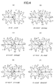
- the present invention may be implemented by appropriately setting the flattening b even when the number of lobes n is 8.
- the flattening b is set to 0.34.
- the measured value of the apparent backlash t in this case is about 0.02 mm (minimum value).
- the transition of the engagement state is depicted when the rotors 1, 2 rotate from 0° to 22.5° in the order of Fig. 4(A) to Fig. 4(F) .
- P denotes the contact point of the rotors 1, 2
- t denotes the apparent backlash between the rotors 1, 2.
- the rotors 1 and 2 are housed in the casing 3 rotatably around the axial centers 4 and 5, the casing 3 is not illustrated.
- Fig. 4(A) shows the case when the angle ⁇ 1 of the rotor 1 is 0° and the angle ⁇ 2 of the rotor 2 is 0°;
- Fig. 4(B) shows the case when the angle ⁇ 1 of the rotor 1 is 10.53° and the angle ⁇ 2 of the rotor 2 is 6.00°;
- Fig. 4(C) shows the case when the angle ⁇ 1 of the rotor 1 is 13.97° and the angle ⁇ 2 of the rotor 2 is 9.00°.
- Fig. 4(D) shows the case when the angle ⁇ 1 of the rotor 1 is 18.53° and the angle ⁇ 2 of the rotor 2 is 15.00°; Fig. 4(E) shows the case when the angle ⁇ 1 of the rotor 1 is 20.23° and the angle ⁇ 2 of the rotor 2 is 18.00°; and Fig. 4(F) shows the case when the angle ⁇ 1 of the rotor 1 is 22.50° and the angle ⁇ 2 of the rotor 2 is 22.50°.
- the apparent backlash t is minimized and the measured value thereof is about 0.02 mm.
Landscapes
- Physics & Mathematics (AREA)
- Fluid Mechanics (AREA)
- General Physics & Mathematics (AREA)
- Measuring Volume Flow (AREA)
- Rotary Pumps (AREA)
Applications Claiming Priority (2)
| Application Number | Priority Date | Filing Date | Title |
|---|---|---|---|
| JP2008013529A JP4203531B1 (ja) | 2008-01-24 | 2008-01-24 | 容積流量計 |
| PCT/JP2008/054019 WO2009093342A1 (ja) | 2008-01-24 | 2008-03-06 | 容積流量計 |
Publications (1)
| Publication Number | Publication Date |
|---|---|
| EP2241865A1 true EP2241865A1 (en) | 2010-10-20 |
Family
ID=40325644
Family Applications (1)
| Application Number | Title | Priority Date | Filing Date |
|---|---|---|---|
| EP08721439A Withdrawn EP2241865A1 (en) | 2008-01-24 | 2008-03-06 | Positive displacement flowmeter |
Country Status (7)
| Country | Link |
|---|---|
| US (1) | US7870785B2 (2) |
| EP (1) | EP2241865A1 (2) |
| JP (1) | JP4203531B1 (2) |
| KR (1) | KR101190388B1 (2) |
| CN (1) | CN101925803B (2) |
| TW (1) | TW200933126A (2) |
| WO (1) | WO2009093342A1 (2) |
Families Citing this family (2)
| Publication number | Priority date | Publication date | Assignee | Title |
|---|---|---|---|---|
| JP4599454B1 (ja) * | 2009-09-07 | 2010-12-15 | 株式会社オーバル | 容積式気液二相流量計及び多相流量計測システム |
| KR102160400B1 (ko) | 2019-05-28 | 2020-10-05 | 한국생산기술연구원 | 압력 맥동 저감을 위한 용적식 수차 |
Family Cites Families (6)
| Publication number | Priority date | Publication date | Assignee | Title |
|---|---|---|---|---|
| JPS5769211A (en) * | 1980-10-17 | 1982-04-27 | Akitoshi Kitano | Flowmeter for suspension |
| JPS60166775A (ja) * | 1984-02-09 | 1985-08-30 | Kinmon Seisakusho:Kk | 非円形歯車 |
| JPH0676901B2 (ja) * | 1987-02-04 | 1994-09-28 | 愛知時計電機株式会社 | 流量計用回転子の製造方法 |
| JPH01191019A (ja) * | 1988-01-26 | 1989-08-01 | Akitoshi Kitano | 流量計の器差補正方法 |
| JP3620997B2 (ja) * | 1999-06-09 | 2005-02-16 | 株式会社オーバル | 非円形歯車の改良及びそれを用いた非円形歯車式流量計 |
| JP3310239B2 (ja) | 1999-07-14 | 2002-08-05 | 株式会社オーバル | ヘリカルギヤ式容積流量計 |
-
2008
- 2008-01-24 JP JP2008013529A patent/JP4203531B1/ja not_active Expired - Fee Related
- 2008-03-06 US US12/735,276 patent/US7870785B2/en not_active Expired - Fee Related
- 2008-03-06 CN CN2008801254991A patent/CN101925803B/zh not_active Expired - Fee Related
- 2008-03-06 EP EP08721439A patent/EP2241865A1/en not_active Withdrawn
- 2008-03-06 WO PCT/JP2008/054019 patent/WO2009093342A1/ja not_active Ceased
- 2008-03-06 KR KR1020107018442A patent/KR101190388B1/ko not_active Expired - Fee Related
- 2008-03-17 TW TW097109302A patent/TW200933126A/zh not_active IP Right Cessation
Non-Patent Citations (1)
| Title |
|---|
| See references of WO2009093342A1 * |
Also Published As
| Publication number | Publication date |
|---|---|
| JP4203531B1 (ja) | 2009-01-07 |
| TW200933126A (en) | 2009-08-01 |
| TWI354095B (2) | 2011-12-11 |
| CN101925803A (zh) | 2010-12-22 |
| KR101190388B1 (ko) | 2012-10-11 |
| KR20100101704A (ko) | 2010-09-17 |
| US20100281970A1 (en) | 2010-11-11 |
| JP2009174986A (ja) | 2009-08-06 |
| US7870785B2 (en) | 2011-01-18 |
| WO2009093342A1 (ja) | 2009-07-30 |
| CN101925803B (zh) | 2012-07-04 |
Similar Documents
| Publication | Publication Date | Title |
|---|---|---|
| CN101109436B (zh) | 用于动力传动的增速或减速齿轮副 | |
| EP3306132B1 (en) | Strain wave gearing device with compound meshing that involves congruity of tooth surfaces | |
| US20050059524A1 (en) | Internal planetary gear mechanism | |
| US20100234163A1 (en) | Fluctuating gear ratio limited slip differential | |
| TWI614428B (zh) | 雙模式諧波齒輪裝置 | |
| KR101838926B1 (ko) | 듀얼타입의 파동기어장치 | |
| EP3348869A1 (en) | Conjugate curve-based cylindrical gear meshing pair having multiple contact points | |
| US8425212B2 (en) | Positive displacement flowmeter and helical gear | |
| KR101838928B1 (ko) | 듀얼타입의 파동기어장치 | |
| CN114198464A (zh) | 一种齿轮副及章动减速器 | |
| CN202690900U (zh) | 一种新型齿形的齿轮偏心传动机构 | |
| EP2241865A1 (en) | Positive displacement flowmeter | |
| CN104266063A (zh) | 椭圆—圆弧复合摆线转子机油泵及其转子和转子设计方法 | |
| US10174825B2 (en) | Passing-type-meshing negative-deflection strain wave gearing | |
| JP5520278B2 (ja) | 一定のトルクを有するプロフィールギヤ | |
| CN116480752B (zh) | 端面双圆弧组合齿廓的抛物线齿线齿轮机构 | |
| JPS61153040A (ja) | 減速機 | |
| CN102869902A (zh) | 齿轮机构 | |
| EP2126408B1 (en) | Parabolic type cylindrical worm gear pair | |
| WO2005056367A1 (ja) | 電動パワーステアリング装置 | |
| RU2241878C2 (ru) | Зубчатая передача | |
| CN116480753A (zh) | 端面圆弧与渐开线组合齿廓的圆弧齿线齿轮机构 | |
| US20250020199A1 (en) | Gear pair | |
| CN116480755A (zh) | 端面双圆弧组合齿廓的圆弧齿线齿轮机构 | |
| JPH067326Y2 (ja) | 容積流量計 |
Legal Events
| Date | Code | Title | Description |
|---|---|---|---|
| PUAI | Public reference made under article 153(3) epc to a published international application that has entered the european phase |
Free format text: ORIGINAL CODE: 0009012 |
|
| 17P | Request for examination filed |
Effective date: 20100818 |
|
| AK | Designated contracting states |
Kind code of ref document: A1 Designated state(s): AT BE BG CH CY CZ DE DK EE ES FI FR GB GR HR HU IE IS IT LI LT LU LV MC MT NL NO PL PT RO SE SI SK TR |
|
| AX | Request for extension of the european patent |
Extension state: AL BA MK RS |
|
| DAX | Request for extension of the european patent (deleted) | ||
| STAA | Information on the status of an ep patent application or granted ep patent |
Free format text: STATUS: THE APPLICATION HAS BEEN WITHDRAWN |
|
| 18W | Application withdrawn |
Effective date: 20150205 |