EP2242072A1 - Steuervorrichtung mit drückbedienung und schaltervorrichtung damit - Google Patents
Steuervorrichtung mit drückbedienung und schaltervorrichtung damit Download PDFInfo
- Publication number
- EP2242072A1 EP2242072A1 EP08872421A EP08872421A EP2242072A1 EP 2242072 A1 EP2242072 A1 EP 2242072A1 EP 08872421 A EP08872421 A EP 08872421A EP 08872421 A EP08872421 A EP 08872421A EP 2242072 A1 EP2242072 A1 EP 2242072A1
- Authority
- EP
- European Patent Office
- Prior art keywords
- pushing
- operating
- engaged
- holding
- pushing action
- Prior art date
- Legal status (The legal status is an assumption and is not a legal conclusion. Google has not performed a legal analysis and makes no representation as to the accuracy of the status listed.)
- Granted
Links
Images

Classifications
-
- H—ELECTRICITY
- H01—ELECTRIC ELEMENTS
- H01H—ELECTRIC SWITCHES; RELAYS; SELECTORS; EMERGENCY PROTECTIVE DEVICES
- H01H13/00—Switches having rectilinearly-movable operating part or parts adapted for pushing or pulling in one direction only, e.g. push-button switch
- H01H13/70—Switches having rectilinearly-movable operating part or parts adapted for pushing or pulling in one direction only, e.g. push-button switch having a plurality of operating members associated with different sets of contacts, e.g. keyboard
- H01H13/702—Switches having rectilinearly-movable operating part or parts adapted for pushing or pulling in one direction only, e.g. push-button switch having a plurality of operating members associated with different sets of contacts, e.g. keyboard with contacts carried by or formed from layers in a multilayer structure, e.g. membrane switches
- H01H13/705—Switches having rectilinearly-movable operating part or parts adapted for pushing or pulling in one direction only, e.g. push-button switch having a plurality of operating members associated with different sets of contacts, e.g. keyboard with contacts carried by or formed from layers in a multilayer structure, e.g. membrane switches characterised by construction, mounting or arrangement of operating parts, e.g. push-buttons or keys
-
- H—ELECTRICITY
- H01—ELECTRIC ELEMENTS
- H01H—ELECTRIC SWITCHES; RELAYS; SELECTORS; EMERGENCY PROTECTIVE DEVICES
- H01H13/00—Switches having rectilinearly-movable operating part or parts adapted for pushing or pulling in one direction only, e.g. push-button switch
- H01H13/70—Switches having rectilinearly-movable operating part or parts adapted for pushing or pulling in one direction only, e.g. push-button switch having a plurality of operating members associated with different sets of contacts, e.g. keyboard
- H01H13/83—Switches having rectilinearly-movable operating part or parts adapted for pushing or pulling in one direction only, e.g. push-button switch having a plurality of operating members associated with different sets of contacts, e.g. keyboard characterised by legends, e.g. Braille, liquid crystal displays, light emitting or optical elements
-
- H—ELECTRICITY
- H01—ELECTRIC ELEMENTS
- H01H—ELECTRIC SWITCHES; RELAYS; SELECTORS; EMERGENCY PROTECTIVE DEVICES
- H01H2219/00—Legends
- H01H2219/054—Optical elements
- H01H2219/06—Reflector
-
- H—ELECTRICITY
- H01—ELECTRIC ELEMENTS
- H01H—ELECTRIC SWITCHES; RELAYS; SELECTORS; EMERGENCY PROTECTIVE DEVICES
- H01H2219/00—Legends
- H01H2219/054—Optical elements
- H01H2219/062—Light conductor
- H01H2219/0622—Light conductor only an illuminated ring around keys
-
- H—ELECTRICITY
- H01—ELECTRIC ELEMENTS
- H01H—ELECTRIC SWITCHES; RELAYS; SELECTORS; EMERGENCY PROTECTIVE DEVICES
- H01H2221/00—Actuators
- H01H2221/024—Transmission element
- H01H2221/026—Guiding or lubricating nylon
-
- H—ELECTRICITY
- H01—ELECTRIC ELEMENTS
- H01H—ELECTRIC SWITCHES; RELAYS; SELECTORS; EMERGENCY PROTECTIVE DEVICES
- H01H2223/00—Casings
- H01H2223/056—Mounting of key housings on same frame
-
- H—ELECTRICITY
- H01—ELECTRIC ELEMENTS
- H01H—ELECTRIC SWITCHES; RELAYS; SELECTORS; EMERGENCY PROTECTIVE DEVICES
- H01H2233/00—Key modules
- H01H2233/05—Actuator part on body
- H01H2233/054—Snap coupling
Definitions
- This invention relates to a pushing action type operating device that can be utilized in a vehicle interior panel for a motor vehicle or the like or an operating panel for various kinds of electronic equipments and also relates to a switch apparatus including the operating device.
- Operating buttons for pushing switch elements provided on a rear side of an operating panel has been generally used as an operating member in a vehicle interior panel for a motor vehicle or the like or an operating panel for various kinds of electronic equipments.
- the operating buttons are supported slidably in a pushing action direction by a holding member provided in the vehicle interior panel or the like.
- Each of the operating buttons pushes the switch element in the pushing action direction in response to a pushing action and simultaneously receives a reaction force from the switch element in a direction opposite to the pushing action direction.
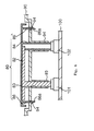
- Figure 6 shows a schematic structure of the operating device.
- the operating device shown in Figure 6 includes an operating button 80, an operating panel 90 that is a holding member for supporting the operating button 80.
- a circuit board 100 is provided on a rear side of the operating panel 90.
- a plurality of switch elements 101, 102 are mounted on the circuit board 100.
- the operating button 80 includes a button body 82 that receives an external pushing action, and a plurality of pushing portions 83, 84 that extend from the button body 82 in the pushing action direction (the downward direction in Figure 6 ). Furthermore, pieces being engaged 86 project from opposite ends of the button body 82 in a direction parallel to the pushing portions 84. Each of the pieces being engaged 86 is provided on a distal end with an engaging pawl 86a.
- the operating panel 90 includes tubular portions 93, 94 that are open in the pushing action direction.
- the pushing portions 83, 84 are inserted into the holding portions 93, 94 from a front side (from an upper side in Figure 6 ). While being inserted, the holding portions 93, 94 hold the pushing portions 83, 84 to guide them in the pushing action direction.
- the operating panel 90 is provided with through-holes 96 that are smaller than the engaging pawls 86a. The engaging pawls 86a are forcedly pushed into the through-holes 96 from a panel front side and reach a rear side of the operating panel 90.
- the respective switch elements 101, 102 are disposed so that the distal ends of the pushing portions 83, 84 can push the elements 101, 102.
- the switch elements 101, 102 apply reaction forces to the pushing portions 83, 84 in a direction opposite to the pushing action direction.
- the reaction forces push the engaging pawls 86a onto the rear side of the operating panel 90 to hold the operating panel 90 at the pushing positions.
- This condition corresponds to a non-operating condition in which no pushing action force is applied to the operating button 80.
- the respective pushing portions 83, 84 further push the switch elements 101, 102, thereby turning the switch elements 101, 102 on.
- the operating device shown in Figure 6 has an object to simplify and downsize a construction and to reduce bounding sounds upon releasing the pushing action.
- the operating device must provide the pieces being engaged 86 that are different from the pushing portions 83, 84 at positions spaced away from the pushing portions 83, 84 on the operating button 80. This will impede simplifying and downsizing of the construction of the operating button 80. If the operating button 80 is released after the operating button 80 is pushed, the engaging pawls 86a strongly strike the rear side of the operating panel 90 by the reaction forces of the switch elements 101, 102 to generate sounds (so-called bounding sounds). These bounding sounds will impede to enhance a quality of the operating device.
- An object of this invention is to provide an operating device that includes an operating member that receives a pushing action, and restricts effectively reduces bounding sounds upon releasing the pushing action from the operating member by a simple and compact structure and further to provide a switch apparatus including the operating apparatus.
- the operating device comprises an operating member for pushing a given switch element in response to an pushing action in a particular pushing action direction, and a holding member for holding said operating member so that the operating member is movable in the pushing action direction.
- the operating member includes a portion being operated that receives the pushing action, a pushing portion that extends from the portion being operated in the pushing action direction and is provided on a distal end with a contact portion that contacts with the switch element, and a portion being engaged that projects from the pushing portion in a direction perpendicular to the pushing action direction.
- the holding member includes a holding portion for holding the operating member so as to guide the operating member in a direction parallel to the pushing action direction, and a deflectable piece that extends from the holding portion toward the switch element and is provided on a distal end with an engaging portion that is deflectable in a direction perpendicular to the pushing action direction.
- the deflectable piece is deflected in a backward direction from the portion being engaged when the pushing portion of the operating member is inserted into the holding portion from a side opposite to the switch element and contacts with the portion being engaged.
- the deflectable piece is disposed at a position where a displacing region of the deflectable piece apart from the switch element is restricted when the engaging portion of the deflectable piece contacts with the portion being engaged from a side opposite to the switch element at a position where the portion being engaged passes over the deflectable piece.
- a combination of the portion being engaged that projects from the pushing portion of the operating member and the deflectable piece provided on the holding member can realize to readily mount the operating member on the holding member. Furthermore, the combination can realize at the same time to restrict the positions of the operating member upon releasing the pushing action and to restrain bounding sounds.
- a switch apparatus includes the above operating device and a switch element to be pushed by the pushing portion of the operating member that receives the pushing action in the operating device.
- the switch element is adapted to apply a reaction force to the pushing portion in a direction opposite to the pushing action direction when the switch element is pushed by the pushing portion and is disposed at a position where the reaction force pushes the portion being engaged of the operating member to the engaging portion.
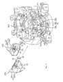
- a switch apparatus of the present invention shown in Figures 1 and 2 is provided in an interior of a motor vehicle.
- the switch apparatus includes an operating panel 10, a plurality of operating buttons 20A, 20B, 20C, 20D, 20E that correspond to operating members, a decoration ring 30, a circuit board 40, an elastic member 50 for a push switch, and a light-guiding member 60.
- the operating panel 10 includes a body panel 10A and a holding panel 10B that corresponds to a holding member.
- the body panel 10A is directed to an interior of a motor vehicle.
- the body panel 10A is provided with an operating section window 12.
- the operating buttons 20A to 20E and decoration ring 30 are disposed inside the operating section window 12.
- the holding panel 10B supports the operating buttons 20A to 20E and decoration ring 30.
- the holding panel 10B is secured at a suitable position on the body panel 10A by a structure (not shown).
- each of the operating buttons 20A to 20E is subject to pushing actions so that a push switch comprising the circuit board 40 and the elastic member 50 for the push switch is turned on.
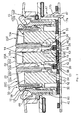
- Each of the operating buttons 20A to 20E includes a button body 22 that is exposed from a front surface of the operating panel 10 and receives the pushing action toward an inner part direction (in a downward direction in Figure 2 ), and a pushing portion 24 that extends from the button body 22 in the pushing action direction.
- each button body 22 is formed into a cap-like configuration.
- each button body 22 includes a top wall 22a that receives the pushing action and a side wall 22b that extends from the top wall 22a in the pushing action direction.
- the holding panel 10B is provided with a holding section for slidably supporting the respective button bodies 22 in the pushing action direction.
- the holding section includes a holding block (only holding blocks 10a, 10c, 10e that correspond to the operating buttons 20A, 20C, 20E are shown in Figure 2 ) that can cover the respective button bodies 22 from the panel front side.
- the holding panel 10B is provided with a guide groove 14 into which each side wall 22b is inserted from the panel front side (downward in Figure 2 ). When each side wall 22b is inserted into each guide groove 14, the respective operating buttons 20A to 20E are held on the holding panel 10B so that the operating buttons 20A to 20E are guided in the pushing action direction.
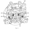
- the operating button 20A out of the operating buttons 20A to 20E is formed into a small circular shape taken from a front side of the operating panel 10 in Figure 1 (taken from an upper side in Figure 2 ) while the other operating buttons 20B to 20E are arranged to surround the operating button 20A.
- Whole peripheral edges of the operating buttons 20B to 20E define a great circular shape.
- the decoration ring 30 is disposed around the outer peripheral edges of the operating buttons 20B to 20E.
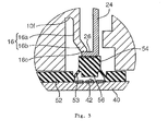
- the decoration ring 30 includes a tubular ring body 32 and a reflection portion 34 that extends outward from a front side end (upper end in Figure 2 ) of the ring body 32.
- the ring body 32 is supported on the holding panel 10B.
- the decoration ring 30 includes a resin matrix and a plating layer (for example, trivalent chrome plating) having a metallic luster and applied on the resin matrix.
- the circuit board 40 is disposed on a rear side of the operating panel 10 substantially in parallel to the body panel 10A.
- the circuit board 40 constitutes a part of each of a plurality of pushing switch elements.
- the circuit board 40 is provided on the surface with a plurality of board side contacts 42 that correspond to a set of contacts out of the switch elements.
- the board side contacts 42 are arranged at positions corresponding to the pushing portions 24 of the operating buttons 20A to 20E.
- a plurality of light sources 44 for illumination are mounted on the circuit board 40, as shown in Figure 1 .
- the light sources 44 are arranged along the decoration ring 30 so as to indirectly illuminate a peripheral area around the decoration ring 30 that constitutes the operating section.
- the lights emitted from the light sources 44 are led to a rear side of the reflection portion 34 of the decoration ring 30 by the light-guiding member 60 ( Figure 2 ) disposed between the reflection portion 34 and the circuit board 40 and are reflected on the rear side of the reflection portion 34 outward from the decoration ring 30 in a radial direction.
- a panel reflection surface 13 formed of the front surface of the body panel 10A is disposed at a position outside the decoration ring 30 in the radial direction. The panel reflection surface 13 reflects the lights to the panel front side to provide illumination lights.
- the circuit board 40 is supported on the side of the body panel 10A by holding pieces 17 ( Figure 2 ) provided on the body panel 10A.
- Each holding piece 17 extends downward from a bottom surface of the body panel 10A and is provided on a distal end with an engaging pawl 17a and on an intermediate part with a branched pushing piece 17b.
- the circuit board 40 is provided with a through-hole 47 that permits the engaging pawl 17a to pass.
- the engaging pawl 17a pushes the bottom surface around the through-hole 47 at a side (bottom side in Figure 2 ) opposite to the body panel 10A, thereby holding the circuit board 40 on the body panel 10A.
- the elastic member 50 for the pushing switch is integrated into a unit and made of an elastic material, such as rubber.
- the elastic member 50 includes a plate-like base 52 and a plurality of elastically displaceable portions 54.
- the base 52 is disposed between the operating panel 10 and the circuit board 40 to be secured between them.
- the base 52 is provided with a plurality of circular through-holes that expose the board side contacts at the front side.
- the elastically displaceable portions 54 are disposed on an area inside the through-holes.
- Each of the elastically displaceable portions 54 is formed into a substantially cylindrical shape and is provided with a bottom surface opposed to each of the board side contacts 42.
- An operating side contact 56 is provided on each of the bottom surfaces of the elastically displaceable portions 54.
- An outer peripheral surface of each elastically displaceable portion 54 is connected through a thin portion 53 to a peripheral edge around each through-hole.
- the thin portion 53 keeps the elastically displaceable portion 54 at a position where the operating side contact 56 and board side contact 42 are spaced apart from each other.
- the thin portion 53 is elastically deformed.
- the elastically displaceable portion 54 is permitted to be elastically displaced in the pushing action direction so as to bring the contacts 56 and 42 into contact with each other.
- the pushing switch including the contacts 56 and 42 are turned on.
- the base 52 of the elastic member 50 for the pushing switch in the present embodiment includes a plate-like base body 52a and a plurality of protrusions 52b and 52c for absorbing a dimension that partially project from a front side of the base body 52a.
- the base 52 and protrusions 52b and 52c are integrated with the base 52.
- the base 52 is clamped between the circuit board 40 and the operating panel 10 with the protrusions 52b and 52c being elastically deformed so as to be compressed in a thickness direction.
- the respective operating buttons 20A to 20E are attached to the common holding panel 10B.
- the holding panel 10B is assembled to the body panel 10A. Accordingly, the holding panel 10B requires a structure for supporting the respecting operating buttons 20A to 20E.
- the respective operating buttons 20A to 20B receives reaction forces (elastic recovery forces of the elastically displaceable portions 54 due to the thin portions 53) from the respective switch elements when the pushing actions are applied to the respective switch elements (that is, when the pushing actions are applied to the elastically displaceable portions 54). Consequently, it is necessary to provide on the holding panel 10B with a structure that holds the respective operating buttons 20A to 20E on given recovery positions upon releasing the pushing actions.
- a portion being engaged 26 projects from a distal end of the pushing portion 24 in a direction perpendicular to the pushing action direction (that is, a direction parallel to the circuit board 40).
- the portion being engaged 26 together with a distal end of the pushing portion 24 contact with a contact portion, that is, an end surface of the panel front side of the elastically displaceable portion 54 to define a pushing portion.
- each of the deflectable pieces 16 includes a base 16a extending from the shoulder portion 10f in the pushing action direction for the operating buttons 20A to 20E, and an inclined portion 16b extending slant toward a side approaching the portion being engaged 26 (right side in Figure 3 ).
- a distal end of the inclined portion 16b defines an engaging portion 16c that can contact with the portion being engaged 26 from a side opposite to the circuit board 40.
- Shapes and positions of the respective deflectable pieces 16 are set to satisfy the following conditions A to C.
- Condition B As shown in Figure 5 , when the engaging portions 16c of the deflectable pieces 16 contact with the portions being engaged 26 from a side opposite to the switch elements at the position where the portions being engaged 26 pass over the deflectable pieces 16, thereby preventing the operating buttons from reversely moving. That is, the operating buttons are restrained from moving to a direction away from the switch elements.
- the engaging portions 16c contact with the portions being engaged 26 at an angle inclined with respect to a direction parallel to the pushing action direction by the slant angle of the inclined portion 16 relative to the base 16a.
- Condition C As shown in Figure 2 , the circuit board 40 is secured to the body panel 10A.
- the holding panel 10B, on which the respective operating buttons 20A to 20E are mounted, is attached to the body panel 10A, as is the case with Condition B. Consequently, as shown in Figure 3 , the contact sections including the distal ends of the pushing portions 24 and the portions being engaged 26 slightly push the elastically displaceable portions 54 of the elastic members 50 for the pushing switch to elastically displace the portions 54 slightly. In other words, relative positions between the elastically displaceable portions 54 and the deflectable pieces 16 are set so that the elastically displaceable portions 54 push slightly the portions being engaged 26 to the engaging portions 16c by a reaction force.
- the combination of the portions being engaged 26 projecting from the pushing portions of the respective operating buttons 20A to 20E and the plural deflectable pieces 16 provided on the holding panel 10B can realize to easily mount the operating buttons 20A to 20B on the holding panel 10B. Furthermore, the combination can realize at the same time to restrict the positions of the operating buttons 20A to 20E upon releasing the pushing actions and to restrain bounding sounds, after the holding panel 10B is attached to the body panel 10A.
- the pushing portion 24 and the portion being engaged 26 are pushed backward by the elastic recovery force of the elastically displaceable portion 54, and the portion being engaged 26 contacts with the engaging portion 16c of the deflectable piece 16 to stop moving. Accordingly, this position restricts a position where the operating button is returned. Furthermore, a slightly deflecting displacement of the engaging portion 16c at the time of contact can effectively restrain any noises caused by the contact (so-called bounding sounds). That is, the deflection of the deflectable piece 16 can contribute to facilitation of attaching the operating panel 10A to the holding panel 10B and restriction of causing the bounding sounds. In particular, since the engaging portion 16c of the deflectable piece 16 in the present embodiment contacts with the portion being engaged 26 in a direction inclined with respect to the inserting direction of the operating buttons 20A to 20E, the deflectable piece 16 is easy to deflect.
- the deflectable piece 16 may extend from the shoulder portion 10f of the holding panel 10B in a slant straight line
- the deflectable piece 16 may include a base 16a that extends in the pushing action direction of the operating button, and a inclined portion 16b that approaches the portion being engaged 26 from a distal end of the base 16a in a slant direction, and a distal end of the inclined portion 16b defines the engaging portion 16c, as shown in Figure 3 .
- This configuration can enlarge an incident angle of the engaging portion 16c relative to the portion being engaged 26 in a limited space, thereby promoting a deflection of the deflectable piece 16 and enhancing an acoustic absorption effect.
- a construction of the operating device can be simplified and downsized in comparison with, for example, the prior art operating device shown in Figure 6 , in which the portions being engaged 86 are disposed on another position spaced away from the pushing portions 83, 84. In other words, it is possible to perform a superior effect by a simple and compact structure.
- the holding panel 10B supports a plurality of operating buttons 20A to 20E and a plurality of deflectable pieces 16 engage the portions being engaged 26 of the operating buttons 20A to 20E. Since the positions of the pushing portions 24 and the portions being engaged 26 are common to the respective operating buttons 20A to 20E, a whole structure of the operating device is significantly simplified and downsized.
- the positions where the portions being engaged 26 project from the pushing portions 24 can be set as required.
- the portions being engaged 26 may project at positions where the portions 26 are spaced away from the switch elements further than the distal ends of the pushing portions 24.
- the portions being engaged 26 project from the distal ends of the pushing portions 24 in a direction perpendicular to the operating action direction to define a part of the contact section together with the distal ends of the pushing portions, it is possible to sufficiently ensure an area for the contact section (an area contacting with the elastically displaceable members 54) while restraining an area in cross section of the pushing portion 24.
- each individual switch element may include a base to be secured to the circuit board or the other member, a portion being operated that is displaceably mounted on the base in an open and closed direction of contacts (an operating action direction), and a spring disposed between the base and the portion being operated to apply a reaction force to the portion being operated at the time of the pushing action.
- the present invention can be applied to the individual switch element.
- the present invention can provide an operating device and a switch apparatus including the operating device that includes an operating member for receiving a pushing action and can effectively reduce bounding sounds upon releasing the pushing action of the operating member by simple and downsized structure.
- the operating device comprises an operating member for pushing a given switch element in response to an pushing action in the pushing action direction, and a holding member for holding said operating member so that the operating member is movable in the pushing action direction.
- the operating member includes a portion being operated that receives the pushing action, a pushing portion that extends from the portion being operated in the pushing action direction and is provided on a distal end with a contact portion that contacts with the switch element, and a portion being engaged that projects from the pushing portion in a direction perpendicular to the pushing action direction.
- the holding member includes a holding portion for holding the operating member so as to guide the operating member in a direction parallel to the pushing action direction, and a deflectable piece that extends from the holding portion toward the switch element and is provided on a distal end with an engaging portion that is deflectable in a direction perpendicular to the pushing action direction.
- the deflectable piece is deflected in a backward direction from the portion being engaged when the pushing portion of the operating member is inserted into the holding portion from a side opposite to the switch element and contacts with the portion being engaged.
- the deflectable piece is disposed at a position where a displacing region of the deflectable piece apart from the switch element is restricted when the engaging portion of the deflectable piece contacts with the portion being engaged from a side opposite to the switch element at a position where the portion being engaged passes over the deflectable piece.
- a combination of the portions being engaged projecting from the pushing portions of the operating member and the deflectable pieces provided on the holding member can realize to readily mount the operating member on the holding member. Furthermore, the combination can realize at the same time to restrict the positions of the operating member upon releasing the pushing action and to restrain bounding sounds.
- the portion being engaged that projects from the pushing portion contacts with the deflectable piece to deflect the piece.
- the portion being engaged passes over the deflectable piece, the deflectable piece returns to the original position due to the elastic recovery force and the engaging portion of the piece contacts with the portion being engaged at the side opposite to the switch element. Consequently, the engaging portion locks the portion being engaged and restricts the operating member from moving away from the switch element.
- the deflection displacement of the deflectable piece can effectively absorb the sounds (that is, the bounding sounds) caused when the portion being engaged strikes the engaging portion of the deflectable piece by the reaction force of the switch element upon releasing the pushing action from the operating member.
- the portion being engaged projects from the pushing portion, a construction of the operating device can be simplified and downsized in comparison with, for example, a prior art operating device in which the portion being engaged is disposed on another position spaced away from the pushing portion.
- the deflectable piece has a shape in which the engaging portion contacts with the portion being engaged from a direction inclined with respect to the pushing action direction of the operating member.
- the engaging portion engages with the portion being engaged in the slant direction, it is possible to promote a deflection of the deflectable piece upon contact and to significantly enhance an acoustic absorption.
- the deflectable piece includes a base that extends from the holding portion in the pushing action direction of the operating member and an inclined portion that extends slant from a distal end of the base in a direction approaching the portion being engaged.
- a distal end of the inclined portion defines the engaging portion. Accordingly, it is possible to increase an incident angle of the engaging portion relative to the portion being engaged and to promote a deflection of the deflectable piece.
- the words "the base extends in the pushing action direction of the operating member” do not mean that the base is completely parallel to the pushing action direction of the operating member.
- a detailed shape of the base is not limited.
- a position where the portion being engaged projects from the pushing portion can be set, as required.
- the portion being engaged projects from the distal end of the pushing portion in a direction perpendicular to the pushing action direction to define a part of the contact portion.
- the portion being engaged defines a part of the contact portion together with the distal end of the pushing portion, it is possible to sufficiently ensure an area of the contact portion (that is, a contact area between the operating member and the switch element) without increasing an area in cross section of the pushing portion.
- An operating device may include a plurality of operating members.
- holding portions of the holding member hold the operating members, respectively and the holding members include a plurality of deflectable pieces that engage the portion being engaged of the operating members, respectively.
- the positions of the pushing portion and the portion being engaged in the operating member are shared with each other, a whole construction of the device can be significantly simplified and downsized.
- the present invention provides the above operating device and a switch apparatus including a switch element to be pushed by the pushing portion of the operating member that receives the pushing action in the operating device.
- the switch element in the switch apparatus is adapted to apply a reaction force to the pushing portion in a direction opposite to the pushing action direction when the switch element is pushed by the pushing portion and is disposed at a position where the reaction force pushes the portion being engaged of the operating member to the engaging portion.
Landscapes
- Push-Button Switches (AREA)
- Mechanisms For Operating Contacts (AREA)
- Electrophonic Musical Instruments (AREA)
- Switch Cases, Indication, And Locking (AREA)
Applications Claiming Priority (2)
| Application Number | Priority Date | Filing Date | Title |
|---|---|---|---|
| JP2008031185A JP5056451B2 (ja) | 2008-02-13 | 2008-02-13 | 操作装置及びこれを備えたスイッチ装置 |
| PCT/JP2008/064627 WO2009101720A1 (ja) | 2008-02-13 | 2008-08-15 | 押圧操作を受ける操作装置及びこれを備えたスイッチ装置 |
Publications (3)
| Publication Number | Publication Date |
|---|---|
| EP2242072A1 true EP2242072A1 (de) | 2010-10-20 |
| EP2242072A4 EP2242072A4 (de) | 2011-01-26 |
| EP2242072B1 EP2242072B1 (de) | 2012-01-04 |
Family
ID=40956764
Family Applications (1)
| Application Number | Title | Priority Date | Filing Date |
|---|---|---|---|
| EP08872421A Not-in-force EP2242072B1 (de) | 2008-02-13 | 2008-08-15 | Betriebsmechanismus mit drückbedienung und schaltervorrichtung damit |
Country Status (5)
| Country | Link |
|---|---|
| EP (1) | EP2242072B1 (de) |
| JP (1) | JP5056451B2 (de) |
| CN (1) | CN101627451B (de) |
| AT (1) | ATE540417T1 (de) |
| WO (1) | WO2009101720A1 (de) |
Families Citing this family (1)
| Publication number | Priority date | Publication date | Assignee | Title |
|---|---|---|---|---|
| WO2017041229A1 (zh) * | 2015-09-08 | 2017-03-16 | 王为明 | 键盘装置 |
Family Cites Families (7)
| Publication number | Priority date | Publication date | Assignee | Title |
|---|---|---|---|---|
| JPH03130126U (de) * | 1990-04-11 | 1991-12-26 | ||
| JP3296610B2 (ja) * | 1993-01-29 | 2002-07-02 | 三洋電機株式会社 | 電子装置の押しボタン操作部 |
| US5670759A (en) * | 1995-07-14 | 1997-09-23 | Acer Peripherals, Inc. | Push button switch including complementary housing and actuator polygonal shapes |
| JP3794068B2 (ja) * | 1996-09-17 | 2006-07-05 | 松下電器産業株式会社 | プッシュオンスイッチ |
| JPH1139989A (ja) * | 1997-07-16 | 1999-02-12 | Denso Corp | プッシュ式スイッチ装置 |
| JP4535626B2 (ja) * | 2001-01-31 | 2010-09-01 | 富士通コンポーネント株式会社 | キースイッチ装置及びキーボード |
| JP2006059562A (ja) * | 2004-08-17 | 2006-03-02 | Tokai Rika Co Ltd | スイッチ装置 |
-
2008
- 2008-02-13 JP JP2008031185A patent/JP5056451B2/ja not_active Expired - Fee Related
- 2008-08-15 WO PCT/JP2008/064627 patent/WO2009101720A1/ja not_active Ceased
- 2008-08-15 CN CN2008800066815A patent/CN101627451B/zh not_active Expired - Fee Related
- 2008-08-15 EP EP08872421A patent/EP2242072B1/de not_active Not-in-force
- 2008-08-15 AT AT08872421T patent/ATE540417T1/de active
Also Published As
| Publication number | Publication date |
|---|---|
| CN101627451B (zh) | 2012-10-10 |
| WO2009101720A1 (ja) | 2009-08-20 |
| JP5056451B2 (ja) | 2012-10-24 |
| JP2009193735A (ja) | 2009-08-27 |
| EP2242072A4 (de) | 2011-01-26 |
| EP2242072B1 (de) | 2012-01-04 |
| CN101627451A (zh) | 2010-01-13 |
| ATE540417T1 (de) | 2012-01-15 |
Similar Documents
| Publication | Publication Date | Title |
|---|---|---|
| US10794564B2 (en) | Back door handle device | |
| JP7052619B2 (ja) | バックドアハンドル装置及びその製造方法 | |
| KR100883945B1 (ko) | 회전 조작형 전기 부품 | |
| JP4985444B2 (ja) | 照明機能を有する操作装置 | |
| WO2019189663A1 (ja) | サウンド機能付押ボタンスイッチ | |
| JP6010754B2 (ja) | プッシュロック体及びこれを用いた入力装置 | |
| EP2242072B1 (de) | Betriebsmechanismus mit drückbedienung und schaltervorrichtung damit | |
| US6888079B2 (en) | Multifunctional pushbutton switch | |
| CN101226838A (zh) | 开关 | |
| CN104658793B (zh) | 输入设备,按键钮、开关和框,电路板和减少行程的方法 | |
| US6987231B2 (en) | Multifunctional pushbutton switch | |
| KR20170070578A (ko) | 차량의 푸쉬 락 스위치 장치 | |
| JP3201700B2 (ja) | スイッチ | |
| US6149189A (en) | Cover cap for an airbag unit | |
| JP4063753B2 (ja) | ジョイスティック型入力装置 | |
| KR100778053B1 (ko) | 차량 탑재용 노브 스위치장치 | |
| JP2008234934A (ja) | スイッチ装置 | |
| JP2007005103A (ja) | キートップの押圧スイッチ部への取付方法、及び押圧スイッチ部 | |
| US5777282A (en) | Push-button switch | |
| KR102068573B1 (ko) | 자동차의 시동용 스위치 장치 | |
| JP2001273833A (ja) | スイッチ構造 | |
| JP2007123193A (ja) | キースイッチ | |
| JP2012099241A (ja) | 押釦スイッチ | |
| JP2009009776A (ja) | スイッチ構造 | |
| EP4538092A1 (de) | Druckknopfschalter für fahrzeuge, insbesondere für fahrzeugtürverkleidungen |
Legal Events
| Date | Code | Title | Description |
|---|---|---|---|
| PUAI | Public reference made under article 153(3) epc to a published international application that has entered the european phase |
Free format text: ORIGINAL CODE: 0009012 |
|
| 17P | Request for examination filed |
Effective date: 20090914 |
|
| AK | Designated contracting states |
Kind code of ref document: A1 Designated state(s): AT BE BG CH CY CZ DE DK EE ES FI FR GB GR HR HU IE IS IT LI LT LU LV MC MT NL NO PL PT RO SE SI SK TR |
|
| AX | Request for extension of the european patent |
Extension state: AL BA MK RS |
|
| A4 | Supplementary search report drawn up and despatched |
Effective date: 20101229 |
|
| DAX | Request for extension of the european patent (deleted) | ||
| GRAP | Despatch of communication of intention to grant a patent |
Free format text: ORIGINAL CODE: EPIDOSNIGR1 |
|
| RTI1 | Title (correction) |
Free format text: OPERATING DEVICE FOR RECEIVING A PUSHING ACTION AND SWITCH DEVICE INCLUDING THE SAME |
|
| GRAS | Grant fee paid |
Free format text: ORIGINAL CODE: EPIDOSNIGR3 |
|
| GRAA | (expected) grant |
Free format text: ORIGINAL CODE: 0009210 |
|
| AK | Designated contracting states |
Kind code of ref document: B1 Designated state(s): AT BE BG CH CY CZ DE DK EE ES FI FR GB GR HR HU IE IS IT LI LT LU LV MC MT NL NO PL PT RO SE SI SK TR |
|
| REG | Reference to a national code |
Ref country code: GB Ref legal event code: FG4D |
|
| REG | Reference to a national code |
Ref country code: CH Ref legal event code: EP |
|
| REG | Reference to a national code |
Ref country code: AT Ref legal event code: REF Ref document number: 540417 Country of ref document: AT Kind code of ref document: T Effective date: 20120115 |
|
| REG | Reference to a national code |
Ref country code: IE Ref legal event code: FG4D |
|
| REG | Reference to a national code |
Ref country code: DE Ref legal event code: R096 Ref document number: 602008012548 Country of ref document: DE Effective date: 20120308 |
|
| REG | Reference to a national code |
Ref country code: NL Ref legal event code: VDEP Effective date: 20120104 |
|
| PG25 | Lapsed in a contracting state [announced via postgrant information from national office to epo] |
Ref country code: SI Free format text: LAPSE BECAUSE OF FAILURE TO SUBMIT A TRANSLATION OF THE DESCRIPTION OR TO PAY THE FEE WITHIN THE PRESCRIBED TIME-LIMIT Effective date: 20120104 |
|
| LTIE | Lt: invalidation of european patent or patent extension |
Effective date: 20120104 |
|
| PG25 | Lapsed in a contracting state [announced via postgrant information from national office to epo] |
Ref country code: BE Free format text: LAPSE BECAUSE OF FAILURE TO SUBMIT A TRANSLATION OF THE DESCRIPTION OR TO PAY THE FEE WITHIN THE PRESCRIBED TIME-LIMIT Effective date: 20120104 Ref country code: NL Free format text: LAPSE BECAUSE OF FAILURE TO SUBMIT A TRANSLATION OF THE DESCRIPTION OR TO PAY THE FEE WITHIN THE PRESCRIBED TIME-LIMIT Effective date: 20120104 Ref country code: BG Free format text: LAPSE BECAUSE OF FAILURE TO SUBMIT A TRANSLATION OF THE DESCRIPTION OR TO PAY THE FEE WITHIN THE PRESCRIBED TIME-LIMIT Effective date: 20120404 Ref country code: IS Free format text: LAPSE BECAUSE OF FAILURE TO SUBMIT A TRANSLATION OF THE DESCRIPTION OR TO PAY THE FEE WITHIN THE PRESCRIBED TIME-LIMIT Effective date: 20120504 Ref country code: LT Free format text: LAPSE BECAUSE OF FAILURE TO SUBMIT A TRANSLATION OF THE DESCRIPTION OR TO PAY THE FEE WITHIN THE PRESCRIBED TIME-LIMIT Effective date: 20120104 Ref country code: NO Free format text: LAPSE BECAUSE OF FAILURE TO SUBMIT A TRANSLATION OF THE DESCRIPTION OR TO PAY THE FEE WITHIN THE PRESCRIBED TIME-LIMIT Effective date: 20120404 Ref country code: HR Free format text: LAPSE BECAUSE OF FAILURE TO SUBMIT A TRANSLATION OF THE DESCRIPTION OR TO PAY THE FEE WITHIN THE PRESCRIBED TIME-LIMIT Effective date: 20120104 |
|
| PG25 | Lapsed in a contracting state [announced via postgrant information from national office to epo] |
Ref country code: GR Free format text: LAPSE BECAUSE OF FAILURE TO SUBMIT A TRANSLATION OF THE DESCRIPTION OR TO PAY THE FEE WITHIN THE PRESCRIBED TIME-LIMIT Effective date: 20120405 Ref country code: LV Free format text: LAPSE BECAUSE OF FAILURE TO SUBMIT A TRANSLATION OF THE DESCRIPTION OR TO PAY THE FEE WITHIN THE PRESCRIBED TIME-LIMIT Effective date: 20120104 Ref country code: PL Free format text: LAPSE BECAUSE OF FAILURE TO SUBMIT A TRANSLATION OF THE DESCRIPTION OR TO PAY THE FEE WITHIN THE PRESCRIBED TIME-LIMIT Effective date: 20120104 Ref country code: PT Free format text: LAPSE BECAUSE OF FAILURE TO SUBMIT A TRANSLATION OF THE DESCRIPTION OR TO PAY THE FEE WITHIN THE PRESCRIBED TIME-LIMIT Effective date: 20120504 Ref country code: FI Free format text: LAPSE BECAUSE OF FAILURE TO SUBMIT A TRANSLATION OF THE DESCRIPTION OR TO PAY THE FEE WITHIN THE PRESCRIBED TIME-LIMIT Effective date: 20120104 |
|
| REG | Reference to a national code |
Ref country code: AT Ref legal event code: MK05 Ref document number: 540417 Country of ref document: AT Kind code of ref document: T Effective date: 20120104 |
|
| PG25 | Lapsed in a contracting state [announced via postgrant information from national office to epo] |
Ref country code: CY Free format text: LAPSE BECAUSE OF FAILURE TO SUBMIT A TRANSLATION OF THE DESCRIPTION OR TO PAY THE FEE WITHIN THE PRESCRIBED TIME-LIMIT Effective date: 20120104 |
|
| PG25 | Lapsed in a contracting state [announced via postgrant information from national office to epo] |
Ref country code: RO Free format text: LAPSE BECAUSE OF FAILURE TO SUBMIT A TRANSLATION OF THE DESCRIPTION OR TO PAY THE FEE WITHIN THE PRESCRIBED TIME-LIMIT Effective date: 20120104 Ref country code: EE Free format text: LAPSE BECAUSE OF FAILURE TO SUBMIT A TRANSLATION OF THE DESCRIPTION OR TO PAY THE FEE WITHIN THE PRESCRIBED TIME-LIMIT Effective date: 20120104 Ref country code: DK Free format text: LAPSE BECAUSE OF FAILURE TO SUBMIT A TRANSLATION OF THE DESCRIPTION OR TO PAY THE FEE WITHIN THE PRESCRIBED TIME-LIMIT Effective date: 20120104 Ref country code: CZ Free format text: LAPSE BECAUSE OF FAILURE TO SUBMIT A TRANSLATION OF THE DESCRIPTION OR TO PAY THE FEE WITHIN THE PRESCRIBED TIME-LIMIT Effective date: 20120104 Ref country code: SE Free format text: LAPSE BECAUSE OF FAILURE TO SUBMIT A TRANSLATION OF THE DESCRIPTION OR TO PAY THE FEE WITHIN THE PRESCRIBED TIME-LIMIT Effective date: 20120104 |
|
| PLBE | No opposition filed within time limit |
Free format text: ORIGINAL CODE: 0009261 |
|
| STAA | Information on the status of an ep patent application or granted ep patent |
Free format text: STATUS: NO OPPOSITION FILED WITHIN TIME LIMIT |
|
| PG25 | Lapsed in a contracting state [announced via postgrant information from national office to epo] |
Ref country code: IT Free format text: LAPSE BECAUSE OF FAILURE TO SUBMIT A TRANSLATION OF THE DESCRIPTION OR TO PAY THE FEE WITHIN THE PRESCRIBED TIME-LIMIT Effective date: 20120104 Ref country code: SK Free format text: LAPSE BECAUSE OF FAILURE TO SUBMIT A TRANSLATION OF THE DESCRIPTION OR TO PAY THE FEE WITHIN THE PRESCRIBED TIME-LIMIT Effective date: 20120104 |
|
| 26N | No opposition filed |
Effective date: 20121005 |
|
| PG25 | Lapsed in a contracting state [announced via postgrant information from national office to epo] |
Ref country code: AT Free format text: LAPSE BECAUSE OF FAILURE TO SUBMIT A TRANSLATION OF THE DESCRIPTION OR TO PAY THE FEE WITHIN THE PRESCRIBED TIME-LIMIT Effective date: 20120104 |
|
| REG | Reference to a national code |
Ref country code: DE Ref legal event code: R097 Ref document number: 602008012548 Country of ref document: DE Effective date: 20121005 |
|
| REG | Reference to a national code |
Ref country code: CH Ref legal event code: PL |
|
| PG25 | Lapsed in a contracting state [announced via postgrant information from national office to epo] |
Ref country code: MC Free format text: LAPSE BECAUSE OF NON-PAYMENT OF DUE FEES Effective date: 20120831 |
|
| GBPC | Gb: european patent ceased through non-payment of renewal fee |
Effective date: 20120815 |
|
| PG25 | Lapsed in a contracting state [announced via postgrant information from national office to epo] |
Ref country code: CH Free format text: LAPSE BECAUSE OF NON-PAYMENT OF DUE FEES Effective date: 20120831 Ref country code: ES Free format text: LAPSE BECAUSE OF FAILURE TO SUBMIT A TRANSLATION OF THE DESCRIPTION OR TO PAY THE FEE WITHIN THE PRESCRIBED TIME-LIMIT Effective date: 20120415 Ref country code: LI Free format text: LAPSE BECAUSE OF NON-PAYMENT OF DUE FEES Effective date: 20120831 |
|
| REG | Reference to a national code |
Ref country code: IE Ref legal event code: MM4A |
|
| PG25 | Lapsed in a contracting state [announced via postgrant information from national office to epo] |
Ref country code: GB Free format text: LAPSE BECAUSE OF NON-PAYMENT OF DUE FEES Effective date: 20120815 Ref country code: IE Free format text: LAPSE BECAUSE OF NON-PAYMENT OF DUE FEES Effective date: 20120815 |
|
| PG25 | Lapsed in a contracting state [announced via postgrant information from national office to epo] |
Ref country code: MT Free format text: LAPSE BECAUSE OF FAILURE TO SUBMIT A TRANSLATION OF THE DESCRIPTION OR TO PAY THE FEE WITHIN THE PRESCRIBED TIME-LIMIT Effective date: 20120104 |
|
| PG25 | Lapsed in a contracting state [announced via postgrant information from national office to epo] |
Ref country code: TR Free format text: LAPSE BECAUSE OF FAILURE TO SUBMIT A TRANSLATION OF THE DESCRIPTION OR TO PAY THE FEE WITHIN THE PRESCRIBED TIME-LIMIT Effective date: 20120104 |
|
| PG25 | Lapsed in a contracting state [announced via postgrant information from national office to epo] |
Ref country code: LU Free format text: LAPSE BECAUSE OF NON-PAYMENT OF DUE FEES Effective date: 20120815 |
|
| PG25 | Lapsed in a contracting state [announced via postgrant information from national office to epo] |
Ref country code: HU Free format text: LAPSE BECAUSE OF FAILURE TO SUBMIT A TRANSLATION OF THE DESCRIPTION OR TO PAY THE FEE WITHIN THE PRESCRIBED TIME-LIMIT Effective date: 20080815 |
|
| REG | Reference to a national code |
Ref country code: FR Ref legal event code: PLFP Year of fee payment: 9 |
|
| REG | Reference to a national code |
Ref country code: DE Ref legal event code: R084 Ref document number: 602008012548 Country of ref document: DE |
|
| REG | Reference to a national code |
Ref country code: FR Ref legal event code: PLFP Year of fee payment: 10 |
|
| PGFP | Annual fee paid to national office [announced via postgrant information from national office to epo] |
Ref country code: FR Payment date: 20170714 Year of fee payment: 10 Ref country code: DE Payment date: 20170808 Year of fee payment: 10 |
|
| REG | Reference to a national code |
Ref country code: DE Ref legal event code: R119 Ref document number: 602008012548 Country of ref document: DE |
|
| PG25 | Lapsed in a contracting state [announced via postgrant information from national office to epo] |
Ref country code: DE Free format text: LAPSE BECAUSE OF NON-PAYMENT OF DUE FEES Effective date: 20190301 |
|
| PG25 | Lapsed in a contracting state [announced via postgrant information from national office to epo] |
Ref country code: FR Free format text: LAPSE BECAUSE OF NON-PAYMENT OF DUE FEES Effective date: 20180831 |