EP2243637B1 - Appareil d'insertion d'enveloppes - Google Patents
Appareil d'insertion d'enveloppes Download PDFInfo
- Publication number
- EP2243637B1 EP2243637B1 EP09158754.3A EP09158754A EP2243637B1 EP 2243637 B1 EP2243637 B1 EP 2243637B1 EP 09158754 A EP09158754 A EP 09158754A EP 2243637 B1 EP2243637 B1 EP 2243637B1
- Authority
- EP
- European Patent Office
- Prior art keywords
- document
- envelope
- steering
- arrangement
- inserting apparatus
- Prior art date
- Legal status (The legal status is an assumption and is not a legal conclusion. Google has not performed a legal analysis and makes no representation as to the accuracy of the status listed.)
- Not-in-force
Links
Images
Classifications
-
- B—PERFORMING OPERATIONS; TRANSPORTING
- B43—WRITING OR DRAWING IMPLEMENTS; BUREAU ACCESSORIES
- B43M—BUREAU ACCESSORIES NOT OTHERWISE PROVIDED FOR
- B43M3/00—Devices for inserting documents into envelopes
- B43M3/04—Devices for inserting documents into envelopes automatic
- B43M3/045—Devices for inserting documents into envelopes automatic for envelopes with only one flap
Definitions
- the invention relates to an inserting apparatus for inserting documents into envelopes.
- Such an inserting apparatus may comprise an envelope holder for holding an envelope in a document inserting position and a document inserting path arranged upstream of the envelope holder for feeding at least one document to the envelope, which envelope at the moment of insertion is opened at a first upstream end thereof for receiving said document.
- the inserting apparatus may further comprise a document displacement arrangement for displacement of the document at least along the document inserting path into the envelope.
- Such a displacement arrangement comprises at least one displacement element that is adapted to push the document into the envelope.
- the inserting apparatus may comprise guiding elements arranged on both sides along the document inserting path to align the at least one document with the envelope in the inserting position.
- the document may collide with an inner side of the envelope.
- a collision may be the result of a displacement of the document with respect to the envelope before insertion, for instance due to friction of the document at one of the lateral sides of the document and for instance the guiding elements.
- such a collision may actually result in a displacement of the document with respect to the envelope before complete insertion of the document into the envelope. Due to the skew of the document relative to the envelope, the document may get stuck or get damaged resulting in obstruction of the envelope inserting process. For instance, a jam of documents may occur in the inserting apparatus. In that case time consuming operations may be necessary because the apparatus has to be stopped and the jam of documents has to be removed. This may result in a negative effect on overall productivity of such inserting apparatuses.
- an inserting apparatus for inserting documents into envelopes according to claim 1 is provided.
- Providing a document steering arrangement upstream of the envelope holder prevents rotation of the document with respect to the envelope due to collision of said document with the envelope.
- the arrangement further allows aligning of the document relative to the envelope at the latest possible moment before insertion of the document into the envelope.
- the document steering arrangement is positioned opposite of an envelope crease line provided between an envelope flap and an envelope body when the envelope is in the document inserting position.
- the envelope flap extends in an upstream direction from the envelope part of the envelope body facing away from the document steering arrangement.
- the document Upon displacement of the document by means of the document displacement arrangement, the document is displaced along the document inserting path towards the envelope.
- the document Before entering the envelope inner space, the document abuts with the steering elements of the document steering arrangement that are spaced apart along a steering arrangement central axis that in use is substantially aligned with the envelope crease line.
- the side of the document facing the envelope will abut with both steering elements approximately at the same moment in time. Due to the fact that the steering elements are interconnected, the steering elements start rotating about the central axis in a similar direction with a similar speed during a similar time interval resulting in a displacement of the document in the inserting direction.
- the document Due to the force that is applied by the steering elements to the document, the document is prevented from rotation and displacement upon contacting the envelope. In case the document is skewed with respect to the envelope before reaching the envelope, the document will abut with one of the steering elements first. Due to the friction applied to the document by the steering element as result of the initial rotation force of that steering element, the displacement in the inserting direction of part of the document facing said steering element is slowed down. Consequently, the document at least at the position of the second steering element is displaced such that it also abuts the second steering element. At that moment, the document is aligned and can be displaced by the steering elements as described above.
- both steering elements start rotating when at least one of the steering elements is rotated by the document that is contacting said steering element.
- the steering elements apply a force to the document that prevents the document from rotating just before inserting it into the envelope.
- the document steering arrangement may correct the position of the document with respect to the envelope and may keep the document in the aligned position. Consequently, inserting efficiency of the inserting apparatus is improved with a relatively simple arrangement that is provided upstream of the envelope holder.
- document refers to at least one or more documents, magazines, books and other suitable inserts such as a CD, DVD or the like and any combination thereof.
- EP 1,304,305 discloses a system for aligning a moving stack of sheets.
- the system comprises a gathering section and an envelope feeder/inserter station.
- the gathering section includes a plurality of enclosure feeders for separately releasing documents.
- the documents are pushed toward the envelope feeder/inserter station by pushing fingers, which are attached to an endless chain for movement.
- the documents reach the envelope feeder/ inserter station they are collated into a stack comprising of a plurality of sheets.
- the documents if skewed to one side or another, are aligned with the trailing edge of the other documents in the stack by means of the pushing fingers.
- the system comprises an alignment system comprising a pair of cams separately mounted on shafts for rotation.
- the cams are positioned at opposite sides of a center line which is parallel to the moving direction of the documents.
- the cams are driven to rotate synchronously with each other in opposite directions.
- the outer surfaces of the cam face each other to define a gate with a gate width that is reduced during rotation of the cams to align the documents in the stack.
- US 2003/0020231 discloses a sheet registration system for printers for controlling correcting or changing the orientation and/or position of sheets traveling in a sheet transport path.
- the system comprises two laterally spaced sheet drive rollers that are both driven by a servo motor. Mating idler rollers are provided for forming the first and second drive nips. During feeding of the sheets to the printer, the nips are driven at the same rotational speed. Upon detection of a sheet in a skewed condition by a sensor, the two driven rollers that are mounted on different shafts are driven with a different speed to deskew the sheet.
- EP 0,473,884 discloses a system for aligning sheets in printers.
- the system includes two drive rollers for driving individual sheets back and forth on the planar surface towards a printing station.
- the system further comprises a wobble roller mounted in opposition to a first drive roller for pivoting in the direction of sheet travel.
- a pinch roller is provided.
- the wobble roller is arranged for pulling the lateral edges of the sheets into parallel, abutting contact with a guide rail that extends parallel to the sheet travel direction.
- the drive rollers are mounted on a common driving shaft to be driven by a drive motor.
- To align the sheet the pinch roller is disengaged and the wobble roller is moved into engagement with a sheet.
- the axel of the roller begins to pivot in the forward direction such that the wobble roller applies force by frictional engagement with the sheet such that the sheet is moved toward the guide rail.
- the document displacement arrangement may comprise at least two pushing fingers that form the displacement elements, which pushing fingers are spaced apart and arranged transversely with respect to the document inserting path.
- the steering arrangement may align the document such that the side of the document facing the pushing fingers is pushed against both fingers resulting in an effective displacement of the document along the inserting path.
- a distance between the respective steering elements may be smaller than a distance between the respective pushing fingers such that the steering elements are positioned between the inserting fingers in a direction substantially perpendicular to the document inserting path. It may be advantageous, according to a further aspect of the invention, if the distance between the respective steering elements is as large as possible. Thus, preferably the respective steering elements are positioned adjacent the respective pushing fingers.
- a support surface may be provided in the inserting apparatus between the respective steering elements to support a middle part of the document and thus prevent buckling of the document between the steering elements. This may increase the proper functioning of the document steering arrangement, for instance in case the document has a minimal thickness.
- the inserting apparatus comprises lifting means arranged such that the document steering arrangement is liftable with respect to the document inserting path.
- the document steering arrangement By lifting the document steering arrangement, documents with a relatively large length in a direction substantially parallel to the inserting direction or documents that are sensitive to bending in said direction and that pass the document steering arrangement may be lifted such that buckling of the document between the document inserting arrangement and the document displacement arrangement is prevented.
- the document is lifted at the moment the document starts running along the steering elements. This provides an inserting apparatus with increased operating efficiency for large documents as well.
- the document steering elements may be drivable, for instance in reaction to a signal from a sensor, such as a position sensor, arranged in the apparatus for detecting of a document position, in order to actively rotate the respective steering elements.
- a sensor such as a position sensor
- Such drivable steering elements may be arranged additionally to or instead of the lifting means.
- the steering elements may be driven at the moment the document has passed the steering elements and starts to enter the inner space of the envelope.
- the inserting apparatus may comprise a detection unit to detect the position of the document with respect to the envelope.
- the detection unit may comprise an indicator rotatably arranged to the document steering arrangement and adapted to rotate during passing of a document and a sensor adapted to determine a displacement of the indicator.
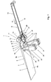
- the inserting apparatus 1 for inserting documents 2 into envelopes 4 according to the example as shown in Figures 1-5 is first described with reference to Figure 1 .
- the inserting apparatus 1 that is shown in Figure 1 can be mounted on or be part of a system for processing documents, for instance downstream of a copying system or a printing system.
- the inserting apparatus 1 comprises an envelope holder 3 that holds the envelope 4 in the document inserting position as shown in Figure 1 .
- the envelope 4 can be fed to the envelope holder from an envelope storage along an envelope feeding path (not shown).
- a document inserting path 8 is arranged that in use feeds documents 2 to the envelope 4 that, at least the end of the envelope 4 facing the document inserting path 8, is in an open position,.
- the inserting apparatus 1 further comprises a document displacement arrangement 10.
- the displacement arrangement 10 is arranged for displacing the document 2 along the inserting path 8 in the inserting direction Ri into the envelope 4.
- the arrangement 10 comprises two displacement elements 11, in this example two pushing fingers 11 that are provided transversally relative to the document inserting path 8 and which are mutually spaced apart.
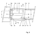
- a distance D (see Fig. 3 ) between said pushing fingers 11 does not exceed approximately 120mm such that the inserting apparatus 1 can be used for relatively small documents 2 for inserting into small envelopes 3 with an envelope width that does not exceed approximately 130mm.
- the pushing fingers 11 are arranged on an endless belt 12 that is displaceable in the document inserting direction Ri. Adjacent the end of the document inserting path 8 facing the envelope holder 3; supplementary transporting rollers 13 are provided arranged such that in use a document 2 to be inserted passes between said transporting rollers 13.
- the inserting apparatus 1 further comprises a document steering arrangement 14.
- the document steering arrangement 14 is arranged upstream of the envelope holder 3. In use, the document steering arrangement 14 is located opposite to the envelope crease line 7, which is provided between the envelope flap 5 and the envelope body 6 of the envelope 4. When the envelope 4 is received in the envelope holder 3, the envelope flap 5 extends from an upper part 4a of the envelope 4 in a direction opposite to the inserting direction Ri.
- the document steering arrangement 14 comprises two steering elements 15, in this example two rollers 15 that are spaced apart along a central axis A (see also Fig. 3 ) of the steering arrangement 14.
- the crease line 7 of the envelope 4 is substantially aligned with the central axis A.
- the steering elements 15 are interconnected such that said steering elements 15 are rotatable about the central axis A in a similar rotational direction during a similar time interval. In different words, if one of the steering elements 15 starts rotating, the other one of the steering elements 15 starts rotating as well in the same direction with the same speed.
- the steering elements 15 are connected to an axle 16 that extends along the central axis A.
- the steering rollers 15 preferably have a diameter of approximately between 20-30 mm and are connected at mutual distance to the axle 16, wherein the distance d (see Fig. 3 ) between the respective rollers 15 preferably is as large as possible.
- the distance between the rollers 15, however, is smaller than the distance D between the respective pushing fingers 11, such that the rollers 15 are positioned between the inserting fingers 11 seen in a direction substantially perpendicular to the document inserting path 8.
- the inserting apparatus 1 can be used for envelopes 4 having a relatively small width as explained before.
- the inserting apparatus 1 is also provided with an envelope opening device 20, that is adapted to open a throat of the envelope 4 before the document 2 to be inserted, reaches the envelope 4.
- the inserting apparatus 1 may be arranged downstream of a document collator (not shown) that collates an amount of documents 2 that are subsequently transported along the document inserting path 8 towards the inserting apparatus 1.
- the amount of documents 2 (for the sake of clarity further indicated as document 2) is pushed by means of the pushing fingers 11 in the inserting direction Ri.
- an envelope 4 is fed to the envelope holder 3 and the flap 5 is opened such that the flap 5 extends from the upper part 4a of the envelope body 6.
- the envelope 4 is held at the flap 5 in the envelope holder 3.
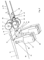
- the envelope opening device 20 comprises two suction cylinders 21 and two hook elements 22 that are mechanically coupled to the respective suction cylinders 21.
- the distance between the respective suction cylinders 21 can be adjusted to a width of the envelope 4.
- the suction cylinder 21 is pushed against an outer surface of the lower part 4b of the envelope body 6, which is clearly shown in Fig. 2 .
- the piston 23 is pushed into the cylinder 21 such that air from within the cylinder 21 leaves said cylinder 21 via a small non-return valve (not shown).
- the hook element 22 is retracted.
- the cylinder 21 is moved in a direction away from the envelope 4, at the same time pushing the piston 23 out of the cylinder 21.
- the suction cup 24, that is located at the end of the piston 23 facing the envelope 4 is pushed against the envelope 4.
- a vacuum that is created in the suction cup 24 pulls the lower part 4b of the envelope body 6 from the upper part 4a of the envelope body 6 thereby opening the throat of the envelope 4.
- the hook element 22 is able to enter the throat of the envelope 4 to keep the throat in an open position after removal of the vacuum.
- the pushing fingers 11 continue to push the document 2 towards the envelope 4 such that the document 2 passes the additional roller pairs 13 and subsequently reaches the document steering arrangement 14.
- the document 2 Upon contacting the steering rollers 15 of the steering arrangement 14, the document 2 is subjected to a certain resistance provided by the steering rollers 15.
- the interaction of the document 2 with at least one of the steering rollers 15 results in rotation of the steering rollers 15.
- the steering arrangement 14 is arranged such that the steering elements 15 apply a press-on force of approximately 0.25-1 Newton to the envelope 4, at least to the envelope crease line 7. Due to this force, the document 2 is prevented from rotating just before and during insertion of the document 2 into the envelope 4.
- the document steering arrangement 14 may correct the document alignment with respect to the alignment of the envelope. This will be explained now referring to Fig. 3 .
- a first part of the document 2 for instance in this example a first document corner 2a reaches the first steering roller 15a before the second steering roller 15b is reached by the document 2.
- the first steering roller 15a offers resistance to the first document corner 2a such that the displacement speed of the document locally decreases. Then the document 2 rotates in direction Ra resulting in displacement of the corner 2c of the document 2, that faces the first pushing finger 11a, towards said pushing finger 11a.
- the document 2 is aligned with respect to the envelope 4 and stays aligned due to the press-on force of the document steering arrangement 14 as explained before.
- the press-on force may be applied to the envelope 4 by means of a leaf spring 18 that is provided between the document steering arrangement 14 and the inserting apparatus 1, as shown in Figs 1 and 2 .
- guiding elements may be provided at opposing outer sides of the document steering arrangement 14 at least partly along the document inserting path 8. The guiding elements may align the document 2 just before reaching the document steering arrangement 14, for instance by displacing the document in transversal direction with respect to the document inserting path 8.
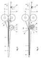
- the inserting apparatus 1 may be provided with lifting means 25 that are arranged to lift the document steering arrangement 14 with respect to the document inserting path 8 (see Figs. 2 and 4 ).
- the lifting means 25 may comprise a lifting element 26, in this example the leaf spring 18, and an actuator 27 provided at the end of the leaf spring 18 facing away from the document steering arrangement 14.
- the actuator 27 comprises an operating lever 28 that is operated by the pushing finger 11 upon passing said lever 28. Lifting of the document 2 may be advantageous in case there is a risk that the document 2 may buckle down between the pushing fingers 11 and the document steering arrangement 14, for instance in case the document has a relatively large length.
- the actuator 27 comprises a second operating lever 29 arranged such with respect to the first operating lever 28 that upon displacement of the first operating lever 28 by the pushing finger 11, the second operating lever 28 is displaced to be positioned in the return path 8b of the pushing finger 11 (see Fig. 2 ).
- the pushing finger 11 passes the second operating lever 29, the first operating lever 28 is displaced to return in the initial position as shown in Fig. 3 .
- buckling of the document 2 may instead or additionally be prevented by driving the document steering elements 15.
- a sensor such as a position sensor, may be provided in the inserting apparatus 1 that is able to detect the position of the document 2 with respect to the document steering arrangement 14.
- the sensor may provide a signal that initiates driving the steering elements 15.
- the steering elements 15 are driven when the document 2, or at least the downstream document side 2f, is positioned between the envelope 4 and the steering rollers 15.
- the sensor may be arranged as a detection unit 30 that is adapted to detect the position of the document 2 with respect to the envelope 4. More specifically, the detection unit 30 may detect the position of the upstream document side 2e with respect to the crease line 7 of the envelope 4 next to detecting the downstream document side 2f.
- the detection unit 30 may comprise an indicator 31 (see Figs. 2 and 5 ) that is rotatably arranged to the document steering arrangement 14. The indicator 31 is adapted to rotate during passing of the document 2 as can be clearly seen in Fig.
- the detection unit 30 further comprises a sensor 32 that is adapted to determine a rotational displacement of the indicator 31.
- the indicator 31 may be biased in a first position, for instance by means of a torsion spring, wherein part 31a of the indicator 31 extends in the document inserting path 8 such that when a document 2 passes the indicator 31, the extending part 31a is rotated in the inserting direction Ri. After the upstream side 2e of the document 2 has passed the indicator 31, the indicator 31 returns in its initial position.
- the sensor 32 may, for instance, be a light sensitive cell. By providing the detection unit 30, it may be easily determined if the document 2 is completely inserted in the envelope 4. In different embodiments of the invention, also other suitable indicators 31 and sensors 32 may be used to determine the position of the document 2.
- the envelop holder 3 may for instance be arranged such that in use, thus in case an envelope 4 is received in the envelope holder, an electrical conductive element is located adjacent the crease line 7 of the envelope 4.
- the electrical conductive element extends at least partly along said crease line 7 at a side of the envelope 4 facing the document steering arrangement 14.
- the document steering arrangement 14 may be provided with a further electrical conductive element, for instance being an end part of the leaf spring 18 facing the electrical conductive element of the envelope holder 3.
- the envelope 4 may be discharged from the envelope holder 3 and may be closed.
- the envelope 4 comprising the document 2 may be discharged by means of rollers brought in a nipping engagement or for instance by the pushing fingers 11 that continue to push the document 2 and the surrounding envelope 4 in the inserting direction Ri along a discharge path (not shown).
- the inserting apparatus 1 may be arranged in a document processing system in between different apparatuses.
- the inserting apparatus 1 may be suitable to insert different kinds of documents with different kinds of dimensions into different kinds of envelopes with different kinds of dimensions.
- the document displacement arrangement and the envelope holder may have different constructions.
- other modifications, variations and alternatives are also possible as defined by the appended claims.
- the specifications, drawings and examples are, accordingly, to be regarded in an illustrative rather than in a restrictive sense.
- any reference signs placed between parentheses shall not be construed as limiting the claim.
- the word 'comprising' does not exclude the presence of other features or steps then those listed in a claim.
- the words 'a' and 'an' shall not be construed as limited to 'only one', but instead are used to mean 'at least one', and do not exclude a plurality.
- the mere fact that certain measures are recited in mutually different claims does not indicate that a combination of these measures cannot be used to advantage.
Landscapes
- Supplying Of Containers To The Packaging Station (AREA)
- Registering Or Overturning Sheets (AREA)
Claims (15)
- Appareil d'insertion pour l'insertion de documents (2) dans des enveloppes (4), cet appareil (1) comprenant :un support d'enveloppe (3) pour tenir une enveloppe (4) au moins dans une position d'insertion de document, une première extrémité amont de l'enveloppe (4) étant en position ouverte pour recevoir ledit document (2) ;un passage d'insertion de document (8) disposé en amont du support d'enveloppe (3) pour apporter au moins un document vers l'enveloppe dans un sens d'insertion de document (Ri) ;un dispositif de déplacement de document (10) pour déplacer le document (2) au moins suivant le passage d'insertion de document (8) vers l'enveloppe (2) ;le dispositif de déplacement de document (10) comprenant au moins un élément de déplacement (11) qui est apte à pousser le document dans l'enveloppe, l'appareil (1) comprenant en outre un dispositif de guidage de document (14) disposé en amont du support d'enveloppe (3) de manière à ce que le dispositif soit sensiblement parallèle à une ligne de rainurage d'enveloppe (7) prévue entre un rabat d'enveloppe (5) et un corps d'enveloppe (6) lorsque ladite enveloppe est en position d'insertion de document, lequel dispositif (14) comprend au moins deux éléments de guidage (15) qui sont espacés mutuellement sur un axe central (A) du dispositif de guidage qui est sensiblement parallèle à la ligne de rainurage d'enveloppe (7) lorsque ladite enveloppe est dans la position d'insertion de document, lesdits éléments de guidage (15) étant interconnectés et disposés de manière à ce que, en cours d'utilisation, lesdits éléments de guidage respectifs puissent tourner autour de l'axe central (A) dans un sens similaire et à une vitesse similaire pendant un laps de temps similaire à la butée contre le document, au moins la face du document faisant face à l'enveloppe, de manière à ce qu'une force soit appliquée au document par les éléments de guidage pour aligner correctement ledit document par rapport à l'enveloppe.
- Appareil d'insertion selon la revendication 1, dans lequel le dispositif de guidage comprend un arbre (16) s'étendant le long de l'axe central (A) du dispositif de guidage et au moins deux rouleaux de formage d'élément de guidage (15) connectés à distance mutuelle audit arbre (16), ledit arbre étant sensiblement aligné avec ladite ligne de rainurage d'enveloppe (7).
- Appareil d'insertion selon la revendication 1 ou 2, dans lequel le dispositif de dispositif de déplacement de document (10) comprend au moins deux doigts de poussée (11) formant les éléments de déplacement, lesquels doigts de poussée étant espacés mutuellement et disposés transversalement par rapport au passage d'insertion de document (8).
- Appareil d'insertion selon la revendication 3, dans lequel une distance (d) entre les éléments de guidage respectifs (15) est inférieure à une distance (D) entre les doigts de poussée respectifs (11), de sorte que les éléments de guidage sont positionnés entre les doigts d'insertion dans un sens sensiblement perpendiculaire au passage d'insertion de document (8).
- Appareil d'insertion selon l'une quelconque des revendications précédentes, dans lequel les éléments de guidage respectifs (15) ont un diamètre compris approximativement entre 20 et 30 mm.
- Appareil d'insertion selon l'une quelconque des revendications précédentes, dans lequel le dispositif de guidage de document (14) est positionné de manière à ce que, en cours d'utilisation, une force de compression d'approximativement 0,25 à 1 Newton soit appliquée sur l'enveloppe (4), au moins sur la ligne de rainurage d'enveloppe (7), par le dispositif de guidage de document (14).
- Appareil d'insertion selon l'une quelconque des revendications précédentes, dans lequel l'appareil d'insertion (1) comprend un moyen de levage (25) disposé de manière à ce que le dispositif de guidage de document (14) puisse être soulevé par rapport au passage d'insertion de document (8).
- Appareil d'insertion selon la revendication 7, dans lequel le moyen de levage (25) comprend un élément de levage (26), comme un ressort à lame (18) couplé au dispositif de guidage de document (14) et à un actionneur (27), qui actionne l'élément de levage (26) lors du passage du document (2), par exemple en réaction à un élément de déplacement passant (11) activant l'actionneur (27).
- Appareil d'insertion selon la revendication 8, dans lequel le moyen de levage (26) est conçu pour appliquer la force de compression sur l'enveloppe.
- Appareil d'insertion selon l'une quelconque des revendications précédentes, dans lequel les éléments de guidage de document (15) peuvent être entraînés, par exemple en réaction à un signal d'un capteur, comme un capteur de position, disposé dans l'appareil (1), pour détecter une position du document afin de faire tourner activement les éléments de guidage respectifs (15).
- Appareil d'insertion selon l'une quelconque des revendications précédentes, dans lequel l'appareil (1) comprend une unité de détection (30) pour détecter la position du document (2) par rapport à l'enveloppe (4).
- Appareil d'insertion selon la revendication 11, dans lequel l'unité de détection (30) comprend un indicateur (31) disposé de manière à pouvoir tourner sur le dispositif de guidage de document (14) et apte à tourner pendant le passage d'un document et un capteur (32) apte à déterminer un déplacement de l'indicateur (31).
- Appareil d'insertion selon l'une quelconque des revendications précédentes, dans lequel l'appareil d'insertion (1) comprend des éléments de guidage prévus sur des faces extérieures opposées du dispositif de guidage de document (14) au moins partiellement le long du passage d'insertion de document (8).
- Appareil d'insertion selon l'une quelconque des revendications précédentes, dans lequel l'appareil d'insertion (1) comprend un dispositif d'ouverture d'enveloppe (20) pour ouvrir une gorge de l'enveloppe (4) afin d'amener l'enveloppe dans la position ouverte pour recevoir l'au moins un document (2).
- Appareil d'insertion selon la revendication 14, dans lequel le dispositif d'ouverture d'enveloppe (20) comprend au moins un cylindre d'aspiration (21) conçu pour déplacer une première partie de l'enveloppe (4b) renfermant l'espace interne dans un sens s'éloignant sensiblement de la seconde partie opposée de l'enveloppe (2a) et au moins un élément de crochetage (22) couplé mécaniquement au cylindre d'aspiration (21) et conçu pour être inséré dans l'espace interne de l'enveloppe (4) après déplacement de la première partie de l'enveloppe (4b) pour maintenir l'enveloppe en position ouverte.
Priority Applications (2)
| Application Number | Priority Date | Filing Date | Title |
|---|---|---|---|
| EP09158754.3A EP2243637B1 (fr) | 2009-04-24 | 2009-04-24 | Appareil d'insertion d'enveloppes |
| US12/766,579 US8312698B2 (en) | 2009-04-24 | 2010-04-23 | Envelope inserting apparatus |
Applications Claiming Priority (1)
| Application Number | Priority Date | Filing Date | Title |
|---|---|---|---|
| EP09158754.3A EP2243637B1 (fr) | 2009-04-24 | 2009-04-24 | Appareil d'insertion d'enveloppes |
Publications (2)
| Publication Number | Publication Date |
|---|---|
| EP2243637A1 EP2243637A1 (fr) | 2010-10-27 |
| EP2243637B1 true EP2243637B1 (fr) | 2014-05-21 |
Family
ID=40674204
Family Applications (1)
| Application Number | Title | Priority Date | Filing Date |
|---|---|---|---|
| EP09158754.3A Not-in-force EP2243637B1 (fr) | 2009-04-24 | 2009-04-24 | Appareil d'insertion d'enveloppes |
Country Status (2)
| Country | Link |
|---|---|
| US (1) | US8312698B2 (fr) |
| EP (1) | EP2243637B1 (fr) |
Families Citing this family (5)
| Publication number | Priority date | Publication date | Assignee | Title |
|---|---|---|---|---|
| EP2325023B1 (fr) * | 2009-10-29 | 2015-12-16 | Neopost Technologies | Appareil d'insertion d'enveloppes |
| EP2347917A1 (fr) * | 2010-01-22 | 2011-07-27 | Neopost Technologies | Insertion d'articles postaux dans des enveloppes |
| WO2011138443A1 (fr) * | 2010-05-07 | 2011-11-10 | Böwe Systec Gmbh | Dispositif et procédé pour insérer une ou plusieurs marchandises dans une enveloppe mobile |
| DE102011004344A1 (de) * | 2011-02-17 | 2012-08-23 | Böwe Systec Gmbh | Füllstation und Verfahren zum Befüllen eines Kuverts |
| JP6140574B2 (ja) * | 2013-08-26 | 2017-05-31 | 理想科学工業株式会社 | 収容装置 |
Family Cites Families (19)
| Publication number | Priority date | Publication date | Assignee | Title |
|---|---|---|---|---|
| US2839880A (en) * | 1954-10-11 | 1958-06-24 | Frank E Boughton | Envelope inserting machine |
| US4043551A (en) | 1975-04-21 | 1977-08-23 | Bell & Howell Company | In-line inserter |
| US4020615A (en) * | 1975-12-15 | 1977-05-03 | Pitney-Bowes, Inc. | Envelope inserter and feeder system |
| JPS60118542A (ja) * | 1983-11-30 | 1985-06-26 | Mita Ind Co Ltd | シ−ト部材送給搬送機構 |
| JPH0825667B2 (ja) * | 1988-01-05 | 1996-03-13 | 富士通株式会社 | 斜行修正方法 |
| FR2634692B1 (fr) * | 1988-07-27 | 1990-09-14 | Alcatel Satmam | Dispositif d'insertion de plis dans des enveloppes |
| JP2574412B2 (ja) * | 1988-08-16 | 1997-01-22 | 富士通株式会社 | 紙幣自動出納機における斜行紙幣の姿勢修正機構 |
| EP0473884A1 (fr) | 1990-09-07 | 1992-03-11 | Hewlett-Packard Company | Système d'alignement des feuilles dans une imprimante |
| US5100125A (en) * | 1990-12-31 | 1992-03-31 | Pitney Bowes Inc. | Apparatus for adjusting alignment of advancing sheet material |
| SE503120C2 (sv) * | 1995-03-31 | 1996-03-25 | Inter Innovation Ab | Anordning för korrekt matning av tunna objekt, såsom sedlar, checker etc |
| US5642598A (en) * | 1995-12-26 | 1997-07-01 | Pitney Bowes Inc. | Collation feeding mechanism for envelope inserting machine |
| US5630312A (en) * | 1995-12-28 | 1997-05-20 | Pitney Bowes Inc. | Ejection mechanism for envelope inserting machine |
| NL1002001C2 (nl) * | 1995-12-29 | 1997-07-02 | Hadewe Bv | Couverteerinrichting. |
| US6367794B1 (en) * | 1999-12-29 | 2002-04-09 | Pitney Bowes Inc. | Enclosure feeder with ledge-extension fingers |
| FR2814699B1 (fr) * | 2000-09-29 | 2003-07-04 | Secap | Machine de mise sous pli d'un ensemble de documents |
| US6575458B2 (en) | 2001-07-27 | 2003-06-10 | Xerox Corporation | Printer sheet deskewing system |
| US6663104B2 (en) | 2001-10-18 | 2003-12-16 | Pitney Bowes Inc. | Method and system for aligning moving sheets |
| US7637490B2 (en) * | 2005-10-03 | 2009-12-29 | Bowe Bell + Howell Company | Inserting systems and methods |
| US7398635B2 (en) * | 2006-01-11 | 2008-07-15 | Pitney Bowes Inc. | Method and device for aligning a receiving envelope in a mail inserter |
-
2009
- 2009-04-24 EP EP09158754.3A patent/EP2243637B1/fr not_active Not-in-force
-
2010
- 2010-04-23 US US12/766,579 patent/US8312698B2/en not_active Expired - Fee Related
Also Published As
| Publication number | Publication date |
|---|---|
| EP2243637A1 (fr) | 2010-10-27 |
| US20100319300A1 (en) | 2010-12-23 |
| US8312698B2 (en) | 2012-11-20 |
Similar Documents
| Publication | Publication Date | Title |
|---|---|---|
| EP2243637B1 (fr) | Appareil d'insertion d'enveloppes | |
| US7419155B2 (en) | Device for separating sheet-type products | |
| EP2123474B1 (fr) | Procédé et appareil pour l'insertion d'un article postal dans une enveloppe | |
| KR101189015B1 (ko) | 시트 형상 제품 분리용 장치 및 방법 | |
| US5236188A (en) | Apparatus and method for delivering printed products in a rotary printing press | |
| JP5335480B2 (ja) | 紙葉類集積装置 | |
| JP2018167922A (ja) | 紙葉類斜行補正装置 | |
| US7891651B2 (en) | Post-processing apparatus and image forming system | |
| US20050271448A1 (en) | Print media flipping mechanism and method | |
| JPH08208070A (ja) | 紙葉把持要素を有し、紙葉状材料を受け取る胴に紙葉状材料を供給する装置 | |
| JPH11349188A (ja) | 通帳類取扱装置 | |
| JP4976246B2 (ja) | シート処理装置 | |
| JP3866090B2 (ja) | 紙葉類繰り出し装置 | |
| JP5223567B2 (ja) | 媒体幅寄せ機構 | |
| JP3835359B2 (ja) | 通帳類取扱装置および取扱方法 | |
| JP4694321B2 (ja) | 紙幣の整列搬送機構 | |
| CN1237142A (zh) | 插件输送机构 | |
| CN104024132B (zh) | 文件处理装置以及文件处理方法 | |
| JP3698985B2 (ja) | 紙葉類集積装置 | |
| JP2000007232A (ja) | 紙葉類収納繰出し装置 | |
| JPH05301646A (ja) | 紙葉類分離装置 | |
| JP2025183883A (ja) | 媒体処理装置 | |
| JPH0930687A (ja) | 紙葉類搬送機構 | |
| JP3610474B2 (ja) | 紙葉類搬送装置 | |
| JP2546197Y2 (ja) | 紙葉類繰出し装置 |
Legal Events
| Date | Code | Title | Description |
|---|---|---|---|
| PUAI | Public reference made under article 153(3) epc to a published international application that has entered the european phase |
Free format text: ORIGINAL CODE: 0009012 |
|
| AK | Designated contracting states |
Kind code of ref document: A1 Designated state(s): AT BE BG CH CY CZ DE DK EE ES FI FR GB GR HR HU IE IS IT LI LT LU LV MC MK MT NL NO PL PT RO SE SI SK TR |
|
| AX | Request for extension of the european patent |
Extension state: AL BA RS |
|
| 17P | Request for examination filed |
Effective date: 20110426 |
|
| 17Q | First examination report despatched |
Effective date: 20110524 |
|
| GRAP | Despatch of communication of intention to grant a patent |
Free format text: ORIGINAL CODE: EPIDOSNIGR1 |
|
| INTG | Intention to grant announced |
Effective date: 20131126 |
|
| RIN1 | Information on inventor provided before grant (corrected) |
Inventor name: MUNNEKE CHRISTIAAN ANTOON |
|
| GRAS | Grant fee paid |
Free format text: ORIGINAL CODE: EPIDOSNIGR3 |
|
| GRAA | (expected) grant |
Free format text: ORIGINAL CODE: 0009210 |
|
| AK | Designated contracting states |
Kind code of ref document: B1 Designated state(s): AT BE BG CH CY CZ DE DK EE ES FI FR GB GR HR HU IE IS IT LI LT LU LV MC MK MT NL NO PL PT RO SE SI SK TR |
|
| REG | Reference to a national code |
Ref country code: GB Ref legal event code: FG4D |
|
| REG | Reference to a national code |
Ref country code: CH Ref legal event code: EP |
|
| REG | Reference to a national code |
Ref country code: AT Ref legal event code: REF Ref document number: 669400 Country of ref document: AT Kind code of ref document: T Effective date: 20140615 |
|
| REG | Reference to a national code |
Ref country code: IE Ref legal event code: FG4D |
|
| REG | Reference to a national code |
Ref country code: DE Ref legal event code: R096 Ref document number: 602009024217 Country of ref document: DE Effective date: 20140703 |
|
| REG | Reference to a national code |
Ref country code: AT Ref legal event code: MK05 Ref document number: 669400 Country of ref document: AT Kind code of ref document: T Effective date: 20140521 Ref country code: NL Ref legal event code: VDEP Effective date: 20140521 |
|
| REG | Reference to a national code |
Ref country code: LT Ref legal event code: MG4D |
|
| PG25 | Lapsed in a contracting state [announced via postgrant information from national office to epo] |
Ref country code: IS Free format text: LAPSE BECAUSE OF FAILURE TO SUBMIT A TRANSLATION OF THE DESCRIPTION OR TO PAY THE FEE WITHIN THE PRESCRIBED TIME-LIMIT Effective date: 20140921 Ref country code: GR Free format text: LAPSE BECAUSE OF FAILURE TO SUBMIT A TRANSLATION OF THE DESCRIPTION OR TO PAY THE FEE WITHIN THE PRESCRIBED TIME-LIMIT Effective date: 20140822 Ref country code: FI Free format text: LAPSE BECAUSE OF FAILURE TO SUBMIT A TRANSLATION OF THE DESCRIPTION OR TO PAY THE FEE WITHIN THE PRESCRIBED TIME-LIMIT Effective date: 20140521 Ref country code: NO Free format text: LAPSE BECAUSE OF FAILURE TO SUBMIT A TRANSLATION OF THE DESCRIPTION OR TO PAY THE FEE WITHIN THE PRESCRIBED TIME-LIMIT Effective date: 20140821 Ref country code: LT Free format text: LAPSE BECAUSE OF FAILURE TO SUBMIT A TRANSLATION OF THE DESCRIPTION OR TO PAY THE FEE WITHIN THE PRESCRIBED TIME-LIMIT Effective date: 20140521 |
|
| PG25 | Lapsed in a contracting state [announced via postgrant information from national office to epo] |
Ref country code: HR Free format text: LAPSE BECAUSE OF FAILURE TO SUBMIT A TRANSLATION OF THE DESCRIPTION OR TO PAY THE FEE WITHIN THE PRESCRIBED TIME-LIMIT Effective date: 20140521 Ref country code: LV Free format text: LAPSE BECAUSE OF FAILURE TO SUBMIT A TRANSLATION OF THE DESCRIPTION OR TO PAY THE FEE WITHIN THE PRESCRIBED TIME-LIMIT Effective date: 20140521 Ref country code: PL Free format text: LAPSE BECAUSE OF FAILURE TO SUBMIT A TRANSLATION OF THE DESCRIPTION OR TO PAY THE FEE WITHIN THE PRESCRIBED TIME-LIMIT Effective date: 20140521 Ref country code: AT Free format text: LAPSE BECAUSE OF FAILURE TO SUBMIT A TRANSLATION OF THE DESCRIPTION OR TO PAY THE FEE WITHIN THE PRESCRIBED TIME-LIMIT Effective date: 20140521 Ref country code: SE Free format text: LAPSE BECAUSE OF FAILURE TO SUBMIT A TRANSLATION OF THE DESCRIPTION OR TO PAY THE FEE WITHIN THE PRESCRIBED TIME-LIMIT Effective date: 20140521 Ref country code: ES Free format text: LAPSE BECAUSE OF FAILURE TO SUBMIT A TRANSLATION OF THE DESCRIPTION OR TO PAY THE FEE WITHIN THE PRESCRIBED TIME-LIMIT Effective date: 20140521 |
|
| PG25 | Lapsed in a contracting state [announced via postgrant information from national office to epo] |
Ref country code: PT Free format text: LAPSE BECAUSE OF FAILURE TO SUBMIT A TRANSLATION OF THE DESCRIPTION OR TO PAY THE FEE WITHIN THE PRESCRIBED TIME-LIMIT Effective date: 20140922 |
|
| PG25 | Lapsed in a contracting state [announced via postgrant information from national office to epo] |
Ref country code: DK Free format text: LAPSE BECAUSE OF FAILURE TO SUBMIT A TRANSLATION OF THE DESCRIPTION OR TO PAY THE FEE WITHIN THE PRESCRIBED TIME-LIMIT Effective date: 20140521 Ref country code: SK Free format text: LAPSE BECAUSE OF FAILURE TO SUBMIT A TRANSLATION OF THE DESCRIPTION OR TO PAY THE FEE WITHIN THE PRESCRIBED TIME-LIMIT Effective date: 20140521 Ref country code: BE Free format text: LAPSE BECAUSE OF FAILURE TO SUBMIT A TRANSLATION OF THE DESCRIPTION OR TO PAY THE FEE WITHIN THE PRESCRIBED TIME-LIMIT Effective date: 20140521 Ref country code: RO Free format text: LAPSE BECAUSE OF FAILURE TO SUBMIT A TRANSLATION OF THE DESCRIPTION OR TO PAY THE FEE WITHIN THE PRESCRIBED TIME-LIMIT Effective date: 20140521 Ref country code: EE Free format text: LAPSE BECAUSE OF FAILURE TO SUBMIT A TRANSLATION OF THE DESCRIPTION OR TO PAY THE FEE WITHIN THE PRESCRIBED TIME-LIMIT Effective date: 20140521 Ref country code: CZ Free format text: LAPSE BECAUSE OF FAILURE TO SUBMIT A TRANSLATION OF THE DESCRIPTION OR TO PAY THE FEE WITHIN THE PRESCRIBED TIME-LIMIT Effective date: 20140521 |
|
| REG | Reference to a national code |
Ref country code: DE Ref legal event code: R097 Ref document number: 602009024217 Country of ref document: DE |
|
| PG25 | Lapsed in a contracting state [announced via postgrant information from national office to epo] |
Ref country code: NL Free format text: LAPSE BECAUSE OF FAILURE TO SUBMIT A TRANSLATION OF THE DESCRIPTION OR TO PAY THE FEE WITHIN THE PRESCRIBED TIME-LIMIT Effective date: 20140521 |
|
| PLBE | No opposition filed within time limit |
Free format text: ORIGINAL CODE: 0009261 |
|
| STAA | Information on the status of an ep patent application or granted ep patent |
Free format text: STATUS: NO OPPOSITION FILED WITHIN TIME LIMIT |
|
| 26N | No opposition filed |
Effective date: 20150224 |
|
| PG25 | Lapsed in a contracting state [announced via postgrant information from national office to epo] |
Ref country code: IT Free format text: LAPSE BECAUSE OF FAILURE TO SUBMIT A TRANSLATION OF THE DESCRIPTION OR TO PAY THE FEE WITHIN THE PRESCRIBED TIME-LIMIT Effective date: 20140521 |
|
| REG | Reference to a national code |
Ref country code: DE Ref legal event code: R097 Ref document number: 602009024217 Country of ref document: DE Effective date: 20150224 |
|
| PG25 | Lapsed in a contracting state [announced via postgrant information from national office to epo] |
Ref country code: SI Free format text: LAPSE BECAUSE OF FAILURE TO SUBMIT A TRANSLATION OF THE DESCRIPTION OR TO PAY THE FEE WITHIN THE PRESCRIBED TIME-LIMIT Effective date: 20140521 |
|
| PG25 | Lapsed in a contracting state [announced via postgrant information from national office to epo] |
Ref country code: LU Free format text: LAPSE BECAUSE OF FAILURE TO SUBMIT A TRANSLATION OF THE DESCRIPTION OR TO PAY THE FEE WITHIN THE PRESCRIBED TIME-LIMIT Effective date: 20150424 Ref country code: MC Free format text: LAPSE BECAUSE OF FAILURE TO SUBMIT A TRANSLATION OF THE DESCRIPTION OR TO PAY THE FEE WITHIN THE PRESCRIBED TIME-LIMIT Effective date: 20140521 |
|
| REG | Reference to a national code |
Ref country code: CH Ref legal event code: PL |
|
| REG | Reference to a national code |
Ref country code: IE Ref legal event code: MM4A |
|
| PG25 | Lapsed in a contracting state [announced via postgrant information from national office to epo] |
Ref country code: LI Free format text: LAPSE BECAUSE OF NON-PAYMENT OF DUE FEES Effective date: 20150430 Ref country code: CH Free format text: LAPSE BECAUSE OF NON-PAYMENT OF DUE FEES Effective date: 20150430 |
|
| REG | Reference to a national code |
Ref country code: FR Ref legal event code: PLFP Year of fee payment: 8 |
|
| PG25 | Lapsed in a contracting state [announced via postgrant information from national office to epo] |
Ref country code: IE Free format text: LAPSE BECAUSE OF NON-PAYMENT OF DUE FEES Effective date: 20150424 |
|
| PG25 | Lapsed in a contracting state [announced via postgrant information from national office to epo] |
Ref country code: MT Free format text: LAPSE BECAUSE OF FAILURE TO SUBMIT A TRANSLATION OF THE DESCRIPTION OR TO PAY THE FEE WITHIN THE PRESCRIBED TIME-LIMIT Effective date: 20140521 |
|
| REG | Reference to a national code |
Ref country code: FR Ref legal event code: PLFP Year of fee payment: 9 |
|
| PG25 | Lapsed in a contracting state [announced via postgrant information from national office to epo] |
Ref country code: BG Free format text: LAPSE BECAUSE OF FAILURE TO SUBMIT A TRANSLATION OF THE DESCRIPTION OR TO PAY THE FEE WITHIN THE PRESCRIBED TIME-LIMIT Effective date: 20140521 Ref country code: HU Free format text: LAPSE BECAUSE OF FAILURE TO SUBMIT A TRANSLATION OF THE DESCRIPTION OR TO PAY THE FEE WITHIN THE PRESCRIBED TIME-LIMIT; INVALID AB INITIO Effective date: 20090424 |
|
| PG25 | Lapsed in a contracting state [announced via postgrant information from national office to epo] |
Ref country code: CY Free format text: LAPSE BECAUSE OF FAILURE TO SUBMIT A TRANSLATION OF THE DESCRIPTION OR TO PAY THE FEE WITHIN THE PRESCRIBED TIME-LIMIT Effective date: 20140521 |
|
| PG25 | Lapsed in a contracting state [announced via postgrant information from national office to epo] |
Ref country code: TR Free format text: LAPSE BECAUSE OF FAILURE TO SUBMIT A TRANSLATION OF THE DESCRIPTION OR TO PAY THE FEE WITHIN THE PRESCRIBED TIME-LIMIT Effective date: 20140521 |
|
| REG | Reference to a national code |
Ref country code: FR Ref legal event code: PLFP Year of fee payment: 10 |
|
| PG25 | Lapsed in a contracting state [announced via postgrant information from national office to epo] |
Ref country code: MK Free format text: LAPSE BECAUSE OF FAILURE TO SUBMIT A TRANSLATION OF THE DESCRIPTION OR TO PAY THE FEE WITHIN THE PRESCRIBED TIME-LIMIT Effective date: 20140521 |
|
| REG | Reference to a national code |
Ref country code: DE Ref legal event code: R082 Ref document number: 602009024217 Country of ref document: DE Representative=s name: CBDL PATENTANWAELTE, DE Ref country code: DE Ref legal event code: R081 Ref document number: 602009024217 Country of ref document: DE Owner name: QUADIENT TECHNOLOGIES FRANCE, FR Free format text: FORMER OWNER: NEOPOST TECHNOLOGIES, BAGNEUX, FR |
|
| PGFP | Annual fee paid to national office [announced via postgrant information from national office to epo] |
Ref country code: DE Payment date: 20210420 Year of fee payment: 13 Ref country code: FR Payment date: 20210423 Year of fee payment: 13 |
|
| PGFP | Annual fee paid to national office [announced via postgrant information from national office to epo] |
Ref country code: GB Payment date: 20210421 Year of fee payment: 13 |
|
| REG | Reference to a national code |
Ref country code: DE Ref legal event code: R119 Ref document number: 602009024217 Country of ref document: DE |
|
| GBPC | Gb: european patent ceased through non-payment of renewal fee |
Effective date: 20220424 |
|
| PG25 | Lapsed in a contracting state [announced via postgrant information from national office to epo] |
Ref country code: GB Free format text: LAPSE BECAUSE OF NON-PAYMENT OF DUE FEES Effective date: 20220424 Ref country code: FR Free format text: LAPSE BECAUSE OF NON-PAYMENT OF DUE FEES Effective date: 20220430 Ref country code: DE Free format text: LAPSE BECAUSE OF NON-PAYMENT OF DUE FEES Effective date: 20221103 |