EP2243726A1 - Conteneur de transport, véhicule avec un tel conteneur et procédé de décharge d'un tel conteneur de transport - Google Patents
Conteneur de transport, véhicule avec un tel conteneur et procédé de décharge d'un tel conteneur de transport Download PDFInfo
- Publication number
- EP2243726A1 EP2243726A1 EP10160445A EP10160445A EP2243726A1 EP 2243726 A1 EP2243726 A1 EP 2243726A1 EP 10160445 A EP10160445 A EP 10160445A EP 10160445 A EP10160445 A EP 10160445A EP 2243726 A1 EP2243726 A1 EP 2243726A1
- Authority
- EP
- European Patent Office
- Prior art keywords
- transport
- chamber
- boundary wall
- objects
- transport container
- Prior art date
- Legal status (The legal status is an assumption and is not a legal conclusion. Google has not performed a legal analysis and makes no representation as to the accuracy of the status listed.)
- Granted
Links
Images


Classifications
-
- B—PERFORMING OPERATIONS; TRANSPORTING
- B65—CONVEYING; PACKING; STORING; HANDLING THIN OR FILAMENTARY MATERIAL
- B65D—CONTAINERS FOR STORAGE OR TRANSPORT OF ARTICLES OR MATERIALS, e.g. BAGS, BARRELS, BOTTLES, BOXES, CANS, CARTONS, CRATES, DRUMS, JARS, TANKS, HOPPERS, FORWARDING CONTAINERS; ACCESSORIES, CLOSURES, OR FITTINGS THEREFOR; PACKAGING ELEMENTS; PACKAGES
- B65D88/00—Large containers
- B65D88/54—Large containers characterised by means facilitating filling or emptying
- B65D88/56—Large containers characterised by means facilitating filling or emptying by tilting
-
- B—PERFORMING OPERATIONS; TRANSPORTING
- B60—VEHICLES IN GENERAL
- B60P—VEHICLES ADAPTED FOR LOAD TRANSPORTATION OR TO TRANSPORT, TO CARRY, OR TO COMPRISE SPECIAL LOADS OR OBJECTS
- B60P7/00—Securing or covering of load on vehicles
- B60P7/06—Securing of load
- B60P7/065—Securing of load by pressurizing or creating a vacuum in a bag, cover or the like
-
- B—PERFORMING OPERATIONS; TRANSPORTING
- B60—VEHICLES IN GENERAL
- B60P—VEHICLES ADAPTED FOR LOAD TRANSPORTATION OR TO TRANSPORT, TO CARRY, OR TO COMPRISE SPECIAL LOADS OR OBJECTS
- B60P7/00—Securing or covering of load on vehicles
- B60P7/06—Securing of load
- B60P7/08—Securing to the vehicle floor or sides
- B60P7/0876—Securing to the vehicle floor or sides using restraining net or tarpaulin in contact with the load
-
- B—PERFORMING OPERATIONS; TRANSPORTING
- B65—CONVEYING; PACKING; STORING; HANDLING THIN OR FILAMENTARY MATERIAL
- B65D—CONTAINERS FOR STORAGE OR TRANSPORT OF ARTICLES OR MATERIALS, e.g. BAGS, BARRELS, BOTTLES, BOXES, CANS, CARTONS, CRATES, DRUMS, JARS, TANKS, HOPPERS, FORWARDING CONTAINERS; ACCESSORIES, CLOSURES, OR FITTINGS THEREFOR; PACKAGING ELEMENTS; PACKAGES
- B65D90/00—Component parts, details or accessories for large containers
- B65D90/004—Contents retaining means
Definitions
- the invention relates to a transport container and a method for unloading such a transport container, wherein the transport container in particular for the transport of packages by means of a truck, such as a semi-trailer, can be used.
- EP 0 652 132 A1 known to connect a transport box interchangeable with a small truck and for the emptying of the transport box to solve this quickly and easily from the truck. While the small truck can already transport the next transport box, the unloaded transport box can be unloaded at rest, for example, by hand.
- the transport container according to the invention which is designed in particular as a swap body for a truck, has a first chamber for receiving transport objects and a second transport chamber for receiving transport objects.
- the first chamber has a boundary wall facing the second chamber, wherein the boundary wall is designed such that a connection opening between the first chamber and the second chamber can be opened by the boundary wall.
- the separate chambers which can be interconnected if necessary, it is possible to dump the transport items comparable to bulk material, without the risk that the transport items are damaged when dumping.
- the transport objects can be tilted onto a conveyor belt, from which the transport objects can be transported on to further logistically relevant stations in order, for example, to sort the transport objects depending on their intended next or final destination and to transport them further in the sorted state.
- the part of the conveyor belt facing the respective chamber has, in particular, the highest possible coefficient of friction, so that transport objects arriving on the conveyor belt can first be stopped.
- the conveyor belt caused by the dumping of the transport items bulk cone can be avoided.
- the speed of the conveyor belt allows the unloading speed and the speeds of the objects of transport occurring within the transport container are controlled.
- a truck in particular tipping trailer, which is provided with the transport container according to the invention, tilt the transport container via a lifting device, so that the transport container can tip over the contents of the second chamber over a small drop height via an opposite to the direction of travel output port.
- the transport container does not have to be detached from the vehicle for this purpose, but can be tilted together with the vehicle and / or a swap body.
- the connection opening between the first chamber and the second chamber can be opened, so that the transport objects of the first chamber can slip over a comparatively low drop height into the adjacent second chamber.
- the exit opening of the second chamber may be closed, so that the transport objects are first stopped.
- the transport objects coming from the first chamber can also be stopped and / or braked by other measures within the second chamber, for example by the transport objects of the second chamber not yet being completely unloaded and / or blocking the movement of the subsequent transport objects from the first chamber inhibit. Subsequently, the transport objects can be dumped out of the first chamber via the opened outlet opening of the second chamber, again over a low drop height. Even with a larger number of chambers, this makes it possible to let the transport objects successively slip over relatively low drop heights of the one chamber to the next chamber until the transport items finally, for example, on a conveyor belt, which forward the transport items for further distribution and / or sorting can, can be dumped.
- connection openings can be opened at the same time.
- the individual transport objects can be delayed at a boundary of the connection opening, for example by the boundary wall, and / or stopped for a short time, as a result of which excessive speeds for the transport objects can be avoided.
- the effective opening cross-section for the articles of transport is less than the entire side of the respective chamber, thus creating a gap which acts as a velocity-retarding bottleneck.
- a slipping article of transport can be abutted and braked on a delayed in sliding direction in front of him transport object.
- An arriving transport object can be braked by the transport objects already present in particular in the area of the passage opening and at the same time further press a transport object positioned in the sliding direction in front of it. Damage to the transport objects by excessive impact after unrestrained movement is thereby avoided.
- the sliding speed of the transport objects can be limited and, if necessary, slowed down, so that damage is avoided even when moving the transport objects from one chamber to the next chamber.
- Suitable transport items can be used in particular for the postal service suitable packages that can be distributed from the transport container comparable to the bulk material, with the possibility of limiting the fall heights and the Limiting possibility of the occurring speeds of the transport items the risk of damaging the fragile objects to be transported is not increased.
- the ability to distribute the transport items essentially safe simplifies the unloading of the transport items and allows a particularly fast unloading. As a result, the service life of the transport container can be reduced and a more efficient utilization of the transport container and the truck used to transport the transport container can be achieved. This makes it possible to accept parcels and / or other objects of transport up to a later date without having to adversely affect the subsequent logistics processes or having to accept a delay in the subsequent delivery.
- the individual chambers of the transport container can be positioned in such a way that, when the transport container is inclined with respect to a horizontal, which is necessary in order to allow the transport objects to slide from one chamber to the next, taking into account the maximum drop height that results the braking effect in the movement of the transport objects through the connection opening safely avoids damage to the transport objects. This can be exploited that when transporting objects by means of packages, these objects should always be protected within the package so that they must survive a case of a certain minimum height without damage.
- the boundary wall is dimensionally flexible, in particular elastic, designed, wherein the boundary wall is in particular padded by at least one trapped air layer and / or has overlapping strips of flexible material. Due to the shape-flexible design of the boundary wall, a resilience and / or elasticity of the boundary wall is achieved, which can dampen and / or cushion an abutment of a transport object on the boundary wall.
- the boundary wall has a surface which assists in sliding the objects of transport on the boundary wall. For this purpose, for example, a surface coating and / or a cutting or non-cutting surface treatment of the boundary wall can be provided, which compared to conventional Steel coatings have a lower coefficient of friction.
- the boundary wall is padded, for example, with a padding material, such as cotton wool, wool, plastic fleece and / or trapped air to provide a sufficient compliance in abutting transport objects, which prevents damage to the transport items.
- the boundary wall is designed to be flexible in shape at least in a partial area over the entire thickness of the boundary wall.
- the boundary wall is designed completely flexible form by the boundary wall is made for example of an elastomeric material that can be clamped on a stable frame.
- the boundary wall can also be designed as a swing door or swing door, wherein the sheet of the swing door or the swing door can be formed with overlapping strips of flexible material.
- the first chamber is configured substantially parallelepipedic and the formflexible boundary wall forms a major part of a side wall of the cuboid, wherein this side wall for releasing the connection opening completely or partially moved away, in particular can be folded away.
- the formflexible design of the boundary wall prevents damage to the transport item even with a larger drop height for a transport item within the first chamber. This makes it possible for the first chamber to provide a greater extension in the tilting direction. As a result, larger volumes can be selected for the chambers of the transport container, which can be loaded more easily.
- the first chamber and / or the second chamber contains a guide element, wherein the guide element is designed flexibly and by its volume and / or its weight inhibits a predefined direction of movement of the transport objects and / or locks.
- the guide element may be made resilient and / or elastic, so that damage to the transport items within a chamber is avoided by the guide member.
- the guide element can prevent, for example due to its weight, that a transport object is moved uncontrollably through the air against the direction of gravity during unloading and is moved in an unintended direction.
- the guide element can fill a volume within the housing, in which the transport objects are not to be moved during unloading.
- the guide element is for this purpose in particular for the most part the boundary of the respective chamber spaced, wherein the guide element can touch the boundary rather small area and / or punctiform.
- the contact surface of the guide element with the boundary of the respective chamber is in particular ⁇ 10%, preferably ⁇ 5% and particularly preferably ⁇ 1% of the total surface area of the guide element.
- the guide element can be configured, for example, as an inflatable balloon, which fills an unneeded volume within the respective chamber and, for example, allows a defined slippage of the transport objects only in the floor area.
- the guide element can serve as impact protection, whereby damage to the transport objects when dumping is avoided.
- the boundary wall is pivotable about a substantially horizontal axis.
- the boundary wall can swing open in a tilted position of the transport container by its own weight and release the connection opening.
- the upper edge of the connection opening can be formed by the movable boundary wall, so that a larger object additionally presses the boundary wall to get out through the connection opening.
- all the transport walls or flaps required for unloading the transport items can be opened automatically in succession.
- the boundary walls or flaps can be unlocked, so that the boundary wall of the first chamber automatically swings when the transport items of the second chamber are discharged to the extent that the swinging of the boundary wall is no longer blocked by the transport items within the second chamber. This allows a substantially uniform and controlled unloading of the transport objects during dumping.
- the first chamber has a bottom and the connection opening extends to the bottom, in particular between the boundary wall and the Floor a distance remains. An edge in the region of the connection opening, which could disturb the slippage of transport objects through the connection opening, is thereby avoided.
- the bottom of the first chamber transitions substantially without offset into a bottom of the second chamber, wherein between the first chamber and the second chamber, only a gap between the respective bottoms is to be overcome by the transport objects.
- the partition wall is hinged to an upper edge, only a small tilt angle of the transport container is required to provide a sufficiently large connection opening.
- the first chamber can connect substantially directly to the second chamber, can be protected from the weather by a housing of the second chamber of the remaining free by the distance region of the first chamber.
- the area left free by the distance can be closed by a movable and / or detachable cover.
- the distance d is 5 cm ⁇ d ⁇ 50 cm, preferably 10 cm ⁇ d ⁇ 40 cm, more preferably 15 cm ⁇ d ⁇ 30 cm, and particularly preferably 20 cm ⁇ d ⁇ 25 cm.
- the second chamber has a partition facing the first chamber, wherein the partition wall is configured such that the connection opening between the first chamber and the second chamber is at least partially openable by the partition wall.
- the first chamber and the second chamber can thereby be configured as individual transport boxes, which can also be used alone if necessary for the transport of transport items.
- the first chamber and the second chamber can thus have their own housing which, for example, provides a substantially cuboid boundary of the respective chamber.
- the first chamber is formed by a first transport box and the second chamber by a second transport box, wherein the first transport box and the second transport box, in particular releasably, with a common removable frame are connected.
- the removable frame of the transport containers composed transport container can be easily connected to a semi-trailer.
- the removable frame can have fold-out support legs, so that the transport container can be easily parked together with the removable frame.
- the transport container with the help of the support legs can be turned off so that the bottom of the transport container is at an elevated level, so that the transport container can be easily coupled back to a semi-trailer without the aid of additional machinery.
- the dimensions of the respective transport box are chosen in particular such that the transport box on a VAN or truck, especially low-floor vehicle, can be placed.
- the second chamber has a boundary wall facing away from the first chamber, wherein the boundary wall is designed such that a connection opening can be opened by the boundary wall, wherein in particular more than one second chamber is provided. Due to the fact that the second chamber, comparable to the first chamber, can be designed with a boundary wall, it is possible to arrange a plurality of second chambers next to one another and thereby form a transport container with a correspondingly large transport volume.
- the transport container can be modularly assembled by the first chamber and the plurality of second chambers, so that the currently required transport volume can be adjusted as needed by the number of second chambers used.
- the first chamber and / or the second chamber has a flap, wherein the flap in particular has an opening movement transverse to the direction of travel and the flap is preferably pivotable about a substantially horizontal axis.
- the transport items can be dumped in a direction transverse to the direction of travel from the transport container. This makes it easier to bring the transport container by means of a truck to a conveyor belt, which is arranged laterally next to the direction of travel of the truck.
- the invention further relates to a transport vehicle, in particular trucks, with an exchangeable fixed transport container, which as described above, and can be further developed.
- the transport container may in particular be designed as a swap body and / or be detachably connected to a semi-trailer.
- the transport vehicle can bring the transport container into a tilted position, in particular by means of a lifting device, in order thereby to be able to dump the transport objects received by the transport container. This simplifies the unloading of the transport items. Since the articles of transport can successively slip from the first chamber to the second chamber and from the second chamber, too large fall heights are avoided for the transport objects, whereby the risk of the transport objects is not increased when dumping.
- the invention further relates to a method for unloading a transport container, which, as described above, can be trained and further developed.
- the second chamber containing at least one transport item is opened in the region of an exit opening.
- the transport container is tilted about a first axis such that the exit opening is positioned geodetically lower compared to transport objects.
- the transport items slip out of the second chamber via the exit port.
- the connection opening between the first chamber containing at least one transport article and the second chamber is opened.
- the article of transport slips over the connection opening from the first chamber to the second chamber.
- the transport items need not be unloaded by hand from the chambers, but can only be dumped, the unloading of the transport items is simplified. Since initially the transport items of the second chamber can be dumped over a comparatively low drop height, damage to these transport items is avoided, so that also at risk of breakage General cargo, in particular postal packages can be unloaded by tilting. Subsequently, the transport objects of the first chamber can slip over a comparatively low drop height into the second chamber, whereby also damage to the transport objects is avoided. After the transport items have passed from the first chamber into the second chamber, the transport items can in turn be distributed over a small drop height from the second chamber. Damage to the transport objects when dumping is thereby avoided.
- the transport container is tilted about a second axis in such a way that the connection opening is positioned lower in geodetic terms than the transport object in the first chamber, in which case the second axis is different from the first axis and preferably the second axis is arranged substantially at right angles to the first axis is.
- the first axis may be substantially in the direction of travel, so that the transport objects, based on a truck, which transports the transport container, can be tilted sideways.
- the second axis may be arranged substantially perpendicular to the direction of travel, by tilting in particular to the rear of the transport container to tilt the transport objects of the first chamber via the connection opening into the second chamber.
- the transport objects are stopped, in particular within the second chamber, before the transport objects are tilted laterally by pivoting the transport container about the first axis. After the side dumping the transport container can be swung back around the first axis back to the starting position. After pivoting back, the transport container can be pivoted about the second axis to allow the transport items of another chamber to slide into the at least one next adjacent chamber. Thereafter, these transport items can be dumped again laterally. By changing the tilting directions for the transport objects accidentally too high drop height for the transport items can be safely avoided. At the same time, it is not necessary to provide a laterally to the direction of travel provided conveyor belt for each chamber. Also, it is not necessary that the transport container must be moved for each chamber in order to record the objects to be dumped out of exactly one conveyor belt.
- the article of transport within the second chamber is retarded and / or stopped before the article of transport slips out of the second chamber and / or further slides into another second chamber .
- the maximum kinetic energy of the transport article is limited and kept at a relatively low value, so that damage to the transport article is avoided. In particular, this can reduce the effective drop height of the transport item.
- the article to be transported is at least temporarily delayed and / or stopped after slipping by a dimensionally stable resistor, the formflexible resistor being characterized in particular by a formflexible boundary wall for opening a connection opening and / or by a flap for opening an exit opening and / or on a guide element for blocking and / or blocking a predefined direction of movement of the transport objects is formed.
- the formflexible resistance can be formed in particular by anyway provided components, so that an impact on this component does not lead to damage of the transport item. By delaying or even stopping the movement of the article of transport, the effective height of fall and thus the maximum kinetic energy of the article of transport can be limited. The risk of damage to the transport item can be reduced.
- the volume or the extent of the shape-flexible resistor is changed, in particular increased.
- a form-flexible resistance in the form of an inflatable balloon may be provided within the housing of the shipping container to which the article of transport may strike softly to decelerate and / or stop its movement. Subsequently, the inflatable balloon can be contracted so that it is released enough space to slide on for the transport item. The further sliding article of transport can in this case slip in particular so far, until it touches another inflatable balloon, etc. Without having to change the angular position of the transport container, a controlled dumping of the loaded transport objects can be achieved with the help of the flexible-shaped resistor.
- control device for example, a pneumatic system for inflating and contracting a balloon-like form-flexible guide element, for example.
- the control device By the control device, the form-flexible resistors can be changed and / or the opening and closing of the boundary walls are controlled. The unloading of the transport container is thereby further simplified, without increasing the risk of damage to the transport item.
- the invention further relates to a transport box, which is particularly suitable for a light truck, van and / or truck with transport frame, wherein the transport box has a housing for receiving transport objects, in particular packages.
- the transport box has a housing for receiving transport objects, in particular packages.
- the guide element is designed according to the invention formuk and inhibits by its volume and / or by its weight a predefined direction of movement of the transport items and / or locks.
- the guide element can allow a movement of the transport objects along a discharge path.
- the transport box may preferably be designed so that it can be used as a chamber of the transport container described above. In particular, the transport box as explained above with reference to the first chamber and the second chamber and be further developed.
- a preferred direction of movement of the transport objects during unloading can be predetermined.
- Due to the at least one guide element can be avoided that various items of transport can fall uncontrollably through the interior of the housing and can be damaged or others Damage transport objects.
- a plurality of transport boxes each having mutually parallel discharge paths to the same side out, be connected to a common removable frame, in particular to form a transport container, the removable frame can be tilted to unload to the side.
- the unloading of the transport box can be automated or at least simplified to the extent that a discharge of the transport box by hand is not required.
- the guide element may be made resilient and / or elastic, so that damage to the cargo through the guide element is avoided.
- the guide element can be configured such that, with a sufficient force, a transport object can also be removed against the resistance of the guide element and / or inserted into the housing.
- the guide element can prevent, for example, due to its weight, that a transport object is moved in an uncontrolled manner against the direction of gravity during unloading through the air and is moved in an undesired direction. Furthermore, the guide element can fill a volume within the housing, in which the transport objects are not to be moved during unloading.
- the guide element is for this purpose for the most part spaced from the housing of the transport box, wherein the guide element can touch the housing rather small area and / or punctiform.
- the contact surface of the guide element with the housing of the transport box is in particular ⁇ 10%, preferably ⁇ 5% and particularly preferably ⁇ 1% of the total surface area of the guide element.
- the housing has an outlet opening.
- the guide element is preferably positioned such that a predefined Ausladeweg the individual transport items is released to the exit opening. Movement directions that are different from the discharge path can be inhibited or blocked by the guide element. A complete immobilization of the Transport objects are avoided.
- the transport articles can thereby be moved with a higher probability along the predefined Ausladewegs on the exit opening to and through it.
- the transport objects can slide along the discharge path to the exit opening. Particularly preferably, first slide the lowest transport items through the exit opening, wherein the transport objects arranged above are retained by the guide member.
- the shelf of the transport box in particular a lower coefficient of friction than the transport items. After the lower transport objects have slipped over the exit opening, the upper transport objects go down and can also slip out through the exit opening. A high drop height of the upper transport objects is thereby avoided, since they gradually gradually reach the shelf of the transport box before they are unloaded.
- a movement direction is inhibited or blocked transversely to the discharge path by the guide element.
- a preferred sliding direction along the Ausladewegs is possible, at the same time blocking the transport objects is avoided during unloading.
- the material properties, in particular the flexibility, of the guide element are particularly preferably selected such that a resistance force F A along the discharge path is less than a resistance force F B along the direction of movement different from the discharge path.
- the ratio of F A / F B 0.001 ⁇ F A / F B ⁇ 0.9, in particular 0.01 ⁇ F A / F B ⁇ 0.7, preferably 0.1 ⁇ F A / F B ⁇ 0 , 5 and more preferably 0.2 ⁇ F A / F B ⁇ 0.4.
- the resistance F A along the Ausladewegs is determined in particular by the friction between the respective transport item and the ground.
- the resistance force F B along the movement direction different from the discharge path is decisively formed by the counterforce provided by the guide element when a transport object is in a different direction from the discharge path Moving direction exerts on the guide element of a force.
- the resistance force F B is thus greater than the pure friction force along the Ausladewegs.
- the resistance force F B of the guide element may be formed progressively in particular with respect to an engaging force.
- the abovementioned ratios of F A / F B are therefore determined in particular in the case of a force acting on the article of transport, transverse to the direction of gravity, of 1 N per 1 kg weight of the article to be transported.
- the guide element is designed for partial abutment in the transport objects areally.
- the guide element can be designed, for example, substantially horizontally and rest comparable to a ceiling on the upper sides of the uppermost layer of the transport objects.
- the guide element can also be aligned substantially vertically, comparable to a curtain, so that the guide elements rest on the transport objects in the lower region and avoid unwanted movement due to the weight of the resting part of the guide elements.
- the guide element has dimensionally stable weights.
- the flexibility of the shape-flexible guide element can be reduced because a force acting on the guide element must work against the weight of at least a portion of the weights.
- the guide element is connected to the housing, in particular in the roof area of the housing.
- Characterized in that the guide element in particular with is connected to the roof portion of the housing, it is achieved that slippage of the transport items is not affected by the guide member.
- the guide element or a plurality of guide elements via a fastening means releasably secured to the housing.
- a fastening means releasably secured to the housing.
- the guide element for inflating volume is inflatable.
- the guide element may occupy a larger volume when inflated, similar to a balloon. This makes it possible to fill with the help of a single guide element or a particularly small number of guide elements sufficiently large volume to avoid movement of the various transport items in unwanted directions of movement. If desired, air or other fluid may be vented from the guide member to set a lesser volume for the guide member. Furthermore, as a result of the inflatable embodiment of the guide element, there is a yielding of the guide element, which can be set decisively via the applied internal pressure of the guide element.
- At least one guide element is connected to a support rod and slidable along the support rod to form a curtain. This makes it possible to push the guide element aside, for example, when picking up packages to substantially the entire Release transport volume. After picking up the transport objects, the curtain formed by the at least one guide element can be pulled forward in order to block the unused transport volume for longer journeys and to avoid damage during transport.
- several flexible plastic sheets can be used as a guide element, which are arranged in a lamellar side by side and / or one above the other. This makes it possible to exert a sufficiently high holding force on the transport objects without a driver having to move large weights. According to its possibilities, the driver can move a suitable number of flexible plastic sheets at the same time in order to ultimately make the weight of all guide elements act on the transport items.
- the housing has at least one shelf, wherein the shelf has a slide device.
- the slip device inhibits and / or blocks the predefined direction of movement of the transport objects. Not only the guide element, but also the shelf can thereby provide a preferred direction of movement, in particular along a predefined Ausladewegs.
- the slide device may for example have mounted rollers which provide a particularly low resistance along the circumferential direction of the rollers and can inhibit or block movement in the axial direction. Furthermore, the storage tray along the desired direction of movement strips, such as plastic strips, which have a lower friction compared to the rest of the shelf. Further, the slip device may have a coating that provides a preferred slip direction and provides a higher resistance in the other directions.
- the slide device can be designed to be retractable, in particular in the storage shelf. This makes it possible, in particular to provide the highest possible friction in the area of the storage tray until unloading the transport box, which makes it difficult to slip the transport objects.
- the housing has a flap pivotable about a substantially horizontal axis, wherein the pivotable flap in particular forms a major part of a complete side of a substantially cuboidal transport box.
- the flap has in particular an opening movement transversely to the direction of travel.
- the flap is articulated, for example via a hinge on a frame in the roof region of the housing.
- a roof of the housing is attached to the frame.
- the frame forms in particular the edges of a cuboid housing, with which the individual rectangular surfaces are fixed.
- the transport box can be unloaded by tilting the transport box in the direction of the hinged flap.
- the flap can thereby pivot away from the housing during tilting and release an outlet opening. Due to the at least one guide element, the transport box can be emptied comparable to a transport box for bulk material, wherein damage to the transport items is avoided by the controlled movement of the transport items during slipping.
- the invention invents further relates to a transport vehicle, in particular a small truck or truck with removable frame, which is connected to a particular interchangeably mounted transport box, the transport box, as described above, can be trained and further education.
- the transport vehicle can be tilted together with the transport box in order to be able to quickly unload the transported transport objects without damaging the transport objects during unloading.
- several transport boxes can be interchangeably connected to a removable frame of a truck, so that the removable frame can be separated together with the transport boxes from the truck. At a suitable time then the removable frame can be tilted together with the transport boxes to unload several transport boxes at the same time.
- the truck may already be on the road again together with another interchangeable frame, so that downtimes for the Truck can be minimized.
- the emptied transport boxes can then be loaded with sorted packages, whereby the transport boxes can be connected to a van or van to deliver the packages.
- the emptied transport boxes can be connected in the empty state with a van or van to transport items to be transported, in particular packages to pick up and bring to a collection point.
- the transport vehicle can also be designed as a railroad car, with which preferably several transport boxes are connected, which can be unloaded simultaneously with a tilting of the railway carriage.
- the invention further relates to a method for unloading a transport box, which as described above, can be trained and further developed.
- the transport box containing at least one transport item is opened in the region of an exit opening.
- the transport box is tilted such that the exit opening is positioned geodetically lower compared to the transport item.
- the article of transport slips along a discharge path to the exit opening, wherein the guide member inhibits and / or blocks movement of the article of transport in a direction of movement different from the discharge path.
- the transport box can be unloaded quickly, wherein the at least one guide element simultaneously avoids or at least reduces damage to the transport objects, in particular packages, by an unwanted movement.
- the at least one transport box is connected to a transport vehicle, in particular a truck with a removable frame. At least part of the transport vehicle, such as the removable frame, is tilted together with the transport box. It is not necessary to separate the transport box before unloading from the transport vehicle or to be tipped part of the transport vehicle. Due to the time saved thereby, the discharge of the transport box can be further accelerated.
- the number and / or the type of guide elements depending on the degree of filling of the transport box and / or the spatial arrangement of the transport items selected in particular in a previous loading of the transport box.
- the number or type of guide elements can thereby be optimally selected as needed.
- several, in particular different guide elements are kept at a collection point or HUB, where the transport box can be unloaded and / or loaded.
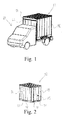
- the in Fig. 1 shown small truck 10 is detachably connected to a transport box 12.
- the transport box 12 can be separated, for example with the aid of a forklift from the truck 10, and replaced by another transport box 12.
- transport box 12 has both at an end face 14 and on a longitudinal side 16 openings 18 for receiving forks of a forklift.
- a door 19 is further provided so that operators can get into the interior of the transport box 12, for example, to invite transport items.
- the front side 14 may additionally or alternatively be provided with a flap and / or a roll-up door or the like.
- the transport box 12 has a housing 20 which has a flap 22 on an end face 14 opposite the door 19, which is hingedly connected by a hinge 24 to the housing 20 in a roof area with a frame.
- the flap 22 can be locked by a latch or a lock in the closed state.
- the housing 20 has a transport volume 26, in which a plurality of transport objects 28, for example, packages are arranged. In the transport volume and folding shelves can be provided, on which, for example, for delivering the transport items 28, a portion of the transport items 28 may be stored.
- tilted position of the transport box 12 reach the Transport objects via an outlet opening 30 formed between the flap 22 and the housing 20 from the transport volume 26 of the housing and are received by a conveyor belt 32.
- the transport items 28 can slide over a storage shelf 34 along a predefined Ausladewegs 36 to the exit opening 30.
- a guide element 38 which is a flexible material in the illustrated embodiment, the rigid weights 40, an unwanted movement along a predefined direction of movement 42 are inhibited. For example, it can be prevented that in a tilted position, the upper transport objects 28 fall to the exit opening 30. Instead, it is ensured that initially the lower transport objects 28 slide along the predefined Ausladewegs 36 on the Abladeboden 34 to the exit opening 30 and the upper transport objects 28 first reach the storage shelf 34 before they slip to the exit opening 30. Due to the weights 40, the guide element 38 presses sufficiently on the upper transport objects 28, so that the upper transport objects 28 can not move in the direction of an undesired predefined movement direction 42.
- a plurality of inflatable guide elements 38 are provided which fill the unnecessary transport volume 26 in the housing 20 and lock at least for the transport items 28. By the volume of the guide elements 38 movements of the transport items 28 are inhibited in the direction of movement 42 or even blocked.
- a plurality of guide elements 38 are combined to form a curtain 44.
- a plurality of guide elements 38 are movably connected to a support bar 46.
- the various guide elements 38 can be flat on the resting upper transport objects 28 and thereby inhibit or block movement in the direction of movement 42. This provides a resistor which inhibits upward movement or disables.
- the guide elements 38 may be configured inflatable.
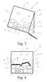
- the in Fig. 7 shown transport container 48 has a first chamber 50 and a second chamber 52, wherein the first chamber 50 and the second chamber 52 may each be configured as a transport box 12 as described above.
- the first chamber 50 has a boundary wall 54 facing the second chamber 52, through which a communication opening 56 between the chamber 50 and the second chamber 52 can be opened and closed.
- the boundary wall 54 is pivotally connected in a roof area with a frame of the first chamber 50 about a horizontal axis.
- the boundary wall 54 can swing open in particular in the tilted state of the transport container 48 by its own weight.
- the transport article 28 In the illustrated open state of the first chamber 50, the transport article 28 can slide along a predefined direction of movement 36 from the first chamber 50 into the second chamber 52.
- the boundary wall 54 may be designed flexible form, for example, by an elastomeric film is clamped on a rigid frame. Due to the shape-flexible design of the boundary wall 54, the movement of the transport article 28 can be braked by the boundary wall 54 without damaging the transport article 28.
- the boundary wall 54 extends to the shelf 34 of the first chamber 50 and the second chamber 52, so that stumbling for the transport article 28 are avoided in the movement from the first chamber 50 to the second chamber 52.
- the second chamber 52 also has a boundary wall 54 facing away from the first chamber 50 and positioned on the side of the second chamber 52 remote from the first chamber 50.
- the Boundary wall 54 of the second chamber 52 can also be a connection opening 56 is opened and closed.
- the transport container 48 may include a plurality of second chambers 52, which are each arranged side by side. It is possible to unload the transport objects 28 via the outlet opening 30 to be opened by the flap 22.
- the transport container 48 can be tilted about a first axis 60, so that the transport items 28 can be dumped on the longitudinal side of the transport container 48.
- transport articles 28 can be conveyed from the first chamber 50 to the second chamber 52 and thence to the next second chamber 52, respectively. If the transport objects have arrived in the last second chamber 52, the transport objects can be dumped via the boundary wall 54 on the front side of the transport container and / or via the outlet opening 30 of the last second chamber 52.
- the first chamber 50 and the second chambers 52 which are each formed in particular by the transport box 12, can be individually detachably connected to a common removable frame 62, so that the transport container 48, in particular as a swap body, can be transported by a tipper truck.
- the dump truck has in particular a hydraulic and / or pneumatic tilting device with the aid of which the transport container 48 can be tilted about the first axis 58 for unloading the transport articles 28.
- the transport container 48 can be decoupled together with the transport boxes 12 connected to the removable frame 62 as a common unit of a transport vehicle 10 and later tilted suitable with the help of a separate tilting device to dump the transport items 28 can.
- Damage to the transport items 28 may be prevented by the form-flexible boundary walls 54 and / or within the first chamber 50 and / or within the second chamber 52 arranged form-flexible guide elements 38 become.
- the transport container 48 can be coupled by the same transport vehicle or another transport vehicle and transported on.
Landscapes
- Engineering & Computer Science (AREA)
- Mechanical Engineering (AREA)
- Transportation (AREA)
- Loading Or Unloading Of Vehicles (AREA)
Applications Claiming Priority (1)
| Application Number | Priority Date | Filing Date | Title |
|---|---|---|---|
| DE200910017810 DE102009017810A1 (de) | 2009-04-20 | 2009-04-20 | Transportcontainer und Verfahren zum Entladen eines Transportcontainers |
Publications (2)
| Publication Number | Publication Date |
|---|---|
| EP2243726A1 true EP2243726A1 (fr) | 2010-10-27 |
| EP2243726B1 EP2243726B1 (fr) | 2013-09-25 |
Family
ID=42244635
Family Applications (1)
| Application Number | Title | Priority Date | Filing Date |
|---|---|---|---|
| EP20100160445 Active EP2243726B1 (fr) | 2009-04-20 | 2010-04-20 | Utilisation d'un conteneur de transport et procédé de décharge d'un tel conteneur de transport |
Country Status (3)
| Country | Link |
|---|---|
| EP (1) | EP2243726B1 (fr) |
| DE (1) | DE102009017810A1 (fr) |
| ES (1) | ES2433086T3 (fr) |
Cited By (1)
| Publication number | Priority date | Publication date | Assignee | Title |
|---|---|---|---|---|
| NL2005909C2 (nl) * | 2010-12-22 | 2012-06-27 | Ingbureaumoderniek B V | Inrichting voor het lossen van artikelen uit een bagagecontainer. |
Families Citing this family (2)
| Publication number | Priority date | Publication date | Assignee | Title |
|---|---|---|---|---|
| DE102010060310B4 (de) * | 2010-11-02 | 2012-05-16 | Red Parcel Post Ag | Transportbox |
| CN115159172B (zh) * | 2021-11-10 | 2025-12-02 | 杭州中水机器人制造有限公司 | 一种厢内输送装置 |
Citations (10)
| Publication number | Priority date | Publication date | Assignee | Title |
|---|---|---|---|---|
| DE1964772A1 (de) * | 1969-12-24 | 1971-07-15 | Waggon Und Maschb Ag Donauwoer | Vorrichtung zum Verzurren einer Ladung |
| GB1390518A (en) * | 1971-11-04 | 1975-04-16 | Mitsubishi Chem Ind | Containers for transporting goods |
| DE3232229A1 (de) * | 1982-08-30 | 1984-03-15 | Normann 2808 Syke Bock | Behaelter fuer schuettgut, insbesondere muell |
| US5326212A (en) * | 1989-01-12 | 1994-07-05 | Roberts Hardy G | Sectional van trailer having detachable, interchangeable compartments capable of forming a continuous van body |
| EP0652132A1 (fr) | 1993-11-04 | 1995-05-10 | RKB-Reparatur und Karosseriebau GmbH | Véhicule à moteur pour le transport de conteneurs échangeables |
| JP2001261105A (ja) * | 2000-03-24 | 2001-09-26 | Hiroshi Abe | 廃棄物用分別コンテナ |
| JP2002104580A (ja) * | 2000-10-04 | 2002-04-10 | Ashimori Ind Co Ltd | 冷凍車又は冷蔵車庫内の中仕切り壁及び中仕切り装置 |
| US6537003B1 (en) * | 2000-08-21 | 2003-03-25 | Michael David Rostoker | Load restraint system and method |
| US7114909B2 (en) | 2002-11-25 | 2006-10-03 | Ty-Crop Manufacturing, Ltd. | Trailer-tilting, load-discharge apparatus and method |
| US20080056839A1 (en) * | 2006-09-01 | 2008-03-06 | Mark Edmund Maresh | Apparatus and Method for Protecting Products from Damage During Shipment |
Family Cites Families (5)
| Publication number | Priority date | Publication date | Assignee | Title |
|---|---|---|---|---|
| GB582780A (en) * | 1944-07-04 | 1946-11-27 | Derbyshire Stone Ltd | Improvements in or relating to apparatus for feeding granular material |
| DE2217427A1 (de) * | 1972-04-12 | 1973-10-31 | Riechelmann Harry | Schuettgut-container mit verladegeraeten |
| DE4303349C1 (de) * | 1993-02-05 | 1994-05-19 | Gert Richter | Transportvorrichtung für die Wertstoffentsorgung |
| DE19652817C1 (de) * | 1996-08-12 | 1997-10-09 | Horst Neufingerl | Bausatz zum starren Verbinden zweier an ihren Ecken mit hohlen Eckbeschlägen versehenen Containern sowie Handhabungswerkzeug |
| DE10326619A1 (de) * | 2003-06-13 | 2005-01-13 | Gerd Kellershohn | Container zur Aufnahme von Stück- oder Schüttgut |
-
2009
- 2009-04-20 DE DE200910017810 patent/DE102009017810A1/de not_active Withdrawn
-
2010
- 2010-04-20 EP EP20100160445 patent/EP2243726B1/fr active Active
- 2010-04-20 ES ES10160445T patent/ES2433086T3/es active Active
Patent Citations (10)
| Publication number | Priority date | Publication date | Assignee | Title |
|---|---|---|---|---|
| DE1964772A1 (de) * | 1969-12-24 | 1971-07-15 | Waggon Und Maschb Ag Donauwoer | Vorrichtung zum Verzurren einer Ladung |
| GB1390518A (en) * | 1971-11-04 | 1975-04-16 | Mitsubishi Chem Ind | Containers for transporting goods |
| DE3232229A1 (de) * | 1982-08-30 | 1984-03-15 | Normann 2808 Syke Bock | Behaelter fuer schuettgut, insbesondere muell |
| US5326212A (en) * | 1989-01-12 | 1994-07-05 | Roberts Hardy G | Sectional van trailer having detachable, interchangeable compartments capable of forming a continuous van body |
| EP0652132A1 (fr) | 1993-11-04 | 1995-05-10 | RKB-Reparatur und Karosseriebau GmbH | Véhicule à moteur pour le transport de conteneurs échangeables |
| JP2001261105A (ja) * | 2000-03-24 | 2001-09-26 | Hiroshi Abe | 廃棄物用分別コンテナ |
| US6537003B1 (en) * | 2000-08-21 | 2003-03-25 | Michael David Rostoker | Load restraint system and method |
| JP2002104580A (ja) * | 2000-10-04 | 2002-04-10 | Ashimori Ind Co Ltd | 冷凍車又は冷蔵車庫内の中仕切り壁及び中仕切り装置 |
| US7114909B2 (en) | 2002-11-25 | 2006-10-03 | Ty-Crop Manufacturing, Ltd. | Trailer-tilting, load-discharge apparatus and method |
| US20080056839A1 (en) * | 2006-09-01 | 2008-03-06 | Mark Edmund Maresh | Apparatus and Method for Protecting Products from Damage During Shipment |
Cited By (1)
| Publication number | Priority date | Publication date | Assignee | Title |
|---|---|---|---|---|
| NL2005909C2 (nl) * | 2010-12-22 | 2012-06-27 | Ingbureaumoderniek B V | Inrichting voor het lossen van artikelen uit een bagagecontainer. |
Also Published As
| Publication number | Publication date |
|---|---|
| ES2433086T3 (es) | 2013-12-09 |
| DE102009017810A1 (de) | 2010-10-21 |
| EP2243726B1 (fr) | 2013-09-25 |
Similar Documents
| Publication | Publication Date | Title |
|---|---|---|
| EP3774601B1 (fr) | Poste de déchargement et procédé destiné au déchargement d'un récipient de produit à transporter chargé avec un produit à transporter | |
| EP2152617B1 (fr) | Dispositif et procédé pour décharger des articles situés dans un contenant | |
| EP0873262B1 (fr) | Dispositif de transport pour pieces individuelles | |
| EP2958838B1 (fr) | Dispositif et procédé de transport d'objets | |
| DE10246285B4 (de) | Anordnung und Verfahren zum Beladen eines Laderaumes mit Stückgütern | |
| DE102020126448B4 (de) | Verfahren und Vorrichtung zum Beladen von Behältern mit Packstücken | |
| WO2013017538A1 (fr) | Dispositif et procédé pour charger une unité de transport | |
| EP3080021B1 (fr) | Dispositif et procédé permettant de manipuler des objets | |
| EP2281762B1 (fr) | Procédé de déchargement d'une pluralité de produits et dispositif de déchargement | |
| EP2450112B1 (fr) | Procédé et appareil pour charger des marchandises dans un conteneur de transport | |
| EP3418227B1 (fr) | Robot transporteur sur rail et procédé de fonctionnement d'un robot transporteur sur rail | |
| EP2243726B1 (fr) | Utilisation d'un conteneur de transport et procédé de décharge d'un tel conteneur de transport | |
| WO2015173040A1 (fr) | Poste de transfert permettant le transfert de marchandises au détail entre un véhicule et un support | |
| DE102011002710A1 (de) | Entladevorrichtung | |
| DE102015217665A1 (de) | Vorrichtung zum Fördern zumindest eines Ladungsträgers und Verfahren zum Betreiben einer derartigen Vorrichtung | |
| AT13398U1 (de) | Vertikaler schachtförderer und -stapler | |
| DE102017111609B3 (de) | Nutzfahrzeug mit beweglicher Ladeplattform | |
| DE102008059311B4 (de) | Transportbox und Verfahren zum Entladen einer Transportbox | |
| EP2188194A1 (fr) | Récipient de transport avec système de transport; procédé pour décharger des récipients de transport | |
| EP2447189B1 (fr) | Boîte de transport et procédé de déchargement de produits en vrac | |
| EP1839988A2 (fr) | Dispositif pour basculer un containeur monté sur un wagon | |
| DE19817255C1 (de) | Träger zum Transport von Werkstücken | |
| DE202007003582U1 (de) | Kippeinrichtung | |
| DE102006031124B3 (de) | Stoffeingabe einer Sendungsvereinzelungsanlage | |
| DE2252584C3 (de) | Hochlager für In Kolli verpackte Güter |
Legal Events
| Date | Code | Title | Description |
|---|---|---|---|
| PUAI | Public reference made under article 153(3) epc to a published international application that has entered the european phase |
Free format text: ORIGINAL CODE: 0009012 |
|
| AK | Designated contracting states |
Kind code of ref document: A1 Designated state(s): AT BE BG CH CY CZ DE DK EE ES FI FR GB GR HR HU IE IS IT LI LT LU LV MC MK MT NL NO PL PT RO SE SI SK SM TR |
|
| AX | Request for extension of the european patent |
Extension state: AL BA ME RS |
|
| 17P | Request for examination filed |
Effective date: 20110414 |
|
| 17Q | First examination report despatched |
Effective date: 20111103 |
|
| REG | Reference to a national code |
Ref country code: DE Ref legal event code: R079 Ref document number: 502010004844 Country of ref document: DE Free format text: PREVIOUS MAIN CLASS: B65D0088560000 Ipc: B60P0007060000 |
|
| RIC1 | Information provided on ipc code assigned before grant |
Ipc: B65D 88/56 20060101ALI20121129BHEP Ipc: B60P 7/08 20060101ALI20121129BHEP Ipc: B60P 7/06 20060101AFI20121129BHEP Ipc: B65D 90/00 20060101ALI20121129BHEP |
|
| GRAP | Despatch of communication of intention to grant a patent |
Free format text: ORIGINAL CODE: EPIDOSNIGR1 |
|
| RIN1 | Information on inventor provided before grant (corrected) |
Inventor name: HELLMICH, WALTER |
|
| GRAP | Despatch of communication of intention to grant a patent |
Free format text: ORIGINAL CODE: EPIDOSNIGR1 |
|
| INTG | Intention to grant announced |
Effective date: 20130415 |
|
| GRAS | Grant fee paid |
Free format text: ORIGINAL CODE: EPIDOSNIGR3 |
|
| GRAA | (expected) grant |
Free format text: ORIGINAL CODE: 0009210 |
|
| AK | Designated contracting states |
Kind code of ref document: B1 Designated state(s): AT BE BG CH CY CZ DE DK EE ES FI FR GB GR HR HU IE IS IT LI LT LU LV MC MK MT NL NO PL PT RO SE SI SK SM TR |
|
| REG | Reference to a national code |
Ref country code: GB Ref legal event code: FG4D Free format text: NOT ENGLISH |
|
| REG | Reference to a national code |
Ref country code: CH Ref legal event code: EP |
|
| REG | Reference to a national code |
Ref country code: AT Ref legal event code: REF Ref document number: 633573 Country of ref document: AT Kind code of ref document: T Effective date: 20131015 |
|
| REG | Reference to a national code |
Ref country code: IE Ref legal event code: FG4D Free format text: LANGUAGE OF EP DOCUMENT: GERMAN |
|
| REG | Reference to a national code |
Ref country code: DE Ref legal event code: R096 Ref document number: 502010004844 Country of ref document: DE Effective date: 20131121 |
|
| REG | Reference to a national code |
Ref country code: ES Ref legal event code: FG2A Ref document number: 2433086 Country of ref document: ES Kind code of ref document: T3 Effective date: 20131209 |
|
| PG25 | Lapsed in a contracting state [announced via postgrant information from national office to epo] |
Ref country code: NO Free format text: LAPSE BECAUSE OF FAILURE TO SUBMIT A TRANSLATION OF THE DESCRIPTION OR TO PAY THE FEE WITHIN THE PRESCRIBED TIME-LIMIT Effective date: 20131225 Ref country code: SE Free format text: LAPSE BECAUSE OF FAILURE TO SUBMIT A TRANSLATION OF THE DESCRIPTION OR TO PAY THE FEE WITHIN THE PRESCRIBED TIME-LIMIT Effective date: 20130925 Ref country code: HR Free format text: LAPSE BECAUSE OF FAILURE TO SUBMIT A TRANSLATION OF THE DESCRIPTION OR TO PAY THE FEE WITHIN THE PRESCRIBED TIME-LIMIT Effective date: 20130925 Ref country code: LT Free format text: LAPSE BECAUSE OF FAILURE TO SUBMIT A TRANSLATION OF THE DESCRIPTION OR TO PAY THE FEE WITHIN THE PRESCRIBED TIME-LIMIT Effective date: 20130925 |
|
| REG | Reference to a national code |
Ref country code: NL Ref legal event code: VDEP Effective date: 20130925 |
|
| REG | Reference to a national code |
Ref country code: LT Ref legal event code: MG4D |
|
| PG25 | Lapsed in a contracting state [announced via postgrant information from national office to epo] |
Ref country code: LV Free format text: LAPSE BECAUSE OF FAILURE TO SUBMIT A TRANSLATION OF THE DESCRIPTION OR TO PAY THE FEE WITHIN THE PRESCRIBED TIME-LIMIT Effective date: 20130925 Ref country code: SI Free format text: LAPSE BECAUSE OF FAILURE TO SUBMIT A TRANSLATION OF THE DESCRIPTION OR TO PAY THE FEE WITHIN THE PRESCRIBED TIME-LIMIT Effective date: 20130925 Ref country code: FI Free format text: LAPSE BECAUSE OF FAILURE TO SUBMIT A TRANSLATION OF THE DESCRIPTION OR TO PAY THE FEE WITHIN THE PRESCRIBED TIME-LIMIT Effective date: 20130925 Ref country code: GR Free format text: LAPSE BECAUSE OF FAILURE TO SUBMIT A TRANSLATION OF THE DESCRIPTION OR TO PAY THE FEE WITHIN THE PRESCRIBED TIME-LIMIT Effective date: 20131226 |
|
| PG25 | Lapsed in a contracting state [announced via postgrant information from national office to epo] |
Ref country code: IS Free format text: LAPSE BECAUSE OF FAILURE TO SUBMIT A TRANSLATION OF THE DESCRIPTION OR TO PAY THE FEE WITHIN THE PRESCRIBED TIME-LIMIT Effective date: 20140125 Ref country code: EE Free format text: LAPSE BECAUSE OF FAILURE TO SUBMIT A TRANSLATION OF THE DESCRIPTION OR TO PAY THE FEE WITHIN THE PRESCRIBED TIME-LIMIT Effective date: 20130925 Ref country code: SK Free format text: LAPSE BECAUSE OF FAILURE TO SUBMIT A TRANSLATION OF THE DESCRIPTION OR TO PAY THE FEE WITHIN THE PRESCRIBED TIME-LIMIT Effective date: 20130925 Ref country code: NL Free format text: LAPSE BECAUSE OF FAILURE TO SUBMIT A TRANSLATION OF THE DESCRIPTION OR TO PAY THE FEE WITHIN THE PRESCRIBED TIME-LIMIT Effective date: 20130925 Ref country code: RO Free format text: LAPSE BECAUSE OF FAILURE TO SUBMIT A TRANSLATION OF THE DESCRIPTION OR TO PAY THE FEE WITHIN THE PRESCRIBED TIME-LIMIT Effective date: 20130925 Ref country code: CZ Free format text: LAPSE BECAUSE OF FAILURE TO SUBMIT A TRANSLATION OF THE DESCRIPTION OR TO PAY THE FEE WITHIN THE PRESCRIBED TIME-LIMIT Effective date: 20130925 |
|
| PG25 | Lapsed in a contracting state [announced via postgrant information from national office to epo] |
Ref country code: CY Free format text: LAPSE BECAUSE OF FAILURE TO SUBMIT A TRANSLATION OF THE DESCRIPTION OR TO PAY THE FEE WITHIN THE PRESCRIBED TIME-LIMIT Effective date: 20130925 Ref country code: PL Free format text: LAPSE BECAUSE OF FAILURE TO SUBMIT A TRANSLATION OF THE DESCRIPTION OR TO PAY THE FEE WITHIN THE PRESCRIBED TIME-LIMIT Effective date: 20130925 |
|
| REG | Reference to a national code |
Ref country code: DE Ref legal event code: R097 Ref document number: 502010004844 Country of ref document: DE |
|
| PG25 | Lapsed in a contracting state [announced via postgrant information from national office to epo] |
Ref country code: PT Free format text: LAPSE BECAUSE OF FAILURE TO SUBMIT A TRANSLATION OF THE DESCRIPTION OR TO PAY THE FEE WITHIN THE PRESCRIBED TIME-LIMIT Effective date: 20140127 |
|
| PLBE | No opposition filed within time limit |
Free format text: ORIGINAL CODE: 0009261 |
|
| STAA | Information on the status of an ep patent application or granted ep patent |
Free format text: STATUS: NO OPPOSITION FILED WITHIN TIME LIMIT |
|
| PG25 | Lapsed in a contracting state [announced via postgrant information from national office to epo] |
Ref country code: IT Free format text: LAPSE BECAUSE OF FAILURE TO SUBMIT A TRANSLATION OF THE DESCRIPTION OR TO PAY THE FEE WITHIN THE PRESCRIBED TIME-LIMIT Effective date: 20130925 |
|
| 26N | No opposition filed |
Effective date: 20140626 |
|
| PG25 | Lapsed in a contracting state [announced via postgrant information from national office to epo] |
Ref country code: DK Free format text: LAPSE BECAUSE OF FAILURE TO SUBMIT A TRANSLATION OF THE DESCRIPTION OR TO PAY THE FEE WITHIN THE PRESCRIBED TIME-LIMIT Effective date: 20130925 |
|
| REG | Reference to a national code |
Ref country code: DE Ref legal event code: R097 Ref document number: 502010004844 Country of ref document: DE Effective date: 20140626 |
|
| PG25 | Lapsed in a contracting state [announced via postgrant information from national office to epo] |
Ref country code: LU Free format text: LAPSE BECAUSE OF FAILURE TO SUBMIT A TRANSLATION OF THE DESCRIPTION OR TO PAY THE FEE WITHIN THE PRESCRIBED TIME-LIMIT Effective date: 20140420 Ref country code: MC Free format text: LAPSE BECAUSE OF FAILURE TO SUBMIT A TRANSLATION OF THE DESCRIPTION OR TO PAY THE FEE WITHIN THE PRESCRIBED TIME-LIMIT Effective date: 20130925 |
|
| GBPC | Gb: european patent ceased through non-payment of renewal fee |
Effective date: 20140420 |
|
| REG | Reference to a national code |
Ref country code: IE Ref legal event code: MM4A |
|
| PG25 | Lapsed in a contracting state [announced via postgrant information from national office to epo] |
Ref country code: GB Free format text: LAPSE BECAUSE OF NON-PAYMENT OF DUE FEES Effective date: 20140420 |
|
| PG25 | Lapsed in a contracting state [announced via postgrant information from national office to epo] |
Ref country code: IE Free format text: LAPSE BECAUSE OF NON-PAYMENT OF DUE FEES Effective date: 20140420 |
|
| PG25 | Lapsed in a contracting state [announced via postgrant information from national office to epo] |
Ref country code: MT Free format text: LAPSE BECAUSE OF FAILURE TO SUBMIT A TRANSLATION OF THE DESCRIPTION OR TO PAY THE FEE WITHIN THE PRESCRIBED TIME-LIMIT Effective date: 20130925 |
|
| REG | Reference to a national code |
Ref country code: FR Ref legal event code: PLFP Year of fee payment: 7 |
|
| PG25 | Lapsed in a contracting state [announced via postgrant information from national office to epo] |
Ref country code: SM Free format text: LAPSE BECAUSE OF FAILURE TO SUBMIT A TRANSLATION OF THE DESCRIPTION OR TO PAY THE FEE WITHIN THE PRESCRIBED TIME-LIMIT Effective date: 20130925 |
|
| PG25 | Lapsed in a contracting state [announced via postgrant information from national office to epo] |
Ref country code: BG Free format text: LAPSE BECAUSE OF FAILURE TO SUBMIT A TRANSLATION OF THE DESCRIPTION OR TO PAY THE FEE WITHIN THE PRESCRIBED TIME-LIMIT Effective date: 20130925 |
|
| PG25 | Lapsed in a contracting state [announced via postgrant information from national office to epo] |
Ref country code: TR Free format text: LAPSE BECAUSE OF FAILURE TO SUBMIT A TRANSLATION OF THE DESCRIPTION OR TO PAY THE FEE WITHIN THE PRESCRIBED TIME-LIMIT Effective date: 20130925 Ref country code: HU Free format text: LAPSE BECAUSE OF FAILURE TO SUBMIT A TRANSLATION OF THE DESCRIPTION OR TO PAY THE FEE WITHIN THE PRESCRIBED TIME-LIMIT; INVALID AB INITIO Effective date: 20100420 Ref country code: BE Free format text: LAPSE BECAUSE OF FAILURE TO SUBMIT A TRANSLATION OF THE DESCRIPTION OR TO PAY THE FEE WITHIN THE PRESCRIBED TIME-LIMIT Effective date: 20140430 |
|
| REG | Reference to a national code |
Ref country code: FR Ref legal event code: PLFP Year of fee payment: 8 |
|
| REG | Reference to a national code |
Ref country code: FR Ref legal event code: PLFP Year of fee payment: 9 |
|
| PG25 | Lapsed in a contracting state [announced via postgrant information from national office to epo] |
Ref country code: MK Free format text: LAPSE BECAUSE OF FAILURE TO SUBMIT A TRANSLATION OF THE DESCRIPTION OR TO PAY THE FEE WITHIN THE PRESCRIBED TIME-LIMIT Effective date: 20130925 |
|
| PGFP | Annual fee paid to national office [announced via postgrant information from national office to epo] |
Ref country code: DE Payment date: 20250429 Year of fee payment: 16 |
|
| PGFP | Annual fee paid to national office [announced via postgrant information from national office to epo] |
Ref country code: ES Payment date: 20250529 Year of fee payment: 16 |
|
| PGFP | Annual fee paid to national office [announced via postgrant information from national office to epo] |
Ref country code: FR Payment date: 20250424 Year of fee payment: 16 |
|
| PGFP | Annual fee paid to national office [announced via postgrant information from national office to epo] |
Ref country code: CH Payment date: 20250501 Year of fee payment: 16 |
|
| PGFP | Annual fee paid to national office [announced via postgrant information from national office to epo] |
Ref country code: AT Payment date: 20250423 Year of fee payment: 16 |