EP2243880A2 - Eclisse isolante pour un joint d'isolement - Google Patents
Eclisse isolante pour un joint d'isolement Download PDFInfo
- Publication number
- EP2243880A2 EP2243880A2 EP10002836A EP10002836A EP2243880A2 EP 2243880 A2 EP2243880 A2 EP 2243880A2 EP 10002836 A EP10002836 A EP 10002836A EP 10002836 A EP10002836 A EP 10002836A EP 2243880 A2 EP2243880 A2 EP 2243880A2
- Authority
- EP
- European Patent Office
- Prior art keywords
- rail
- protective shells
- rail ends
- insulating
- region
- Prior art date
- Legal status (The legal status is an assumption and is not a legal conclusion. Google has not performed a legal analysis and makes no representation as to the accuracy of the status listed.)
- Withdrawn
Links
- 230000001681 protective effect Effects 0.000 claims abstract description 27
- 239000012777 electrically insulating material Substances 0.000 claims abstract description 4
- 229910000831 Steel Inorganic materials 0.000 description 6
- 239000010959 steel Substances 0.000 description 6
- 239000010410 layer Substances 0.000 description 5
- 239000002313 adhesive film Substances 0.000 description 4
- 238000005553 drilling Methods 0.000 description 3
- 230000000149 penetrating effect Effects 0.000 description 3
- 239000012790 adhesive layer Substances 0.000 description 2
- 239000003365 glass fiber Substances 0.000 description 2
- 238000005452 bending Methods 0.000 description 1
- 230000000694 effects Effects 0.000 description 1
- 238000009434 installation Methods 0.000 description 1
- 238000009413 insulation Methods 0.000 description 1
- 238000004519 manufacturing process Methods 0.000 description 1
- 239000012811 non-conductive material Substances 0.000 description 1
- 238000004513 sizing Methods 0.000 description 1
- 125000006850 spacer group Chemical group 0.000 description 1
Images
Classifications
-
- E—FIXED CONSTRUCTIONS
- E01—CONSTRUCTION OF ROADS, RAILWAYS, OR BRIDGES
- E01B—PERMANENT WAY; PERMANENT-WAY TOOLS; MACHINES FOR MAKING RAILWAYS OF ALL KINDS
- E01B11/00—Rail joints
- E01B11/54—Electrically-insulating rail joints
Definitions
- the invention relates to an insulating strip according to the features of the preamble of claim 1.
- the one from the document DE 20 09 175 known Isolier conjunction is in contrast by a steel existing, the parting line bridging Isolierlasche, which is provided with an intermediate layer of insulation on the track side interrupted in the region of the parting protective shells made of sheet steel, continuous holes in the tab and the rail ends are filled with insulating sleeves, so that a is given to the rails electrically insulated arrangement of the recorded in these holes screws.
- the parting line bridging Isolierlasche which is provided with an intermediate layer of insulation on the track side interrupted in the region of the parting protective shells made of sheet steel, continuous holes in the tab and the rail ends are filled with insulating sleeves, so that a is given to the rails electrically insulated arrangement of the recorded in these holes screws.
- a Isolierfar of the kind presented in these two documents is by a perpendicular to the rail longitudinal direction extending continuous Parting line between the rail ends, so that in the case of Isolierstosses according to the document DE 20 09 175 on both sides of the rails same protective shells are used.
- U. a. To reduce the resulting from the rollover of such a parting line noise and the associated wear rail joints and insulating joints have been developed in which a parting line in a first section starting from the running surface of the rail head initially about half of the rail height vertically, but at an angle to the rail longitudinal direction, z. B. extends from 30 °, wherein the second, the rail foot penetrating portion in turn extends perpendicular to the rail longitudinal direction.
- the so definable sections of the parting line ends at their mutually facing areas in a continuous, but longitudinally divided bore, wherein an adapted to this joint geometry insulating body, while filling the bore, is inserted into the parting line.
- Essential to the invention is hereafter a symmetrical with respect to a vertical transverse center plane between the rail ends sizing the boundaries of the protective shells, as far as a minimum distance between them is concerned.
- Said transverse center plane denotes such a plane whose track, perpendicular to the longitudinal direction of the rail, describes an axis of symmetry with respect to a surface which is parallel to the projection of the inclined surfaces of the rail ends in a plane Rail length direction corresponds. Because of this symmetry property so equipped Isolierlasche can be used on both sides of the rail ends, so that when working in the laid track a holding of two tab types, namely for right- or left-side mounting unnecessary. As far as the symmetry property is respected for the minimum distance, the boundaries can in principle be designed in accordance with any curve.
- the boundaries of the protective shells in the form of bevels form in the region of the parting line.
- claims 3 and 4 are directed to further advantageous embodiments. It is thus a finished, that is directly usable insulating provided, which has a substantially smooth surface on the rail side due to said insert.
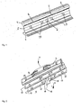
- Fig. 1 shows two by a parting line 1 frontally spaced rail ends 2, 3 before the installation of insulating tabs.
- the parting line 1 is applied in the manner of an oblique impact, that is, it extends in an upper first, the rail head 4 penetrating and in a central region of the web 5 in a Bore 6 ends at an angle of about 30 ° to the rail longitudinal direction and in a second, adjoining said bore, the rail foot 7 penetrating portion transverse to the rail longitudinal direction.
- the bore 6 is thus formed longitudinally divided due to the parting line 1.
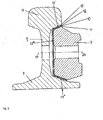
- Isolierlasche 8 consists of a steel plate body 9, which is geometrically on its, the rail ends facing side to rest against facing inclined surfaces of the rail head 4 and the rail foot 7 is set up, with interposition of an existing example of a hard tissue insulating layer 10 over an outer adhesive film 11 is glued to the tab body 9 and an inner adhesive film 12 with protective shells 13.
- the protective shells 13 are made of sheet steel and have an approximately U-shaped cross section, the side legs 13 ', 13 "are intended for direct contact with the opposite sections of the rail head 4 and the rail foot 7.
- the base portion 13"' of this U -shaped profile extends approximately vertically.
- the insulating layer 10 is continuous, that is, the parting line 1 bridging formed in particular in the region of the oblique impact.
- Fig. 2 can recognize the two protective shells 13 are provided on their sides facing each other with respect to a vertical transverse center plane 14-14 symmetrical continuous chamfers 15, between which a starting from a bottom 16 to a top continuous increase in the distance between the end faces of each other in the Area of the parting line 1 on one side of the rail ends 2, 3 opposing protective shells 13 results.
- the protective shells 13 extending chamfer 15 may be in the range of the side legs 13', 13" continuously continued. However, it can also, as in Fig. 2 by way of example for the upper side legs 13 'shown, in accordance with a greater bending, the distance between the end faces of the two protective shells 13 may be formed enlarged.
- the extent of the chamfers 15 is dimensioned to the effect that in this sense equipped completely identical insulating tabs 8 on both sides of the rail ends 2, 3 can be used. This requires only that advance that it is ensured that, in particular in the upper region, that is, in the region above the bore 6, namely the actual oblique impact, the distance of the opposite end faces of the two protective shells 13 is set up such that despite the Rail longitudinal direction given skew the front sides of the rail ends 2, 3, the insulating property of the insulating 8 is secured, that is, a protective shell 13 is in each case with only one rail end 2, 3 in metallic contact.
- Zeichnerisch not shown is a geometrically adapted to the shape of the parting line 1 including the bore 6, inserted into the parting line 1, electrically insulating effective separating body.
- Zeichnerisch also not shown are made of an electrically insulating material existing, in the holes 19 of the rail ends 2, 3 and aligned with these holes 20 of the tab body 9, the insulating layer 10 and the protective shells 13 Isoliermuffen to be inserted, which an electrically isolated recording of in to use these holes, the attachment of the insulating 8 on both sides of the rail ends 2, 3 and thus allow the production of a Isolierconcees serving screws.
Landscapes
- Engineering & Computer Science (AREA)
- Mechanical Engineering (AREA)
- Architecture (AREA)
- Civil Engineering (AREA)
- Structural Engineering (AREA)
- Insulating Bodies (AREA)
- Distribution Board (AREA)
- Machines For Laying And Maintaining Railways (AREA)
Applications Claiming Priority (1)
| Application Number | Priority Date | Filing Date | Title |
|---|---|---|---|
| DE200920005846 DE202009005846U1 (de) | 2009-04-21 | 2009-04-21 | Isolierlasche für einen Isolierstoß |
Publications (2)
| Publication Number | Publication Date |
|---|---|
| EP2243880A2 true EP2243880A2 (fr) | 2010-10-27 |
| EP2243880A3 EP2243880A3 (fr) | 2013-03-13 |
Family
ID=40786425
Family Applications (1)
| Application Number | Title | Priority Date | Filing Date |
|---|---|---|---|
| EP10002836A Withdrawn EP2243880A3 (fr) | 2009-04-21 | 2010-03-18 | Eclisse isolante pour un joint d'isolement |
Country Status (2)
| Country | Link |
|---|---|
| EP (1) | EP2243880A3 (fr) |
| DE (1) | DE202009005846U1 (fr) |
Cited By (3)
| Publication number | Priority date | Publication date | Assignee | Title |
|---|---|---|---|---|
| US20190127923A1 (en) * | 2017-10-31 | 2019-05-02 | Koppers Delaware, Inc. | Rail Joint Assembly having Forged Rail Joint Bars |
| EA038873B1 (ru) * | 2020-07-17 | 2021-10-29 | Общество с ограниченной ответственностью "БелФормКомпозит" | Металлополимерная накладка для сборного изолирующего стыка рельсов |
| CN117230666A (zh) * | 2023-11-02 | 2023-12-15 | 铁科(北京)轨道装备技术有限公司 | 钢轨厂内胶接绝缘接头制备工艺 |
Citations (2)
| Publication number | Priority date | Publication date | Assignee | Title |
|---|---|---|---|---|
| DE2009175A1 (de) | 1970-02-27 | 1971-09-16 | Elektro Thermit Gmbh | Isolierlasche |
| US5503331A (en) | 1994-05-20 | 1996-04-02 | Portec-Rmp Division | Insulated rail joint incorporating spacer-impregnated adhesive and method for bonding insulated rail joints |
Family Cites Families (1)
| Publication number | Priority date | Publication date | Assignee | Title |
|---|---|---|---|---|
| DE202005005871U1 (de) * | 2005-03-09 | 2005-08-11 | Bwg Gmbh & Co. Kg | Stoßstellenbereich sowie Lasche |
-
2009
- 2009-04-21 DE DE200920005846 patent/DE202009005846U1/de not_active Expired - Lifetime
-
2010
- 2010-03-18 EP EP10002836A patent/EP2243880A3/fr not_active Withdrawn
Patent Citations (2)
| Publication number | Priority date | Publication date | Assignee | Title |
|---|---|---|---|---|
| DE2009175A1 (de) | 1970-02-27 | 1971-09-16 | Elektro Thermit Gmbh | Isolierlasche |
| US5503331A (en) | 1994-05-20 | 1996-04-02 | Portec-Rmp Division | Insulated rail joint incorporating spacer-impregnated adhesive and method for bonding insulated rail joints |
Cited By (5)
| Publication number | Priority date | Publication date | Assignee | Title |
|---|---|---|---|---|
| US20190127923A1 (en) * | 2017-10-31 | 2019-05-02 | Koppers Delaware, Inc. | Rail Joint Assembly having Forged Rail Joint Bars |
| WO2019089532A1 (fr) * | 2017-10-31 | 2019-05-09 | Koppers Delaware, Inc. | Ensemble joint de rail ayant des barres de joint de rail forgées |
| US10961665B2 (en) | 2017-10-31 | 2021-03-30 | Koppers Delaware, Inc. | Rail joint assembly having forged rail joint bars |
| EA038873B1 (ru) * | 2020-07-17 | 2021-10-29 | Общество с ограниченной ответственностью "БелФормКомпозит" | Металлополимерная накладка для сборного изолирующего стыка рельсов |
| CN117230666A (zh) * | 2023-11-02 | 2023-12-15 | 铁科(北京)轨道装备技术有限公司 | 钢轨厂内胶接绝缘接头制备工艺 |
Also Published As
| Publication number | Publication date |
|---|---|
| DE202009005846U1 (de) | 2009-06-18 |
| EP2243880A3 (fr) | 2013-03-13 |
Similar Documents
| Publication | Publication Date | Title |
|---|---|---|
| EP1980361B1 (fr) | Elément de raccordement et revêtement de protection | |
| DE3518990C2 (de) | Führungsschiene für eine Kettensäge | |
| EP2476853B1 (fr) | Profil composite pour fenêtres, portes et façades et son procédé de fabrication | |
| EP2931553B1 (fr) | Rail d'alimentation | |
| DE102010007081A1 (de) | Gewichtsreduzierte Führungsschiene aus Vollmaterial | |
| DE102013221175B4 (de) | Winkelführungsplatte | |
| EP2819879A2 (fr) | Support isolant pour un rail conducteur pour des véhicules ferroviaires à entraînement électrique | |
| DE102011052110A1 (de) | Leichtblechkonstruktion | |
| WO2008064692A1 (fr) | Panneau de plancher avec rainure et languette | |
| DE202009005846U1 (de) | Isolierlasche für einen Isolierstoß | |
| DE202009008981U1 (de) | Geschossfangvorrichtung | |
| DE20317180U1 (de) | Lärmschutzelement und Lärmschutzwand | |
| EP0153463A2 (fr) | Elément de plaque en profilés creux | |
| DE202012103447U1 (de) | Rollenlaufschiene für einen Kamerawagen | |
| DE102011011633A1 (de) | Abstützvorrichtung für einen Schienenfahrzeug-Fußboden | |
| DE102015117544A1 (de) | "Glashalter" | |
| CH652165A5 (de) | Insbesondere fuer garagentore bestimmte zarge mit befestigungs-vorrichtung. | |
| DE102008059152A1 (de) | Verbindungsknoten für ein Fahrzeug | |
| EP2474409A1 (fr) | Liaison entre un composant de base et un élément composite multicouche renforcé par des fibres | |
| DE4311497C2 (de) | Ebenes, aus Strangpreßprofilen gebildetes, doppelwandiges Verbundprofil | |
| DE2951570A1 (de) | Isolierstoss fuer eisenbahngleis | |
| DE102008062222A1 (de) | Kraftfahrzeug mit einem aus Kunststoff bestehenden Außenhautbauteil | |
| DE202023105321U1 (de) | Schutzabdeckung | |
| DE102022109744A1 (de) | Herzstück einer schienenweiche | |
| DE20008067U1 (de) | Flächiges Verbundbauteil |
Legal Events
| Date | Code | Title | Description |
|---|---|---|---|
| PUAI | Public reference made under article 153(3) epc to a published international application that has entered the european phase |
Free format text: ORIGINAL CODE: 0009012 |
|
| AK | Designated contracting states |
Kind code of ref document: A2 Designated state(s): AT BE BG CH CY CZ DE DK EE ES FI FR GB GR HR HU IE IS IT LI LT LU LV MC MK MT NL NO PL PT RO SE SI SK SM TR |
|
| AX | Request for extension of the european patent |
Extension state: AL BA ME RS |
|
| PUAL | Search report despatched |
Free format text: ORIGINAL CODE: 0009013 |
|
| AK | Designated contracting states |
Kind code of ref document: A3 Designated state(s): AT BE BG CH CY CZ DE DK EE ES FI FR GB GR HR HU IE IS IT LI LT LU LV MC MK MT NL NO PL PT RO SE SI SK SM TR |
|
| AX | Request for extension of the european patent |
Extension state: AL BA ME RS |
|
| RIC1 | Information provided on ipc code assigned before grant |
Ipc: E01B 11/24 20060101ALI20130205BHEP Ipc: E01B 11/54 20060101AFI20130205BHEP |
|
| 17P | Request for examination filed |
Effective date: 20130905 |
|
| RBV | Designated contracting states (corrected) |
Designated state(s): AT BE BG CH CY CZ DE DK EE ES FI FR GB GR HR HU IE IS IT LI LT LU LV MC MK MT NL NO PL PT RO SE SI SK SM TR |
|
| GRAP | Despatch of communication of intention to grant a patent |
Free format text: ORIGINAL CODE: EPIDOSNIGR1 |
|
| RIC1 | Information provided on ipc code assigned before grant |
Ipc: E01B 11/24 20060101ALI20140124BHEP Ipc: E01B 11/54 20060101AFI20140124BHEP |
|
| INTG | Intention to grant announced |
Effective date: 20140210 |
|
| STAA | Information on the status of an ep patent application or granted ep patent |
Free format text: STATUS: THE APPLICATION HAS BEEN WITHDRAWN |
|
| 18W | Application withdrawn |
Effective date: 20140319 |