EP2243883A2 - Verriegelungsmodul für Schnellkuppler an einer Arbeitsmaschine - Google Patents
Verriegelungsmodul für Schnellkuppler an einer Arbeitsmaschine Download PDFInfo
- Publication number
- EP2243883A2 EP2243883A2 EP20100160492 EP10160492A EP2243883A2 EP 2243883 A2 EP2243883 A2 EP 2243883A2 EP 20100160492 EP20100160492 EP 20100160492 EP 10160492 A EP10160492 A EP 10160492A EP 2243883 A2 EP2243883 A2 EP 2243883A2
- Authority
- EP
- European Patent Office
- Prior art keywords
- locking
- spring
- latch
- blocking module
- finger
- Prior art date
- Legal status (The legal status is an assumption and is not a legal conclusion. Google has not performed a legal analysis and makes no representation as to the accuracy of the status listed.)
- Withdrawn
Links
Images



Classifications
-
- E—FIXED CONSTRUCTIONS
- E02—HYDRAULIC ENGINEERING; FOUNDATIONS; SOIL SHIFTING
- E02F—DREDGING; SOIL-SHIFTING
- E02F3/00—Dredgers; Soil-shifting machines
- E02F3/04—Dredgers; Soil-shifting machines mechanically-driven
- E02F3/28—Dredgers; Soil-shifting machines mechanically-driven with digging tools mounted on a dipper- or bucket-arm, i.e. there is either one arm or a pair of arms, e.g. dippers, buckets
- E02F3/36—Component parts
- E02F3/3604—Devices to connect tools to arms, booms or the like
- E02F3/3609—Devices to connect tools to arms, booms or the like of the quick acting type, e.g. controlled from the operator seat
- E02F3/3618—Devices to connect tools to arms, booms or the like of the quick acting type, e.g. controlled from the operator seat with two separating hooks
-
- E—FIXED CONSTRUCTIONS
- E02—HYDRAULIC ENGINEERING; FOUNDATIONS; SOIL SHIFTING
- E02F—DREDGING; SOIL-SHIFTING
- E02F3/00—Dredgers; Soil-shifting machines
- E02F3/04—Dredgers; Soil-shifting machines mechanically-driven
- E02F3/28—Dredgers; Soil-shifting machines mechanically-driven with digging tools mounted on a dipper- or bucket-arm, i.e. there is either one arm or a pair of arms, e.g. dippers, buckets
- E02F3/36—Component parts
- E02F3/3604—Devices to connect tools to arms, booms or the like
- E02F3/3609—Devices to connect tools to arms, booms or the like of the quick acting type, e.g. controlled from the operator seat
- E02F3/3622—Devices to connect tools to arms, booms or the like of the quick acting type, e.g. controlled from the operator seat with a hook and a locking element acting on a pin
-
- E—FIXED CONSTRUCTIONS
- E02—HYDRAULIC ENGINEERING; FOUNDATIONS; SOIL SHIFTING
- E02F—DREDGING; SOIL-SHIFTING
- E02F3/00—Dredgers; Soil-shifting machines
- E02F3/04—Dredgers; Soil-shifting machines mechanically-driven
- E02F3/28—Dredgers; Soil-shifting machines mechanically-driven with digging tools mounted on a dipper- or bucket-arm, i.e. there is either one arm or a pair of arms, e.g. dippers, buckets
- E02F3/36—Component parts
- E02F3/3604—Devices to connect tools to arms, booms or the like
- E02F3/3609—Devices to connect tools to arms, booms or the like of the quick acting type, e.g. controlled from the operator seat
- E02F3/3663—Devices to connect tools to arms, booms or the like of the quick acting type, e.g. controlled from the operator seat hydraulically-operated
Definitions
- the present invention relates to a locking module for securing a quick attachment assembly of a tool on the end of an arm of a public works machine.
- connection device which generally has male connection means such as pins or pins and provide the end of the arm of a quick coupler which have female connection means such as hooks on which engage the male connection means.
- This locking system which maintains the engagement of the connection device and the quick coupler.
- This locking system may comprise, for example, a cam whose function is to maintain in the engaged position the connection device in the quick coupler.
- the locking system can be unlocked by an external body such as stone, rubble or other.
- an object of the invention is to provide an immobilization module that can be added to a quick coupler assembly to guarantee locking of the locking means.
- Another object of the invention is to propose an immobilization module which, moreover, can be adapted to locking means of different shapes.
- the immobilization lock is rotatable between its activated position and its deactivated position.
- the means for detecting the presence of a tool comprise a detection finger connected to a compression spring which exerts a thrust on the detection finger towards the deployed position.
- the detection finger comprises a detection part intended to come into contact with the tool during docking and a control part intended to cooperate with the lever, a compression spring being interposed between the detection part and the control part for collecting any dimensional variations.
- the locking latch is movable in translation between its deactivated position and its activated position.
- the blocking module comprises a manual actuator of the element of the group comprising the lever, the drawbars.
- the blocking module comprises a hydraulic actuator having a chamber delimited between the end of the shaft and a cap.
- Figure 1 shows in section a quick connection assembly comprising a connection device 2 fixed on a tool 3 which in the illustrated example is a bucket and a quick coupler 4 which is attached to the end of the arm of a machine public works.
- these three functional areas can belong to the same casting.
- connection device 2 is provided with a presence stop 9 whose function will appear later.
- the quick coupler 4 furthermore comprises a blocking module 1 whose structure appears more clearly on the Figures 5 and 6 .
- the blocking module 1 is placed near the main latch 14 so as to interact directly with it.
- the purpose of the blocking module 1 is to control a locking latch 16.
- the blocking module 1 comprises two essential components namely a shaft 17 which controls the position of the locking latch 16 and means for detecting the presence of a tool.
- the shaft 17 is guided inside a housing 20 by bearings 21 and 22.
- the shaft 17 is biased by two springs.
- a compression spring 23 which biases the shaft 17 axially; the displacement of the shaft 17 under the action of the compression spring is stopped by a cap 28.
- a torsion spring 24 which biases the shaft 17 towards the position d opening of the locking bolt.
- Locking latch 16 is fixed to shaft 17 in the following manner.
- the shaft 17 is provided with a groove 25 in which is inserted a pin 26 which passes through the locking latch 16. Furthermore, the locking latch 16 is guided laterally by the casing 20. Thus, during the rotation of the latch 17, the locking latch 16 can pivot and an axial displacement of the shaft 17 is possible within the dimension of the groove 25.
- the shaft 17 opens out of the housing and is equipped at its free end with a lever 27 whose function will appear further.
- the other component is a presence detection finger of a tool 32.
- the tool presence detector is oriented perpendicular to the shaft 17.
- a bore 30 is arranged in the housing 20 in which the sensing finger is disposed. 32.
- the detection finger 32 protrudes from the lower part of the blocking module 1 by a detection part 32a while a control part 32b is in contact with the lever 27.
- the bore 30 is provided at its lower end with a shoulder on which rests a fixed sleeve which serves as a lower stop for the moving assembly 32a, 32b.
- the detection finger 32 has in its detection portion 32a a sliding telescopic control portion 32b; the control part 32b is subjected to the action of a spring 35 contained in a blind cavity of the detection portion 32a.
- the stroke of the control portion 32b is limited by a ring 36 screwed on the detection portion 32a.
- This double suspension, element of the chain of connection allows to control the effort of the part 32b on the contact 27, in the case for example where a foreign body would accidentally increase the depression of the detection part 32a. This limits the risk of damage to the lever 27.
- the quick coupler 4 approaches the tool 3 equipped with the connecting device 2 to engage the hooks on the pins 5. This step is illustrated in the figure 1 .
- the quick coupler 4 pivots relative to the axis of the trunnions 5 to complete the locking.
- the detection finger 32 of the blocking module 1 comes into contact with the detection stopper 9.
- the sensing pin 32a is then pushed into the bore, which causes the output of the control finger 32b and the partial compression of the springs 37 and 35.
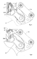
- the figure 3 shows the effect of lock lock 16.
- this step is performed by pulling on the shaft 17 by opposing the action of the compression spring 23.
- This traction can be performed by an actuator that can be controlled manually (by a specific lever that an operator uses to effect the axial displacement of the shaft 17) or electrically or hydraulically (for example by hydraulically feeding a chamber 38 defined by the end of the shaft 17 and the cap 25 ).
- the shaft 17 moves on its bearings 21 and 22 within the length of the groove 25 so that the lever 27 escapes the grip of the detection finger 32. This has the effect of rotating the shaft 17 and the locking latch 16 associated in the direction of its deactivation under the action of the torsion spring 24.
- the operating condition is that the springs 35, 37 always develop a greater torque on the shaft 17 than the spring 24. Inhibiting the action of 32 thus enables the spring 24 to act alone and to deactivate the lock 16.
- the figure 4 shows the connection set in this configuration. This figure clearly shows the lever 27 which is no longer pushed by the sensing pin 32. And the lock 16 has moved into the deactivated position under the action of the spring 24 alone.
- the blocking module 1 is then armed for a new connection.
- connection device 2 disposed on a tool schematically comprises two axes and a presence detection stop 109.
- the quick coupler coupler 4 comprises one or two hooks and a pivotable latch 114.
- the quick coupler 4 is furthermore provided with a locking module 1 which comprises a locking latch 116 pivotally mounted on the quick coupler coupler 4.
- the locking latch 116 is provided with a protrusion by which it is connected by a spring 124 to a fixed point of the quick coupler coupler 4.
- the blocking module 1 has, in addition, a sensing pin 132 of tool presence which is engaged in a bearing.
- This sensing pin 132 is slidable and is connected to the locking latch 116 by a spring 137, so that the movement of the sensing pin 132 towards its retracted position causes the action of the spring 124 to rotate, the rotation of the locking latch 116 to its activated position.
- the figure 8 represents more precisely the connection kinematics between the locking lever 116 and the detection finger 132.
- the compression spring 137 thus bears on the locking latch 116 knowing that it incorporates a pull tab 127 and a housing 116a which allows the compression spring 137 to bear against the pull tab 127.
- the zipper 127 has an evolutionary section as it appears on the figure 8 materialized; the pull tab 127 has indeed a wide section 127a which is connected to a thin section 127b by a ramp 127 c.
- the pull tab 127 is biased by a traction spring 123 which holds it in a so-called engaged position in which the wide portion 127a bears against the spring 137 (illustrated by the figure 8 ).
- the pull tab 127 is, in addition, connected to an actuator (manual or hydraulic) which can slide it inside the locking latch 116 from the engaged position in which the wide section 127a is opposite the spring 137 to a position said disengaged wherein the thinned section portion 127b is in contact with the spring 137, which is now released.
- an actuator manual or hydraulic
- This position is said to be disengaged (cf. Figure 10 ) because the force of the spring 137 has become weaker by the variation in section between the portions 127a and 127b, causes the latch 132 a lower torque than that induced by the spring 124. The latch 116 then switches to its deactivated position .
- the rotation of the locking latch 116 is limited in its activated position, by a stop 118 for the recovery of the locking forces. In its deactivated position, the bearing 143 in which the detection finger 132 slides limits its rotation.
- the locking latch 116 bears against the bearing 143 and is held in this position by the spring 124. In this position of the locking latch 116, the main latch 14 can freely rotate.
- the figure 7 shows the quick coupler coupler 4 in the approach phase. It can be seen that the main latch 14 is fixed on the axis 107 of the connection device 2. Simultaneously, the detection finger 132 comes into contact with the detection stop.
- the sensing pin 132 then rotates the lock 116 which is placed next to the main latch 14 thus preventing the rotation of the latter as it appears in FIG. figure 9 .
- the spring 124 is then subjected to a compression action by the effect of the sensing finger 132.
- the figure 10 shows the connection device 2 coupled to the quick coupler 4 with its associated blocking module 1 which authorizes now the release of the main lock 114.
- the action of the detection lock 132 is neutralized by the action on the pull tab 127, because although in the retracted position by the presence of the tool, the detection finger is temporarily without effect on the rotation of the locking latch 116, still subject to the action of the spring 124 which places it in its deactivated position.
- the quick coupler 4 can move away from the tool 2.
- the detection finger 132 loses contact with the detection stop 109, the spring 123 resets the pull tab 127 to its engaged position; the locking module is ready to ensure a new coupling as described in figure 7 .
- FIGS 12 to 14 schematically represent another embodiment of the blocking module according to the invention applied to a quick coupler coupler whose main lock is driven by a translation movement unlike previous embodiments in which the main lock is animated by a rotational movement.
- locking the quick coupler coupler on the connection device connected to a tool is shown schematically by a wedge-shaped hook 214 which engages in a complementary locking element 207.
- the locking module comprises a detecting finger 232 which is kinematically connected to a locking bolt 216.
- the connection is made by a spring 237 which transmits the movement of the detecting finger 232 to the locking bolt 216.
- the main bolt 214 has a cavity in which the locking latch 216 engages when the main latch 214 is in the locked position.
- a compression spring 224 pushes the locking latch 216 toward its disengaged position.
- a pull 227 linked in translation to the finger 232 is interposed between the spring 226 and the lock 216.
- the pull tab 227 has an evolutionary section as it appears on the figure 11 materialized by a wide section 227a and a thin section 227b, connected by a ramp 227c.
- the pull tab 227 is urged by a tension spring 223 which holds it in a so-called engaged position (illustrated by the figure 12 ) because the spring 237 in contact with the section 227a, is constrained and urges the lock 216 more than the spring 224, said latch moving to its activated or blocking position.
- the pull tab 227 is, in addition, connected to an actuator (manual or hydraulic) which can slide it inside the sensing pin 232, from the engaged position to a so-called disengaged position in which the thinned section portion 227b is in contact with the spring 237 which allows the relaxation.
- This position is said disengaged because the force applied by the spring 224 to the lock 216 is greater than the force developed by the spring 237 on the same lock 216, the position 227b of zipper 227 having relaxed the spring 237.
- the lock lock 216 then switches to its deactivated position (see figure 14 ).
- a stop 218 guards the locking latch 216 and resumes the unlocking forces induced by the main latch 214.
- the quick coupler coupler on which the blocking module is mounted approaches the tool 2 (cf. figure 12 ).
- the sensing pin 232 comes into contact with the sensing stop 209.
- the sensing pin 232 then moves into its retracted position which moves the locking lock 216 towards its activation position in which it locks in locked position the main lock 214 .
- the figure 13 illustrates this state of the blocking module.
- FIGS. 15 to 17 show an embodiment of a blocking module according to the invention, the overall operation and the chain of connection between a sensing pin 332 and a locking lock 316 are an electro-hydraulic circuit associated with an external control 350.
- the locking latch 316 is biased towards its locking position by a spring 324 integrated in a hydraulic cylinder 340 which can move it to its unlocked position.
- the sensing pin 332 is biased by a spring 337 towards its deployed position.
- a valve 338 is connected to the sensing finger; this feeds the actuator 340 and thus the latch 316 to its deactivated position, when the detection finger 332 is in its deployed position and towards its activated position, in its retracted position.
- valve 338 When the detection finger 332 comes into contact with a detection stop 309, the valve 338 reverses the hydraulic flow supplying the jack 340; this ensures the movement of the locking latch 316 towards its activated position.
- This state of the blocking module is represented at figure 16 . It may be noted that a stop 318 ensures recovery of the forces transmitted from the main latch 314 to the locking latch 316.
- a manual or electric actuator allows its control.
- the sequencing of the controls of the cylinder 340 and the valves 341, the locking cylinder 315 can be done by a logic control entity 350 driven by the operator of the machine.
- the figure 18 shows a further embodiment of the invention in which the lock is hydraulically made of the locking cylinder 315 is locked by a valve 338.
- the blocking of the oil in the rear chamber of the locking cylinder 315 ensures the maintenance contact locking surfaces 307 and 314.
- the movement of the cylinder 315 is authorized by the inhibiting means 341 which are themselves controlled by a control box.
- the invention proposes at least five embodiments of blocking modules.
- the blocking module according to the invention can therefore adapt to different types of locking assemblies to ensure blocking.
- the blocking module according to the invention can be integrated in a quick coupler coupler or can be retrofitted onto an existing quick coupler coupler to make an upgrade.
Landscapes
- Engineering & Computer Science (AREA)
- Mechanical Engineering (AREA)
- Mining & Mineral Resources (AREA)
- Civil Engineering (AREA)
- General Engineering & Computer Science (AREA)
- Structural Engineering (AREA)
- Quick-Acting Or Multi-Walled Pipe Joints (AREA)
Applications Claiming Priority (1)
| Application Number | Priority Date | Filing Date | Title |
|---|---|---|---|
| FR0952571A FR2944534B1 (fr) | 2009-04-20 | 2009-04-20 | Module de blocage pour un ensemble d'attache rapide d'un outil sur un engin de travaux publics. |
Publications (1)
| Publication Number | Publication Date |
|---|---|
| EP2243883A2 true EP2243883A2 (de) | 2010-10-27 |
Family
ID=41259707
Family Applications (1)
| Application Number | Title | Priority Date | Filing Date |
|---|---|---|---|
| EP20100160492 Withdrawn EP2243883A2 (de) | 2009-04-20 | 2010-04-20 | Verriegelungsmodul für Schnellkuppler an einer Arbeitsmaschine |
Country Status (2)
| Country | Link |
|---|---|
| EP (1) | EP2243883A2 (de) |
| FR (1) | FR2944534B1 (de) |
Cited By (7)
| Publication number | Priority date | Publication date | Assignee | Title |
|---|---|---|---|---|
| EP2860318A1 (de) * | 2013-10-14 | 2015-04-15 | Ateliers de Constructions du Beaujolais | Gesichertes Verbindungssystem zwischen einem Werkzeug und dem Arm einer Baumaschine |
| US10670479B2 (en) | 2018-02-27 | 2020-06-02 | Methode Electronics, Inc. | Towing systems and methods using magnetic field sensing |
| US10696109B2 (en) | 2017-03-22 | 2020-06-30 | Methode Electronics Malta Ltd. | Magnetolastic based sensor assembly |
| US11084342B2 (en) | 2018-02-27 | 2021-08-10 | Methode Electronics, Inc. | Towing systems and methods using magnetic field sensing |
| US11135882B2 (en) | 2018-02-27 | 2021-10-05 | Methode Electronics, Inc. | Towing systems and methods using magnetic field sensing |
| US11221262B2 (en) | 2018-02-27 | 2022-01-11 | Methode Electronics, Inc. | Towing systems and methods using magnetic field sensing |
| US11491832B2 (en) | 2018-02-27 | 2022-11-08 | Methode Electronics, Inc. | Towing systems and methods using magnetic field sensing |
Families Citing this family (1)
| Publication number | Priority date | Publication date | Assignee | Title |
|---|---|---|---|---|
| FR3019197A1 (fr) * | 2014-03-26 | 2015-10-02 | Morin | Systeme d’engagement d’un ensemble d’attache rapide |
Citations (1)
| Publication number | Priority date | Publication date | Assignee | Title |
|---|---|---|---|---|
| EP0438931A1 (de) | 1990-01-26 | 1991-07-31 | Societe En Nom Collectif Morin Freres | Vorrichtung zum Verbinden einer Schaufel, oder dergleichen, am Auslegerende eines Laders |
Family Cites Families (6)
| Publication number | Priority date | Publication date | Assignee | Title |
|---|---|---|---|---|
| FR2854415B1 (fr) * | 2003-04-30 | 2005-07-08 | Const Du Beaujolais Atel | Dispositif securise de verrouillage hydraulique d'attaches rapides et de connexions hydrauliques associees, entre le coupleur d'un bras porteur d'un engin et un outil |
| WO2007068043A1 (en) * | 2005-12-12 | 2007-06-21 | Positti, Nicole, Elizabeth | Safety device for hydraulic hitch assembly |
| FR2900168B1 (fr) * | 2006-04-21 | 2010-04-23 | Morin | Coupleur pour engin de travaux a deverrouillage mixte |
| ITBO20060631A1 (it) * | 2006-09-12 | 2008-03-13 | Cangini Benne Srl | Dispositivo per connettere un utensile ad un mezzo di azionamento. |
| FR2914932B1 (fr) * | 2007-04-10 | 2011-10-28 | Vente Et Entretien De Materiel | Dispositif de montage rapide d'un outil pivotant sur le bras d'une machine |
| CA2590464A1 (en) * | 2007-05-30 | 2008-11-30 | Brandt Industries Ltd. | Quick coupling mechanism for tool attachment |
-
2009
- 2009-04-20 FR FR0952571A patent/FR2944534B1/fr active Active
-
2010
- 2010-04-20 EP EP20100160492 patent/EP2243883A2/de not_active Withdrawn
Patent Citations (1)
| Publication number | Priority date | Publication date | Assignee | Title |
|---|---|---|---|---|
| EP0438931A1 (de) | 1990-01-26 | 1991-07-31 | Societe En Nom Collectif Morin Freres | Vorrichtung zum Verbinden einer Schaufel, oder dergleichen, am Auslegerende eines Laders |
Cited By (9)
| Publication number | Priority date | Publication date | Assignee | Title |
|---|---|---|---|---|
| EP2860318A1 (de) * | 2013-10-14 | 2015-04-15 | Ateliers de Constructions du Beaujolais | Gesichertes Verbindungssystem zwischen einem Werkzeug und dem Arm einer Baumaschine |
| FR3011859A1 (fr) * | 2013-10-14 | 2015-04-17 | Const Du Beaujolais Atel | Systeme de liaison securisee entre un outil et un bras d’un engin de travaux publics |
| US10696109B2 (en) | 2017-03-22 | 2020-06-30 | Methode Electronics Malta Ltd. | Magnetolastic based sensor assembly |
| US10940726B2 (en) | 2017-03-22 | 2021-03-09 | Methode Electronics Malta Ltd. | Magnetoelastic based sensor assembly |
| US10670479B2 (en) | 2018-02-27 | 2020-06-02 | Methode Electronics, Inc. | Towing systems and methods using magnetic field sensing |
| US11084342B2 (en) | 2018-02-27 | 2021-08-10 | Methode Electronics, Inc. | Towing systems and methods using magnetic field sensing |
| US11135882B2 (en) | 2018-02-27 | 2021-10-05 | Methode Electronics, Inc. | Towing systems and methods using magnetic field sensing |
| US11221262B2 (en) | 2018-02-27 | 2022-01-11 | Methode Electronics, Inc. | Towing systems and methods using magnetic field sensing |
| US11491832B2 (en) | 2018-02-27 | 2022-11-08 | Methode Electronics, Inc. | Towing systems and methods using magnetic field sensing |
Also Published As
| Publication number | Publication date |
|---|---|
| FR2944534A1 (fr) | 2010-10-22 |
| FR2944534B1 (fr) | 2016-09-23 |
Similar Documents
| Publication | Publication Date | Title |
|---|---|---|
| FR2944534A1 (fr) | Module de blocage pour un ensemble d'attache rapide d'un outil sur un engin de travaux publics. | |
| EP0534833B1 (de) | Verriegelungsvorrichtung mit Hakenriegel | |
| EP2748395B1 (de) | Verriegelungsvorrichtung mit mechanischer erkennung von schliessen und öffnen | |
| EP2691587B1 (de) | Sperrvorrichtung mit mechanischer detektion der verschliessung und öffnung | |
| FR2765916A1 (fr) | Inverseur de poussee a resistance amelioree aux impacts | |
| EP2930104B1 (de) | Verfahren zur bedienung der ladegutklappen eines luftfahrzeugs, und dazu verwendetes stellglied | |
| FR2935832A1 (fr) | Dispositif de prehension d'elements combustibles, pince et systeme de manutention associes | |
| FR2823259A1 (fr) | Systeme de verrouillage synchronise des portes d'un inverseur de poussee | |
| EP2300319B1 (de) | Zylindervorrichtung für flugzeugfahrwerk | |
| FR3063527A1 (fr) | Verin a verrouillage integre | |
| EP3877252B1 (de) | Notöffnungsvorrichtung für eine flugzeugtür mit drehfreigabe | |
| EP3222521B1 (de) | Verriegelbares deblockiersystem eines stellglieds am rad des fahrwerks eines luftfahrzeugs | |
| EP2013421B1 (de) | Baumaschine mit mischentriegelungsverbinder | |
| FR3022886A1 (fr) | Dispositif de deverrouillage d'un atterrisseur dans une position deployee et atterrisseur equipe d'un tel dispositif | |
| WO2020104908A2 (fr) | Conteneur équipé d'un système de verrouillage de conteneur | |
| EP1921235A1 (de) | Blockierriegel eines schwenkbaren Flügels | |
| FR2724957A1 (fr) | Coupleur a verrouillage autobloquant pour l'accouplement d'outils sur engin de chantier | |
| EP3924581B1 (de) | Vorrichtung zur unterstützung der bewegung eines öffnungselements eines kraftfahrzeugs | |
| EP0648994B1 (de) | Sperrvorrichtung für Ofentür | |
| EP4476136B1 (de) | Verfahren zur diagnose eines verschlechterungszustands eines türschlosses | |
| EP4476454A1 (de) | Verzögerungsventil und versorgungsschaltung eines zylinders mit einem solchen ventil | |
| EP3611389A1 (de) | Lineares stellglied mit verriegelung und verriegelungsanzeige | |
| EP0823370B1 (de) | Antriebsvorrichtung für einen Verriegelungszylinder eines Fahrwerkslenkers eines Fahrzeuges | |
| EP1036960B1 (de) | Vorrichtung in einem Schaltgetriebe für Kraftfahrzeuge zum Einbau und Zerlegen eines Kabels, welches einen Schalthebel mit einer Sicherheitssperre verbindet | |
| FR3000012A1 (fr) | Mecanisme de verrouillage de caisse de vehicule, agencement comprenant le mecanisme |
Legal Events
| Date | Code | Title | Description |
|---|---|---|---|
| PUAI | Public reference made under article 153(3) epc to a published international application that has entered the european phase |
Free format text: ORIGINAL CODE: 0009012 |
|
| AK | Designated contracting states |
Kind code of ref document: A2 Designated state(s): AT BE BG CH CY CZ DE DK EE ES FI FR GB GR HR HU IE IS IT LI LT LU LV MC MK MT NL NO PL PT RO SE SI SK SM TR |
|
| AX | Request for extension of the european patent |
Extension state: AL BA ME RS |
|
| STAA | Information on the status of an ep patent application or granted ep patent |
Free format text: STATUS: THE APPLICATION IS DEEMED TO BE WITHDRAWN |
|
| 18D | Application deemed to be withdrawn |
Effective date: 20161101 |