EP2243887A2 - Elément de ferrure - Google Patents
Elément de ferrure Download PDFInfo
- Publication number
- EP2243887A2 EP2243887A2 EP10160298A EP10160298A EP2243887A2 EP 2243887 A2 EP2243887 A2 EP 2243887A2 EP 10160298 A EP10160298 A EP 10160298A EP 10160298 A EP10160298 A EP 10160298A EP 2243887 A2 EP2243887 A2 EP 2243887A2
- Authority
- EP
- European Patent Office
- Prior art keywords
- fitting element
- fitting
- blocking
- element according
- screw head
- Prior art date
- Legal status (The legal status is an assumption and is not a legal conclusion. Google has not performed a legal analysis and makes no representation as to the accuracy of the status listed.)
- Granted
Links
Images


Classifications
-
- E—FIXED CONSTRUCTIONS
- E04—BUILDING
- E04B—GENERAL BUILDING CONSTRUCTIONS; WALLS, e.g. PARTITIONS; ROOFS; FLOORS; CEILINGS; INSULATION OR OTHER PROTECTION OF BUILDINGS
- E04B1/00—Constructions in general; Structures which are not restricted either to walls, e.g. partitions, or floors or ceilings or roofs
- E04B1/18—Structures comprising elongated load-supporting parts, e.g. columns, girders, skeletons
- E04B1/26—Structures comprising elongated load-supporting parts, e.g. columns, girders, skeletons the supporting parts consisting of wood
- E04B1/2604—Connections specially adapted therefor
-
- F—MECHANICAL ENGINEERING; LIGHTING; HEATING; WEAPONS; BLASTING
- F16—ENGINEERING ELEMENTS AND UNITS; GENERAL MEASURES FOR PRODUCING AND MAINTAINING EFFECTIVE FUNCTIONING OF MACHINES OR INSTALLATIONS; THERMAL INSULATION IN GENERAL
- F16B—DEVICES FOR FASTENING OR SECURING CONSTRUCTIONAL ELEMENTS OR MACHINE PARTS TOGETHER, e.g. NAILS, BOLTS, CIRCLIPS, CLAMPS, CLIPS OR WEDGES; JOINTS OR JOINTING
- F16B43/00—Washers or equivalent devices; Other devices for supporting bolt-heads or nuts
- F16B43/02—Washers or equivalent devices; Other devices for supporting bolt-heads or nuts with special provisions for engaging surfaces which are not perpendicular to a bolt axis or do not surround the bolt
- F16B43/025—Washers or equivalent devices; Other devices for supporting bolt-heads or nuts with special provisions for engaging surfaces which are not perpendicular to a bolt axis or do not surround the bolt for surfaces not surrounding the bolt, e.g. hook adaptors for bolts
-
- E—FIXED CONSTRUCTIONS
- E04—BUILDING
- E04B—GENERAL BUILDING CONSTRUCTIONS; WALLS, e.g. PARTITIONS; ROOFS; FLOORS; CEILINGS; INSULATION OR OTHER PROTECTION OF BUILDINGS
- E04B1/00—Constructions in general; Structures which are not restricted either to walls, e.g. partitions, or floors or ceilings or roofs
- E04B1/18—Structures comprising elongated load-supporting parts, e.g. columns, girders, skeletons
- E04B1/26—Structures comprising elongated load-supporting parts, e.g. columns, girders, skeletons the supporting parts consisting of wood
- E04B1/2604—Connections specially adapted therefor
- E04B2001/2644—Brackets, gussets or joining plates
-
- E—FIXED CONSTRUCTIONS
- E04—BUILDING
- E04B—GENERAL BUILDING CONSTRUCTIONS; WALLS, e.g. PARTITIONS; ROOFS; FLOORS; CEILINGS; INSULATION OR OTHER PROTECTION OF BUILDINGS
- E04B1/00—Constructions in general; Structures which are not restricted either to walls, e.g. partitions, or floors or ceilings or roofs
- E04B1/18—Structures comprising elongated load-supporting parts, e.g. columns, girders, skeletons
- E04B1/26—Structures comprising elongated load-supporting parts, e.g. columns, girders, skeletons the supporting parts consisting of wood
- E04B1/2604—Connections specially adapted therefor
- E04B2001/2652—Details of nailing, screwing, or bolting
Definitions
- the invention relates to a fitting element that can be fastened with screws.
- Full thread screws are known both for connecting steel to wood and for connecting wood together.
- connection of wood to wood not only tensile forces, but also compressive forces can be transmitted, whereby this transfer does not take place via the screw head, but via the thread.
- the invention is based on the object to provide a way to transmit axial compressive forces of screws in the screws to wooden structures to be fastened metal parts.
- the invention proposes a fitting element with the features mentioned in claim 1 and a fastening arrangement using such a fitting element. Further developments of the invention are the subject of dependent claims.
- the fitting element is applied with its contact surface to the object with which it is to be connected.
- a screw is then embroidered and screwed into the object until the screw rests with the underside of its screw head on the support at the outer end of the through hole.
- the blocking agent is attached to the fitting element in such a way that it bears against the end face of the screw head and prevents a backward movement of the screw head and thus of the screw. In this way, pressure forces can be introduced via the screw in the fitting element. From the fitting element forces can then be removed, for example, from the two ends of the fitting element.
- the through hole extends obliquely relative to the contact surface.
- the contact surface, with which the fitting element rests against the surface of the wooden structure is likewise flat.
- the contact surface of the fitting element has a different shape.
- the outer surface, from which the through hole emanates may be formed in a further development of the invention as a flat surface.
- the axis of the through-hole runs perpendicular to the outer surface having the entrance of the through-hole.
- Fitting elements of this type are usually screwed by means of several screws, so that the fitting element usefully has more than one through hole. It may be provided that, in the case of a plurality of through bores, at least two through bores run at an angle different from zero relative to one another.
- the blocking element may be formed in a development example, such that it extends from the outer surface forth in the through hole until it rests against the end face of the screw head accommodated therein.
- the support for the underside of the screw head must be arranged so that there is a gap between the outer surface and the end face of the screw head.
- a separate blocking element may be present, which is designed as a plug and is screwed, for example with a thread in the outer end of the through hole.
- plug-like blocking elements are arranged on a common plate, which is attached in any other way to the fitting element, for example by screws or by plugging.
- a blocking element may be formed, is that it rests as a plate or other element on the outer surface in the region of the through hole, without exhibiting projections or plugs.
- the support for the underside of the screw head is designed such that the screw head extends with its end face flush with the outer surface of the fitting element.
- the blocking element is formed by a profiled strip which has a shape complementary to the shape of the fitting element.
- the blocking element can verbu n-the be either with the fitting element, or with the object to which the fitting element is attached, or with both.
- the blocking element is designed in the form of a profiled strip, it can in particular also be designed such that it bears against a plurality of surfaces of the fitting element.
- the fitting element has the cross-sectional shape of a trapezoid, wherein in particular all surfaces of the fitting element are flat. Then, the longer side of the trapezoid forms the abutment surface, and the two adjacent oblique surfaces form the outer surfaces from which the through holes originate. At the same time, this ensures that the helical longitudinal axes extend from both sides at a non-zero angle and obliquely with respect to the contact surface.
- fitting element may be formed, is that the shape of a rhombus has.
- the blocking element can for example be positively connected to the fitting element, or non-positively, for example by a screw.
- a positive connection between the blocking element and the fitting element can for example be done in such a way that this is pushed in the direction of the longitudinal axis of the fitting element, ie parallel to the surface of the article.
- the blocking element can also be placed perpendicular to the surface of the article on the fitting element.
- the screw in the fitting element can also be blocked by a second adjoining fitting element, if it is adapted in its shape to the first fitting element in such a way that it can fulfill the function of blocking.
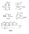
- the fitting element has the shape of a strip 1, which has a trapezoidal cross-section.
- the longer side of the trapezoid forms the contact surface 2.
- the inclined surfaces 3 form the outer surfaces, and the contact surface 2 opposite the front surface is 4. From the oblique outer surfaces 3 go in the illustrated embodiment, two through holes 5 through the fitting element. One of these through holes 5 is in FIG. 2 to see.
- the through hole 5 opens into the contact surface 2.
- the contact surface 2 opposite end of the through hole 5 is widened conical and thereby forms a support surface 7 for the underside of a screw head, which is designed as a countersunk head.
- the axis of the through hole 5 extends perpendicular to the outer surface 3, so that the end face of the screw head can be a flush inserted into the through hole 5 screw flush with the outer surface 3.
- each of two inclined bores 5 emanate from each inclined surface 3.
- This threaded hole 8 serves that in FIG. 3 screw shown blocking element 9 by means of a screw on the fitting element.
- the blocking element 9 is likewise designed as a strip and has on its one side a continuous channel 10, the profile of which is designed to be complementary to the profile of the fitting element.
- the one flank 11 is for abutment with the one outer side 3 of the fitting element formed, and the other edge 12 for engagement with the opposite outer side 3 of the fitting element.
- the bottom 13 connecting the two flanks 11, 12 is then located on the front surface 4 of the fitting element.
- a through hole 14 is formed, through which a screw can be screwed into the threaded hole 8 of the fitting element.
- the blocking element lies in the in FIG. 5 shown manner on the fitting element.
- the flanks 11, 12 are in contact with each other on the outer sides 3.
- a screw which is inserted through the through hole 5, held so that it can transmit not only tensile forces, but also compressive forces on the fitting element.
- the blocking element 9 is pushed or set up from a direction perpendicular to the object on which the fitting element is fastened with its contact surface 2.
- the attachment is done form-fitting with the help of a screw.
- a blocking element can look like and how it can be fixed.
- FIG. 7 shown, wherein the two parts, namely the fitting element 21 and the blocking element 29, are shown separately.
- the two outer surfaces 3 of the fitting element 21 are not quite up to the contact surface 2, and where there are the acute angle in a trapezoid, here is a notch 22 is provided, the walls of which run parallel or perpendicular to the contact surface 2.
- the blocking element again has the shape of a profile, and the The inner contour formed by two flanks 11, 12 and a bottom 13 corresponds to the outer contour of the fitting element 21.
- the two inwardly directed projections 23 present at the ends of the flanks 11, 12 correspond to the notch 22.
- This blocking element 29 can be located in the longitudinal direction of the fitting element 21 postpone on this, in which case the same situation as in the previous embodiment occurs when the blocking element 29 is pushed on.
- the flanks 11, 12 lie flat against the outer surfaces 3 of the fitting element 21.
- the fitting element 21 of FIG. 7 Incidentally, it is constructed in the same way as the fitting element of the previous embodiment, ie it likewise contains through-holes 5.
- FIG. 8 has the front surface 24 of the otherwise FIG. 1 same fitting element on a longitudinally continuous undercut T-shaped groove 25.
- the blocking element 39 has a projection 25 which extends in the longitudinal direction in a manner complementary to the groove 25 and, moreover, has the same structure as the blocking element 9 of FIG FIG. 3 , Also, this blocking element is pushed in the longitudinal direction of the fitting element 31 on this.
- the blocking element is fastened directly to the fitting element formed as a strip.
- FIG. 9 shows a blocking element 49, which has a similar shape as the blocking element 29 of FIG. 7 However, at the ends of the flanks 11, 12 outwardly directed flanges 26 are formed. These flanges 26 have holes 27.
- This blocking element 49 can be placed on a fitting element, in which case again the flanks 11, 12 rest against the outer surfaces 3. The attachment However, not or not only happens to the fitting element, but with the help of the holes 27 in the flanges 26 on the object to which the fitting element is screwed.
- FIG. 10 shows an embodiment, where the fitting element 51 is approximately the shape of the blocking element 9 of FIG. 3 has, while the blocking element, the cross-sectional shape of the fitting element 1 of FIG. 1 having.
- the attachment of the blocking member 59 to the fitting member 51 is done in the same manner as in the in FIGS. 1 to 6 illustrated embodiment.
- the screws or the through holes now run from the flank surfaces 53, which now take over the role of the outer surfaces 3. However, the through holes do not open out here in the contact surface 2.
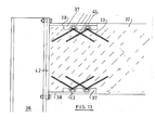
- FIG. 11 shows the application of several elements to a part 32 of a wooden construction.
- a fitting element 1 according to the illustration of Figures 1 and 2 , is bolted to the part 32 of the wood construction with a plurality of rows of screws represented by their dashed axes 33.
- a rhombic strip 34 is present both left and right, each having a through hole or a series of through holes, which emanate only from an outer surface 35. It can be arranged side by side in this way a plurality of fitting elements, with the exception of the two outermost diamond-shaped blocking elements every other blocking element also simultaneously assumes the role of a fitting element.
- the embodiment of the FIG. 12 a fitting element 61, in which the outer surface facing away from the contact surface 2 in cross-section a curvature has, for example, a semicircular or otherwise curved boundary line.
- the blocking element 69 has an inner shape, which is also formed as a curved line in cross section.
- the attachment of the blocking element 69 to the fitting element 61 can also be done any of the previously described manner, for example, that through an opening 14 of the blocking element 69 inserted through a screw and screwed into the threaded holes 8 of the fitting member 61.
- the cross-sectional shape for the fitting element may take any shapes, such as multi-corner, curved lines, combinations of polygons and curved lines, or the like.
- FIG. 13 the attachment of a wooden beam 32 to a steel beam 36 is shown.
- a recess 37 is milled.
- each two fitting elements are screwed according to the invention with the indicated screws 33.
- the blocking elements which are only indicated here, placed on the fitting elements and the wooden beams 32 inserted from the right between two tabs 38, which are welded parallel to each other with a steel plate 42.
- This steel plate 42 is bolted to the steel beam 36 with the screws and nuts shown.
- through holes 43 of the tabs 38 and through the holes 14 of the blocking elements screws into the holes 8 of the fitting elements screwed.
- the fitting elements are connected in the longitudinal direction of the wooden beam 32 with the tabs 38.
Landscapes
- Engineering & Computer Science (AREA)
- General Engineering & Computer Science (AREA)
- Architecture (AREA)
- Mechanical Engineering (AREA)
- Physics & Mathematics (AREA)
- Electromagnetism (AREA)
- Civil Engineering (AREA)
- Structural Engineering (AREA)
- Joining Of Building Structures In Genera (AREA)
Applications Claiming Priority (1)
| Application Number | Priority Date | Filing Date | Title |
|---|---|---|---|
| DE200910019086 DE102009019086A1 (de) | 2009-04-20 | 2009-04-20 | Beschlagelement |
Publications (3)
| Publication Number | Publication Date |
|---|---|
| EP2243887A2 true EP2243887A2 (fr) | 2010-10-27 |
| EP2243887A3 EP2243887A3 (fr) | 2011-04-27 |
| EP2243887B1 EP2243887B1 (fr) | 2016-10-12 |
Family
ID=42227726
Family Applications (1)
| Application Number | Title | Priority Date | Filing Date |
|---|---|---|---|
| EP10160298.5A Revoked EP2243887B1 (fr) | 2009-04-20 | 2010-04-19 | Elément de ferrure |
Country Status (2)
| Country | Link |
|---|---|
| EP (1) | EP2243887B1 (fr) |
| DE (1) | DE102009019086A1 (fr) |
Cited By (2)
| Publication number | Priority date | Publication date | Assignee | Title |
|---|---|---|---|---|
| EP2687645A1 (fr) | 2012-07-19 | 2014-01-22 | Rotho Blaas srl GmbH | Elément de liaison de composants, notamment de tableaux et de supports |
| US9809972B2 (en) | 2014-01-16 | 2017-11-07 | Rotho Blaas Srl Gmbh | Element for the connection of building components, particularly panels and beams |
Families Citing this family (1)
| Publication number | Priority date | Publication date | Assignee | Title |
|---|---|---|---|---|
| DE202013002224U1 (de) | 2013-03-07 | 2013-04-22 | Hubert Baumann | Vorrichtung zum Fixieren, Niederhalten von Befestigungselementen insbesondere für Schlagelemente |
Family Cites Families (7)
| Publication number | Priority date | Publication date | Assignee | Title |
|---|---|---|---|---|
| BE900495A (nl) * | 1984-09-04 | 1985-01-02 | Velda N V | Verbindingsstukken voor het aan elkaar verbinden van onderdelen. |
| EP0220337B1 (fr) * | 1985-11-01 | 1989-09-20 | Kabushiki Kaisha Murakoshi Seiko | Dispositif pour rayonnage |
| US5501559A (en) * | 1993-10-01 | 1996-03-26 | Sig Schweizerische Industrie-Gesellschaft | Screw connection for joining two components |
| AT409031B (de) * | 2000-06-27 | 2002-05-27 | Kaindl M | Vorrichtung zum verbinden zweier platten, insbesondere arbeitsplatten |
| DE20218592U1 (de) * | 2002-11-29 | 2003-03-13 | Pitzl, Ulrich, 84051 Essenbach | Verbindungseinrichtung |
| DE102006039248A1 (de) * | 2006-08-22 | 2008-02-28 | Erich Kahrs | Anordnung zum Verbinden von Profilen eines Tragwerks |
| DE202007014884U1 (de) | 2007-10-25 | 2008-01-03 | Bohrenkämper, Gustav | Verbindungsbeschlag |
-
2009
- 2009-04-20 DE DE200910019086 patent/DE102009019086A1/de not_active Withdrawn
-
2010
- 2010-04-19 EP EP10160298.5A patent/EP2243887B1/fr not_active Revoked
Non-Patent Citations (1)
| Title |
|---|
| None |
Cited By (2)
| Publication number | Priority date | Publication date | Assignee | Title |
|---|---|---|---|---|
| EP2687645A1 (fr) | 2012-07-19 | 2014-01-22 | Rotho Blaas srl GmbH | Elément de liaison de composants, notamment de tableaux et de supports |
| US9809972B2 (en) | 2014-01-16 | 2017-11-07 | Rotho Blaas Srl Gmbh | Element for the connection of building components, particularly panels and beams |
Also Published As
| Publication number | Publication date |
|---|---|
| EP2243887B1 (fr) | 2016-10-12 |
| EP2243887A3 (fr) | 2011-04-27 |
| DE102009019086A1 (de) | 2010-10-21 |
Similar Documents
| Publication | Publication Date | Title |
|---|---|---|
| EP2099971B1 (fr) | Ensemble de connecteur de joint de rail | |
| EP2885545B1 (fr) | Système de fixation | |
| DE102005044980B4 (de) | Stoßverbinder für Holz-/Aluminiumfassaden | |
| EP2243887B1 (fr) | Elément de ferrure | |
| DE102016103774B4 (de) | Verbindungsanordnung, Verbindungselement zur Verwendung in einer Verbindungsanordnung und Montageverfahren zur Herstellung einer Verbindungsanordnung | |
| EP0480957B1 (fr) | Agencement d'ancrage de barres | |
| DE29802951U1 (de) | Verbindungseinrichtung | |
| DE102009037820C5 (de) | Anordnung zur Verbindung von Holzbauteilen | |
| DE202011003315U1 (de) | Verbindungsvorrichtung | |
| EP3211146B1 (fr) | Systeme de liaison pour une construction en bois | |
| EP1635075B1 (fr) | Dispositif de connection | |
| EP2226440A2 (fr) | Elément de ferrure | |
| DE202007015154U1 (de) | System zur Befestigung eines Beschlagteils an einem Hohlprofil | |
| EP0846814A2 (fr) | Rail de montage | |
| DE20106841U1 (de) | Schiene für ein Fahrwerk einer Hängebahn | |
| DE102009008765B4 (de) | Beschlagelement | |
| DE202012008659U1 (de) | Lösbare Verbindung zwischen T-förmig aufeinandertreffenden Profilen | |
| EP4151865B1 (fr) | Système de connecteur | |
| EP3788210A1 (fr) | Système d'ancrage à force transversale | |
| DE102017121253B4 (de) | Verbindungsanordnung, Verbindungselement und Verfahren zur Herstellung einer Verbindungsanordnung | |
| EP3263788A1 (fr) | Liaison de deux poutres en bois | |
| EP3377711B1 (fr) | Rail profilé pour façade de bâtiment | |
| DE102004055556B4 (de) | Verbindungselement für Profile | |
| DE202005015416U1 (de) | Verbindungsbeschlag | |
| EP1746241A2 (fr) | Dispositf d'assemblage de panneaux |
Legal Events
| Date | Code | Title | Description |
|---|---|---|---|
| PUAI | Public reference made under article 153(3) epc to a published international application that has entered the european phase |
Free format text: ORIGINAL CODE: 0009012 |
|
| AK | Designated contracting states |
Kind code of ref document: A2 Designated state(s): AT BE BG CH CY CZ DE DK EE ES FI FR GB GR HR HU IE IS IT LI LT LU LV MC MK MT NL NO PL PT RO SE SI SK SM TR |
|
| AX | Request for extension of the european patent |
Extension state: AL BA ME RS |
|
| PUAL | Search report despatched |
Free format text: ORIGINAL CODE: 0009013 |
|
| AK | Designated contracting states |
Kind code of ref document: A3 Designated state(s): AT BE BG CH CY CZ DE DK EE ES FI FR GB GR HR HU IE IS IT LI LT LU LV MC MK MT NL NO PL PT RO SE SI SK SM TR |
|
| AX | Request for extension of the european patent |
Extension state: AL BA ME RS |
|
| RIC1 | Information provided on ipc code assigned before grant |
Ipc: F16B 41/00 20060101ALI20110324BHEP Ipc: E04B 1/26 20060101AFI20100615BHEP |
|
| 17P | Request for examination filed |
Effective date: 20111013 |
|
| 17Q | First examination report despatched |
Effective date: 20111227 |
|
| GRAP | Despatch of communication of intention to grant a patent |
Free format text: ORIGINAL CODE: EPIDOSNIGR1 |
|
| RIC1 | Information provided on ipc code assigned before grant |
Ipc: E04B 1/26 20060101AFI20160405BHEP Ipc: F16B 43/02 20060101ALI20160405BHEP |
|
| INTG | Intention to grant announced |
Effective date: 20160509 |
|
| GRAS | Grant fee paid |
Free format text: ORIGINAL CODE: EPIDOSNIGR3 |
|
| GRAA | (expected) grant |
Free format text: ORIGINAL CODE: 0009210 |
|
| AK | Designated contracting states |
Kind code of ref document: B1 Designated state(s): AT BE BG CH CY CZ DE DK EE ES FI FR GB GR HR HU IE IS IT LI LT LU LV MC MK MT NL NO PL PT RO SE SI SK SM TR |
|
| REG | Reference to a national code |
Ref country code: GB Ref legal event code: FG4D Free format text: NOT ENGLISH |
|
| REG | Reference to a national code |
Ref country code: CH Ref legal event code: EP |
|
| REG | Reference to a national code |
Ref country code: AT Ref legal event code: REF Ref document number: 836646 Country of ref document: AT Kind code of ref document: T Effective date: 20161015 |
|
| REG | Reference to a national code |
Ref country code: IE Ref legal event code: FG4D Free format text: LANGUAGE OF EP DOCUMENT: GERMAN |
|
| REG | Reference to a national code |
Ref country code: DE Ref legal event code: R096 Ref document number: 502010012539 Country of ref document: DE |
|
| REG | Reference to a national code |
Ref country code: CH Ref legal event code: NV Representative=s name: DR. LUSUARDI AG, CH |
|
| REG | Reference to a national code |
Ref country code: LT Ref legal event code: MG4D |
|
| REG | Reference to a national code |
Ref country code: NL Ref legal event code: MP Effective date: 20161012 |
|
| PG25 | Lapsed in a contracting state [announced via postgrant information from national office to epo] |
Ref country code: LV Free format text: LAPSE BECAUSE OF FAILURE TO SUBMIT A TRANSLATION OF THE DESCRIPTION OR TO PAY THE FEE WITHIN THE PRESCRIBED TIME-LIMIT Effective date: 20161012 |
|
| REG | Reference to a national code |
Ref country code: FR Ref legal event code: PLFP Year of fee payment: 8 |
|
| PG25 | Lapsed in a contracting state [announced via postgrant information from national office to epo] |
Ref country code: NO Free format text: LAPSE BECAUSE OF FAILURE TO SUBMIT A TRANSLATION OF THE DESCRIPTION OR TO PAY THE FEE WITHIN THE PRESCRIBED TIME-LIMIT Effective date: 20170112 Ref country code: GR Free format text: LAPSE BECAUSE OF FAILURE TO SUBMIT A TRANSLATION OF THE DESCRIPTION OR TO PAY THE FEE WITHIN THE PRESCRIBED TIME-LIMIT Effective date: 20170113 Ref country code: SE Free format text: LAPSE BECAUSE OF FAILURE TO SUBMIT A TRANSLATION OF THE DESCRIPTION OR TO PAY THE FEE WITHIN THE PRESCRIBED TIME-LIMIT Effective date: 20161012 Ref country code: LT Free format text: LAPSE BECAUSE OF FAILURE TO SUBMIT A TRANSLATION OF THE DESCRIPTION OR TO PAY THE FEE WITHIN THE PRESCRIBED TIME-LIMIT Effective date: 20161012 |
|
| PG25 | Lapsed in a contracting state [announced via postgrant information from national office to epo] |
Ref country code: PL Free format text: LAPSE BECAUSE OF FAILURE TO SUBMIT A TRANSLATION OF THE DESCRIPTION OR TO PAY THE FEE WITHIN THE PRESCRIBED TIME-LIMIT Effective date: 20161012 Ref country code: PT Free format text: LAPSE BECAUSE OF FAILURE TO SUBMIT A TRANSLATION OF THE DESCRIPTION OR TO PAY THE FEE WITHIN THE PRESCRIBED TIME-LIMIT Effective date: 20170213 Ref country code: HR Free format text: LAPSE BECAUSE OF FAILURE TO SUBMIT A TRANSLATION OF THE DESCRIPTION OR TO PAY THE FEE WITHIN THE PRESCRIBED TIME-LIMIT Effective date: 20161012 Ref country code: NL Free format text: LAPSE BECAUSE OF FAILURE TO SUBMIT A TRANSLATION OF THE DESCRIPTION OR TO PAY THE FEE WITHIN THE PRESCRIBED TIME-LIMIT Effective date: 20161012 Ref country code: IS Free format text: LAPSE BECAUSE OF FAILURE TO SUBMIT A TRANSLATION OF THE DESCRIPTION OR TO PAY THE FEE WITHIN THE PRESCRIBED TIME-LIMIT Effective date: 20170212 Ref country code: ES Free format text: LAPSE BECAUSE OF FAILURE TO SUBMIT A TRANSLATION OF THE DESCRIPTION OR TO PAY THE FEE WITHIN THE PRESCRIBED TIME-LIMIT Effective date: 20161012 Ref country code: FI Free format text: LAPSE BECAUSE OF FAILURE TO SUBMIT A TRANSLATION OF THE DESCRIPTION OR TO PAY THE FEE WITHIN THE PRESCRIBED TIME-LIMIT Effective date: 20161012 |
|
| REG | Reference to a national code |
Ref country code: DE Ref legal event code: R026 Ref document number: 502010012539 Country of ref document: DE |
|
| PLBI | Opposition filed |
Free format text: ORIGINAL CODE: 0009260 |
|
| PG25 | Lapsed in a contracting state [announced via postgrant information from national office to epo] |
Ref country code: SK Free format text: LAPSE BECAUSE OF FAILURE TO SUBMIT A TRANSLATION OF THE DESCRIPTION OR TO PAY THE FEE WITHIN THE PRESCRIBED TIME-LIMIT Effective date: 20161012 Ref country code: DK Free format text: LAPSE BECAUSE OF FAILURE TO SUBMIT A TRANSLATION OF THE DESCRIPTION OR TO PAY THE FEE WITHIN THE PRESCRIBED TIME-LIMIT Effective date: 20161012 Ref country code: RO Free format text: LAPSE BECAUSE OF FAILURE TO SUBMIT A TRANSLATION OF THE DESCRIPTION OR TO PAY THE FEE WITHIN THE PRESCRIBED TIME-LIMIT Effective date: 20161012 Ref country code: CZ Free format text: LAPSE BECAUSE OF FAILURE TO SUBMIT A TRANSLATION OF THE DESCRIPTION OR TO PAY THE FEE WITHIN THE PRESCRIBED TIME-LIMIT Effective date: 20161012 Ref country code: EE Free format text: LAPSE BECAUSE OF FAILURE TO SUBMIT A TRANSLATION OF THE DESCRIPTION OR TO PAY THE FEE WITHIN THE PRESCRIBED TIME-LIMIT Effective date: 20161012 |
|
| 26 | Opposition filed |
Opponent name: BOHRENKAEMPER GMBH Effective date: 20170710 |
|
| PG25 | Lapsed in a contracting state [announced via postgrant information from national office to epo] |
Ref country code: SM Free format text: LAPSE BECAUSE OF FAILURE TO SUBMIT A TRANSLATION OF THE DESCRIPTION OR TO PAY THE FEE WITHIN THE PRESCRIBED TIME-LIMIT Effective date: 20161012 Ref country code: IT Free format text: LAPSE BECAUSE OF FAILURE TO SUBMIT A TRANSLATION OF THE DESCRIPTION OR TO PAY THE FEE WITHIN THE PRESCRIBED TIME-LIMIT Effective date: 20161012 Ref country code: BG Free format text: LAPSE BECAUSE OF FAILURE TO SUBMIT A TRANSLATION OF THE DESCRIPTION OR TO PAY THE FEE WITHIN THE PRESCRIBED TIME-LIMIT Effective date: 20170112 |
|
| PLAX | Notice of opposition and request to file observation + time limit sent |
Free format text: ORIGINAL CODE: EPIDOSNOBS2 |
|
| PG25 | Lapsed in a contracting state [announced via postgrant information from national office to epo] |
Ref country code: SI Free format text: LAPSE BECAUSE OF FAILURE TO SUBMIT A TRANSLATION OF THE DESCRIPTION OR TO PAY THE FEE WITHIN THE PRESCRIBED TIME-LIMIT Effective date: 20161012 |
|
| GBPC | Gb: european patent ceased through non-payment of renewal fee |
Effective date: 20170419 |
|
| PLBB | Reply of patent proprietor to notice(s) of opposition received |
Free format text: ORIGINAL CODE: EPIDOSNOBS3 |
|
| REG | Reference to a national code |
Ref country code: IE Ref legal event code: MM4A |
|
| PG25 | Lapsed in a contracting state [announced via postgrant information from national office to epo] |
Ref country code: MC Free format text: LAPSE BECAUSE OF FAILURE TO SUBMIT A TRANSLATION OF THE DESCRIPTION OR TO PAY THE FEE WITHIN THE PRESCRIBED TIME-LIMIT Effective date: 20161012 |
|
| PG25 | Lapsed in a contracting state [announced via postgrant information from national office to epo] |
Ref country code: GB Free format text: LAPSE BECAUSE OF NON-PAYMENT OF DUE FEES Effective date: 20170419 Ref country code: LU Free format text: LAPSE BECAUSE OF NON-PAYMENT OF DUE FEES Effective date: 20170419 |
|
| REG | Reference to a national code |
Ref country code: BE Ref legal event code: MM Effective date: 20170430 |
|
| REG | Reference to a national code |
Ref country code: FR Ref legal event code: PLFP Year of fee payment: 9 |
|
| PG25 | Lapsed in a contracting state [announced via postgrant information from national office to epo] |
Ref country code: IE Free format text: LAPSE BECAUSE OF NON-PAYMENT OF DUE FEES Effective date: 20170419 |
|
| PG25 | Lapsed in a contracting state [announced via postgrant information from national office to epo] |
Ref country code: BE Free format text: LAPSE BECAUSE OF NON-PAYMENT OF DUE FEES Effective date: 20170430 |
|
| PGFP | Annual fee paid to national office [announced via postgrant information from national office to epo] |
Ref country code: CH Payment date: 20180419 Year of fee payment: 9 Ref country code: DE Payment date: 20180420 Year of fee payment: 9 |
|
| PGFP | Annual fee paid to national office [announced via postgrant information from national office to epo] |
Ref country code: AT Payment date: 20180419 Year of fee payment: 9 Ref country code: FR Payment date: 20180420 Year of fee payment: 9 |
|
| PG25 | Lapsed in a contracting state [announced via postgrant information from national office to epo] |
Ref country code: MT Free format text: LAPSE BECAUSE OF FAILURE TO SUBMIT A TRANSLATION OF THE DESCRIPTION OR TO PAY THE FEE WITHIN THE PRESCRIBED TIME-LIMIT Effective date: 20161012 |
|
| RDAF | Communication despatched that patent is revoked |
Free format text: ORIGINAL CODE: EPIDOSNREV1 |
|
| STAA | Information on the status of an ep patent application or granted ep patent |
Free format text: STATUS: THE PATENT HAS BEEN GRANTED |
|
| REG | Reference to a national code |
Ref country code: DE Ref legal event code: R064 Ref document number: 502010012539 Country of ref document: DE Ref country code: DE Ref legal event code: R103 Ref document number: 502010012539 Country of ref document: DE |
|
| RDAG | Patent revoked |
Free format text: ORIGINAL CODE: 0009271 |
|
| STAA | Information on the status of an ep patent application or granted ep patent |
Free format text: STATUS: PATENT REVOKED |
|
| REG | Reference to a national code |
Ref country code: CH Ref legal event code: PL |
|
| 27W | Patent revoked |
Effective date: 20190311 |
|
| REG | Reference to a national code |
Ref country code: AT Ref legal event code: MA03 Ref document number: 836646 Country of ref document: AT Kind code of ref document: T Effective date: 20190311 |
|
| PG25 | Lapsed in a contracting state [announced via postgrant information from national office to epo] |
Ref country code: MK Free format text: LAPSE BECAUSE OF FAILURE TO SUBMIT A TRANSLATION OF THE DESCRIPTION OR TO PAY THE FEE WITHIN THE PRESCRIBED TIME-LIMIT Effective date: 20161012 |
|
| PG25 | Lapsed in a contracting state [announced via postgrant information from national office to epo] |
Ref country code: CY Free format text: LAPSE BECAUSE OF FAILURE TO SUBMIT A TRANSLATION OF THE DESCRIPTION OR TO PAY THE FEE WITHIN THE PRESCRIBED TIME-LIMIT Effective date: 20161012 |
|
| PG25 | Lapsed in a contracting state [announced via postgrant information from national office to epo] |
Ref country code: TR Free format text: LAPSE BECAUSE OF FAILURE TO SUBMIT A TRANSLATION OF THE DESCRIPTION OR TO PAY THE FEE WITHIN THE PRESCRIBED TIME-LIMIT Effective date: 20161012 |