EP2243932A2 - Turbomachine axiale avec une tuyère de guidage comprenant un étage d'aubes de guidage variables - Google Patents
Turbomachine axiale avec une tuyère de guidage comprenant un étage d'aubes de guidage variables Download PDFInfo
- Publication number
- EP2243932A2 EP2243932A2 EP10152861A EP10152861A EP2243932A2 EP 2243932 A2 EP2243932 A2 EP 2243932A2 EP 10152861 A EP10152861 A EP 10152861A EP 10152861 A EP10152861 A EP 10152861A EP 2243932 A2 EP2243932 A2 EP 2243932A2
- Authority
- EP
- European Patent Office
- Prior art keywords
- hub
- guide vanes
- guide
- exhaust gas
- gas turbocharger
- Prior art date
- Legal status (The legal status is an assumption and is not a legal conclusion. Google has not performed a legal analysis and makes no representation as to the accuracy of the status listed.)
- Granted
Links
Images
Classifications
-
- F—MECHANICAL ENGINEERING; LIGHTING; HEATING; WEAPONS; BLASTING
- F01—MACHINES OR ENGINES IN GENERAL; ENGINE PLANTS IN GENERAL; STEAM ENGINES
- F01D—NON-POSITIVE DISPLACEMENT MACHINES OR ENGINES, e.g. STEAM TURBINES
- F01D9/00—Stators
- F01D9/02—Nozzles; Nozzle boxes; Stator blades; Guide conduits, e.g. individual nozzles
-
- F—MECHANICAL ENGINEERING; LIGHTING; HEATING; WEAPONS; BLASTING
- F01—MACHINES OR ENGINES IN GENERAL; ENGINE PLANTS IN GENERAL; STEAM ENGINES
- F01D—NON-POSITIVE DISPLACEMENT MACHINES OR ENGINES, e.g. STEAM TURBINES
- F01D17/00—Regulating or controlling by varying flow
- F01D17/10—Final actuators
- F01D17/12—Final actuators arranged in stator parts
- F01D17/14—Final actuators arranged in stator parts varying effective cross-sectional area of nozzles or guide conduits
- F01D17/16—Final actuators arranged in stator parts varying effective cross-sectional area of nozzles or guide conduits by means of nozzle vanes
- F01D17/162—Final actuators arranged in stator parts varying effective cross-sectional area of nozzles or guide conduits by means of nozzle vanes for axial flow, i.e. the vanes turning around axes which are essentially perpendicular to the rotor centre line
-
- F—MECHANICAL ENGINEERING; LIGHTING; HEATING; WEAPONS; BLASTING
- F05—INDEXING SCHEMES RELATING TO ENGINES OR PUMPS IN VARIOUS SUBCLASSES OF CLASSES F01-F04
- F05D—INDEXING SCHEME FOR ASPECTS RELATING TO NON-POSITIVE-DISPLACEMENT MACHINES OR ENGINES, GAS-TURBINES OR JET-PROPULSION PLANTS
- F05D2220/00—Application
- F05D2220/40—Application in turbochargers
Definitions
- the invention relates to an exhaust gas turbocharger turbine with a number of adjustable guide vanes comprehensive in the flow channel, which is bounded on the one hand by an inner hub and the other by an outer vane support, wherein the vanes are rotatably mounted on the one hand in radial bearing bores of the annular vane support and on the other hand with seal their head profile against the guide vane, and with their foot profile against the hub, so the guide vanes are mounted on one side.
- Adjustable, in particular turbine nozzles are known to be used in turbine and turbocharger construction to better adapt the turbine during operation to the respective operating state.
- the boost pressure and thus the supply of air for a given load point can be changed within certain limits.
- the pressure increase can be limited so that set at full load, the purge air pressure and thus the ignition pressure and fuel consumption of the engine normally designed.
- the efficiency of the turbine with an adjustable turbine nozzle in particular during operation away from the design point, be raised or lowered.
- adjustable turbine nozzles have a plurality of rotatable about an axis arranged vanes, which are articulated via levers and collars.
- adjustable turbine nozzles for axially and radially traversed turbines. While the radially flowed adjustable turbine nozzle can be relatively simple (see, for example DE 42 18 229 C1 ), the axially flowed through is much more expensive to realize, since in particular the hub and Zuströmgepurtur spherical, ie at least curved must be designed. This is necessary to produce a uniform radial gap at all blade positions toward the hub and inflator housing contours.
- a generic axial flow machine, in particular axial flow turbine shows the DE 42 13 709 A1 .
- the adjustable turbine nozzle offers the possibility of reducing the flow cross-section in the turbine at partial load of the engine and thereby raising the air pressure in front of the cylinder.
- the known axially flowed adjustable turbine nozzle comprises within the annular flow passage defining walls on the one hand, the inner hub and on the other hand, the hub ring-shaped outer stator blade carrier, which is mounted in the inlet housing of the turbine.
- vanes do not jam during "hot” operation, they usually need to be installed with adequate clearance.
- the resulting slit flows at the top and bottom of the vanes can interfere with the main flow in the duct.
- the invention has the object of developing an exhaust gas turbocharger such that the components of the diffuser are both smoothly actuated, and allow only small gap flows.
- both above-mentioned requirements should be combined in a new axial flow machine.
- the hub is designed at least in the sealing region of theticianprofiles the vanes with a resilient hub contour and the one-sided storage of the vanes in the vane support in the direction of the vanes is also designed compliant, the flow losses through gaps between the Leitschaufel- and the Zuströmgepatuse- or hub contours be reduced and also to avoid distortion of the components of the adjustable nozzle, caused by sealing elements and thermal expansion of the components.
- the inner ring is provided for Monday with a slot, so that a thermal expansion is compensated here as well.
- the slot is arranged so that it lies between two guide vanes and is not swept by the blade contour during an adjustment process, so that the losses caused by the slot can be minimized.
- the inner ring is flanged to the hub so that it is movable in the radial direction of the Zuströmgeophuses, ie in the direction of the vane axis, in the axial direction of the Zuströmgepatuse but only with little play is inserted into the hub contour. By this measure again mass flow losses are avoided.
- the inner contour of the annular guide carrier, the hub, as well as the head and foot profiles of the vanes are designed to improve the sealing effect according to spherical.
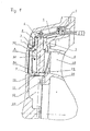
- FIG. 1 a partial longitudinal section through an exhaust gas turbocharger.
- An axial flow-through, annular channel 20 of an axial turbine is limited on the one hand by an inner hub 21 and on the other by an annular guide vane carrier 7 together with Zuströmgephaseuse 8.
- the vane support 7 is mounted in a manner not described in detail in the Zuströmgephase 8.
- the adjustable guide vanes 30 each comprise a stator blade 1, a blade journal 2 and a blade turntable 3.
- the blade journal 2 is rotatably mounted in a radial bearing bore of the annular guide blade carrier 7 and fixed in a known manner, for example by means of a screwed crown nut or the like on the guide vane carrier 7.
- an articulated lever 5 is rotationally fixed by means of a key on the extended pin 2 of the guide vane 30.
- the articulated lever 5 is contacted with the blade journal 2 and the guide blade carrier 7 with the interposition of a plate spring 4, so that the articulation lever 5 is supported against the guide blade carrier 7.
- the plate spring 4 exerts on the blade journal 2 a Biasing force, by which the base profile 31, ie the lower contour of the vane blade 1 is pressed against the outer surface of the hub 21, so the base profile 31 of the vane 30 is at the stop with the hub 21 and thus seals against the contour of the hub 21.
- the blade journal 2 in the bearing bore of the guide blade carrier 7 almost free of play, but still clamped against thermal expansion in the direction of the axis A of the vane 30 elastic and vibration damping.
- the blade turntable 3 seals the channel 20 against the bearing bore of the guide blade carrier 7.
- the articulated lever 5 is movable in a known manner via a collar 6 by means not shown actuating means.
- the housing contour of the hub 21 is designed at least partially spherical with the inclusion of a hollow or inner space 22.
- an inner ring 9 is fitted in the Nabekontur, which is supported in the prestressed state against the base profile 31 of the vane 30 and is secured by a flange 12 to the hub 21 so that it in the direction of the axis
- the guide vane 30 is movable, it has only slight play in the contour of the hub 21, that is to say in the axial direction of the channel 20.
- the inner ring 9 itself is provided with a slot 10 which is arranged so that it lies between two guide vanes and is not swept by the blade contour during the adjustment process. In order to prevent mass flow losses through the slot 10, it is covered by the hollow or inner space 22 of the hub 21 seen with a sealing plate 11.
Landscapes
- Engineering & Computer Science (AREA)
- Mechanical Engineering (AREA)
- General Engineering & Computer Science (AREA)
- Control Of Turbines (AREA)
- Turbine Rotor Nozzle Sealing (AREA)
- Supercharger (AREA)
- Structures Of Non-Positive Displacement Pumps (AREA)
Applications Claiming Priority (2)
| Application Number | Priority Date | Filing Date | Title |
|---|---|---|---|
| DE10016745A DE10016745B4 (de) | 2000-04-04 | 2000-04-04 | Axialströmungsmaschine mit einem eine Reihe von verstellbaren Leitschaufeln umfassenden Leitapparat |
| EP01108009A EP1143111B8 (fr) | 2000-04-04 | 2001-03-29 | Turbomachine axiale avec des aubes de guidage variables |
Related Parent Applications (2)
| Application Number | Title | Priority Date | Filing Date |
|---|---|---|---|
| EP01108009A Division EP1143111B8 (fr) | 2000-04-04 | 2001-03-29 | Turbomachine axiale avec des aubes de guidage variables |
| EP01108009.0 Division | 2001-03-29 |
Publications (3)
| Publication Number | Publication Date |
|---|---|
| EP2243932A2 true EP2243932A2 (fr) | 2010-10-27 |
| EP2243932A3 EP2243932A3 (fr) | 2011-01-26 |
| EP2243932B1 EP2243932B1 (fr) | 2019-03-13 |
Family
ID=7637566
Family Applications (2)
| Application Number | Title | Priority Date | Filing Date |
|---|---|---|---|
| EP01108009A Expired - Lifetime EP1143111B8 (fr) | 2000-04-04 | 2001-03-29 | Turbomachine axiale avec des aubes de guidage variables |
| EP10152861.0A Expired - Lifetime EP2243932B1 (fr) | 2000-04-04 | 2001-03-29 | Turbomachine axiale avec une tuyère de guidage comprenant un étage d'aubes de guidage variables |
Family Applications Before (1)
| Application Number | Title | Priority Date | Filing Date |
|---|---|---|---|
| EP01108009A Expired - Lifetime EP1143111B8 (fr) | 2000-04-04 | 2001-03-29 | Turbomachine axiale avec des aubes de guidage variables |
Country Status (6)
| Country | Link |
|---|---|
| US (1) | US6547521B2 (fr) |
| EP (2) | EP1143111B8 (fr) |
| JP (1) | JP2001289004A (fr) |
| KR (1) | KR100824894B1 (fr) |
| CN (1) | CN1278019C (fr) |
| DE (2) | DE10016745B4 (fr) |
Families Citing this family (15)
| Publication number | Priority date | Publication date | Assignee | Title |
|---|---|---|---|---|
| DE102005040574A1 (de) * | 2005-08-26 | 2007-03-15 | Rolls-Royce Deutschland Ltd & Co Kg | Spaltkontrollvorrichtung für eine Gasturbine |
| CH698928B1 (de) * | 2006-05-18 | 2009-12-15 | Man Diesel Se | Leitapparat für eine axial angeströmte Turbine eines Abgasturboladers. |
| DE102007021448B4 (de) * | 2006-05-18 | 2012-06-28 | Man Diesel & Turbo Se | Leitapparat für einen Abgasturbolader einer mit Schweröl betriebenen Hubkolben-Brennkraftmaschine |
| CN102159794B (zh) * | 2008-09-18 | 2015-04-15 | 西门子公司 | 用于可变导向叶片的方法、系统和装置 |
| US8668445B2 (en) * | 2010-10-15 | 2014-03-11 | General Electric Company | Variable turbine nozzle system |
| CN102606223B (zh) * | 2011-01-24 | 2014-12-17 | 中国石油化工集团公司 | 一种烟气轮机 |
| DE102011119879A1 (de) * | 2011-12-01 | 2013-06-06 | Ihi Charging Systems International Gmbh | Fluidenergiemaschine, insbesondere für einen Abgasturbolader eines Kraftwagens |
| DE102016110269A1 (de) | 2016-06-03 | 2017-12-07 | Man Diesel & Turbo Se | Axialturbine eines Turboladers und Turbolader |
| DE102016114253A1 (de) * | 2016-08-02 | 2018-02-08 | Man Diesel & Turbo Se | Axialturbine eines Turboladers und Turbolader |
| DE102018101527A1 (de) | 2018-01-24 | 2019-07-25 | Man Energy Solutions Se | Axialströmungsmaschine |
| CN112989720B (zh) * | 2021-03-04 | 2022-05-06 | 上海交通大学 | 轴流压气机悬臂静子叶片优化轮毂径向间隙实现方法 |
| US12416262B2 (en) | 2023-02-17 | 2025-09-16 | General Electric Company | Reverse flow gas turbine engine having electric machine |
| US12221894B2 (en) | 2023-03-20 | 2025-02-11 | General Electric Company Polska Sp. Z O.O. | Compressor with anti-ice inlet |
| EP4435235A1 (fr) * | 2023-03-20 | 2024-09-25 | General Electric Company Polska Sp. Z o.o | Compresseur et moteur turboprop |
| FR3163396A1 (fr) | 2024-06-12 | 2025-12-19 | Safran Aircraft Engines | Mecanisme de commande d’aubes de stator de turbomachine avec au moins un raidisseur |
Family Cites Families (17)
| Publication number | Priority date | Publication date | Assignee | Title |
|---|---|---|---|---|
| BE514728A (fr) * | 1951-10-10 | |||
| CH360074A (de) * | 1957-10-31 | 1962-02-15 | Maschf Augsburg Nuernberg Ag | Leitapparat mit im Betrieb verstellbaren Schaufeln, besonders für Gasturbinen |
| US3542484A (en) * | 1968-08-19 | 1970-11-24 | Gen Motors Corp | Variable vanes |
| FR2030895A5 (fr) * | 1969-05-23 | 1970-11-13 | Motoren Turbinen Union | |
| US3999883A (en) * | 1975-07-02 | 1976-12-28 | General Motors Corporation | Variable turbomachine stator |
| DE2740192C2 (de) | 1977-09-07 | 1981-11-12 | Mtu Motoren- Und Turbinen-Union Muenchen Gmbh, 8000 Muenchen | Spaltdichtung für eine um ihre Längsachse verstellbare, axial umströmte Leitschaufel einer Strömungsmaschine |
| DE2931766C2 (de) * | 1979-08-04 | 1982-08-05 | MTU Motoren- und Turbinen-Union München GmbH, 8000 München | Dichtungseinrichtung für die freien Schaufelenden eines Verstell-Leitapparates einer Gasturbine |
| GB2210935B (en) * | 1987-10-10 | 1992-05-27 | Rolls Royce Plc | Variable stator vane assembly |
| GB8914577D0 (en) * | 1989-06-24 | 1989-08-16 | Ici Plc | Catalysts |
| DE4017861A1 (de) * | 1990-06-02 | 1991-12-05 | Mtu Muenchen Gmbh | Leitkranz fuer eine gasturbine |
| DE4213716A1 (de) * | 1992-04-25 | 1993-10-28 | Asea Brown Boveri | Axialdurchströmte Turbine |
| DE4213709A1 (de) | 1992-04-25 | 1993-10-28 | Asea Brown Boveri | Axialdurchströmte Turbine |
| DE4218229C1 (en) | 1992-06-03 | 1993-03-04 | Man B & W Diesel Ag, 8900 Augsburg, De | Turbocharger with radial flow through impeller - has blade retaining recesses, into which blades are insertable after axial shift of adjuster |
| DE4237031C1 (de) | 1992-11-03 | 1994-02-10 | Mtu Muenchen Gmbh | Verstellbare Leitschaufel |
| US5672047A (en) * | 1995-04-12 | 1997-09-30 | Dresser-Rand Company | Adjustable stator vanes for turbomachinery |
| JPH09203371A (ja) * | 1996-01-26 | 1997-08-05 | Hitachi Ltd | 土砂摩耗対応水力機器 |
| FR2775731B1 (fr) * | 1998-03-05 | 2000-04-07 | Snecma | Etage circulaire d'aubes aux extremites interieures unies par un anneau de liaison |
-
2000
- 2000-04-04 DE DE10016745A patent/DE10016745B4/de not_active Expired - Fee Related
-
2001
- 2001-03-29 DE DE50115388T patent/DE50115388D1/de not_active Expired - Lifetime
- 2001-03-29 EP EP01108009A patent/EP1143111B8/fr not_active Expired - Lifetime
- 2001-03-29 EP EP10152861.0A patent/EP2243932B1/fr not_active Expired - Lifetime
- 2001-03-30 JP JP2001100202A patent/JP2001289004A/ja active Pending
- 2001-04-03 KR KR1020010017559A patent/KR100824894B1/ko not_active Expired - Lifetime
- 2001-04-04 US US09/825,955 patent/US6547521B2/en not_active Expired - Lifetime
- 2001-04-04 CN CNB011124733A patent/CN1278019C/zh not_active Expired - Lifetime
Also Published As
| Publication number | Publication date |
|---|---|
| EP2243932B1 (fr) | 2019-03-13 |
| EP1143111A2 (fr) | 2001-10-10 |
| CN1316582A (zh) | 2001-10-10 |
| EP1143111A3 (fr) | 2003-05-07 |
| JP2001289004A (ja) | 2001-10-19 |
| DE50115388D1 (de) | 2010-04-29 |
| DE10016745B4 (de) | 2005-05-19 |
| KR100824894B1 (ko) | 2008-04-23 |
| EP1143111B8 (fr) | 2010-05-19 |
| CN1278019C (zh) | 2006-10-04 |
| EP1143111B1 (fr) | 2010-03-17 |
| US20010026758A1 (en) | 2001-10-04 |
| KR20010095249A (ko) | 2001-11-03 |
| DE10016745A1 (de) | 2001-10-18 |
| EP2243932A3 (fr) | 2011-01-26 |
| US6547521B2 (en) | 2003-04-15 |
Similar Documents
| Publication | Publication Date | Title |
|---|---|---|
| EP2243932B1 (fr) | Turbomachine axiale avec une tuyère de guidage comprenant un étage d'aubes de guidage variables | |
| DE3028137C2 (fr) | ||
| DE2626406C2 (de) | Gasturbinentriebwerk mit variablem Zyklus | |
| DE69719579T2 (de) | Rotorschaufelspitzenabdichtung einer Turbomaschine | |
| DE2840336C2 (de) | Dichtung für eine verstellbare Turbinenlaufschaufel | |
| DE3941174C2 (de) | Spitzenspalt-Einstellvorrichtung für die Turbinenrotorschaufeln eines Gasturbinentriebwerks | |
| DE102011054468B4 (de) | Variables Turbinenleitapparatsystem | |
| EP1834066B1 (fr) | Aube de turbine pour turbine a gaz, utilisation d'une aube de turbine et procede de refroidissement d'une aube de turbine | |
| DE4309636C2 (de) | Radialdurchströmte Abgasturboladerturbine | |
| EP0568909B1 (fr) | Obturateur à disque rotatif pour turbine à gaz | |
| DE102017202137B4 (de) | Klappeneinrichtung zum Öffnen und Schließen eines Wastegatekanals in einem Turbinengehäuse eines Turboladers sowie Turbolader | |
| DE2454054C2 (de) | Einwelliges Grundtriebwerk für Zweistrom-Gasturbinentriebwerke | |
| DE3206209A1 (de) | "luftsteuervorrichtung fuer ein gasturbinentriebwerk | |
| DE102018221812B4 (de) | Abgasturbine mit einer Abgasleiteinrichtung für einen Abgasturbolader und Abgasturbolader | |
| DE3627306A1 (de) | Einrichtung zur belueftung von rotorbauteilen fuer verdichter von gasturbinentriebwerken | |
| EP0806548A1 (fr) | Turbine d'un turbocompresseur à gaz d'échappement | |
| EP1706597B1 (fr) | Turbine a gaz avec rotor axialement deplacable | |
| EP2054587B1 (fr) | Boîtier de turbine | |
| CH698928B1 (de) | Leitapparat für eine axial angeströmte Turbine eines Abgasturboladers. | |
| EP2785982A1 (fr) | Machine à énergie hydraulique ou pneumatique, en particulier pour un turbocompresseur, doté d'un élément de guidage rotatif disposé en biais | |
| EP2411631B1 (fr) | Plaque d'étanchéité et système d'aube tournante | |
| DE19839592A1 (de) | Strömungsmaschine mit gekühlter Rotorwelle | |
| EP0567784A1 (fr) | Turbine à écoulement axial | |
| DE3844189A1 (de) | Verstellbarer radialdiffusor fuer einen verdichter | |
| DE102021134071A1 (de) | Radialturbine mit vtg-leitgitter |
Legal Events
| Date | Code | Title | Description |
|---|---|---|---|
| PUAI | Public reference made under article 153(3) epc to a published international application that has entered the european phase |
Free format text: ORIGINAL CODE: 0009012 |
|
| AC | Divisional application: reference to earlier application |
Ref document number: 1143111 Country of ref document: EP Kind code of ref document: P |
|
| AK | Designated contracting states |
Kind code of ref document: A2 Designated state(s): CH DE FR GB IT LI |
|
| PUAL | Search report despatched |
Free format text: ORIGINAL CODE: 0009013 |
|
| AK | Designated contracting states |
Kind code of ref document: A3 Designated state(s): CH DE FR GB IT LI |
|
| RIC1 | Information provided on ipc code assigned before grant |
Ipc: F02C 6/12 20060101ALI20101220BHEP Ipc: F01D 17/16 20060101AFI20100921BHEP Ipc: F01D 11/00 20060101ALI20101220BHEP |
|
| 17P | Request for examination filed |
Effective date: 20110719 |
|
| 17Q | First examination report despatched |
Effective date: 20110913 |
|
| RAP1 | Party data changed (applicant data changed or rights of an application transferred) |
Owner name: MAN DIESEL & TURBO SE |
|
| GRAP | Despatch of communication of intention to grant a patent |
Free format text: ORIGINAL CODE: EPIDOSNIGR1 |
|
| INTG | Intention to grant announced |
Effective date: 20181112 |
|
| RAP1 | Party data changed (applicant data changed or rights of an application transferred) |
Owner name: MAN ENERGY SOLUTIONS SE |
|
| GRAS | Grant fee paid |
Free format text: ORIGINAL CODE: EPIDOSNIGR3 |
|
| GRAA | (expected) grant |
Free format text: ORIGINAL CODE: 0009210 |
|
| AC | Divisional application: reference to earlier application |
Ref document number: 1143111 Country of ref document: EP Kind code of ref document: P |
|
| AK | Designated contracting states |
Kind code of ref document: B1 Designated state(s): CH DE FR GB IT LI |
|
| REG | Reference to a national code |
Ref country code: GB Ref legal event code: FG4D Free format text: NOT ENGLISH |
|
| REG | Reference to a national code |
Ref country code: CH Ref legal event code: EP |
|
| REG | Reference to a national code |
Ref country code: DE Ref legal event code: R096 Ref document number: 50116682 Country of ref document: DE |
|
| REG | Reference to a national code |
Ref country code: CH Ref legal event code: NV Representative=s name: E. BLUM AND CO. AG PATENT- UND MARKENANWAELTE , CH |
|
| REG | Reference to a national code |
Ref country code: DE Ref legal event code: R097 Ref document number: 50116682 Country of ref document: DE |
|
| PLBE | No opposition filed within time limit |
Free format text: ORIGINAL CODE: 0009261 |
|
| STAA | Information on the status of an ep patent application or granted ep patent |
Free format text: STATUS: NO OPPOSITION FILED WITHIN TIME LIMIT |
|
| 26N | No opposition filed |
Effective date: 20191216 |
|
| PGFP | Annual fee paid to national office [announced via postgrant information from national office to epo] |
Ref country code: DE Payment date: 20200320 Year of fee payment: 20 Ref country code: GB Payment date: 20200323 Year of fee payment: 20 |
|
| PGFP | Annual fee paid to national office [announced via postgrant information from national office to epo] |
Ref country code: CH Payment date: 20200319 Year of fee payment: 20 |
|
| PGFP | Annual fee paid to national office [announced via postgrant information from national office to epo] |
Ref country code: FR Payment date: 20200320 Year of fee payment: 20 |
|
| PGFP | Annual fee paid to national office [announced via postgrant information from national office to epo] |
Ref country code: IT Payment date: 20200318 Year of fee payment: 20 |
|
| REG | Reference to a national code |
Ref country code: DE Ref legal event code: R071 Ref document number: 50116682 Country of ref document: DE |
|
| REG | Reference to a national code |
Ref country code: CH Ref legal event code: PL |
|
| REG | Reference to a national code |
Ref country code: GB Ref legal event code: PE20 Expiry date: 20210328 |
|
| PG25 | Lapsed in a contracting state [announced via postgrant information from national office to epo] |
Ref country code: GB Free format text: LAPSE BECAUSE OF EXPIRATION OF PROTECTION Effective date: 20210328 |