EP2245260B1 - Dispositif et procédé pour isoler une section d'un forage - Google Patents
Dispositif et procédé pour isoler une section d'un forage Download PDFInfo
- Publication number
- EP2245260B1 EP2245260B1 EP09703252.8A EP09703252A EP2245260B1 EP 2245260 B1 EP2245260 B1 EP 2245260B1 EP 09703252 A EP09703252 A EP 09703252A EP 2245260 B1 EP2245260 B1 EP 2245260B1
- Authority
- EP
- European Patent Office
- Prior art keywords
- setting
- packer
- straddle
- straddle packer
- setting tool
- Prior art date
- Legal status (The legal status is an assumption and is not a legal conclusion. Google has not performed a legal analysis and makes no representation as to the accuracy of the status listed.)
- Not-in-force
Links
Images






Classifications
-
- E—FIXED CONSTRUCTIONS
- E21—EARTH OR ROCK DRILLING; MINING
- E21B—EARTH OR ROCK DRILLING; OBTAINING OIL, GAS, WATER, SOLUBLE OR MELTABLE MATERIALS OR A SLURRY OF MINERALS FROM WELLS
- E21B23/00—Apparatus for displacing, setting, locking, releasing or removing tools, packers or the like in boreholes or wells
- E21B23/06—Apparatus for displacing, setting, locking, releasing or removing tools, packers or the like in boreholes or wells for setting packers
-
- E—FIXED CONSTRUCTIONS
- E21—EARTH OR ROCK DRILLING; MINING
- E21B—EARTH OR ROCK DRILLING; OBTAINING OIL, GAS, WATER, SOLUBLE OR MELTABLE MATERIALS OR A SLURRY OF MINERALS FROM WELLS
- E21B33/00—Sealing or packing boreholes or wells
- E21B33/10—Sealing or packing boreholes or wells in the borehole
- E21B33/12—Packers; Plugs
- E21B33/124—Units with longitudinally-spaced plugs for isolating the intermediate space
-
- E—FIXED CONSTRUCTIONS
- E21—EARTH OR ROCK DRILLING; MINING
- E21B—EARTH OR ROCK DRILLING; OBTAINING OIL, GAS, WATER, SOLUBLE OR MELTABLE MATERIALS OR A SLURRY OF MINERALS FROM WELLS
- E21B33/00—Sealing or packing boreholes or wells
- E21B33/10—Sealing or packing boreholes or wells in the borehole
- E21B33/12—Packers; Plugs
- E21B33/124—Units with longitudinally-spaced plugs for isolating the intermediate space
- E21B33/1243—Units with longitudinally-spaced plugs for isolating the intermediate space with inflatable sleeves
Definitions
- This invention regards a device and a method for installation, setting and/or operation of a tool string in a well.
- the present invention regards a device and a method for isolating a section of a wellbore, the device including a straddle packer and associated systems for selectively setting of at least one upper packer element, at least one lower packer element and at least one anchoring device of the straddle packer.
- Straddle packers are commonly used for zone isolation in wells related to the production of hydrocarbons. Typically, straddle packers are utilised to shut off unwanted production, such as water or in some cases gas, that origins from reservoir zones in an upper or middle section of the wells producing interval, so that fluids, such as oil, from lower lying intervals still can be produced. Straddle packers as long as 50-100 meters and more have in some cases been required to shut off unwanted production.
- Publication US 6,883,610 discloses straddle packer systems and methods of using them for downhole isolation of zones for fracturing treatment, the system including upper and lower seal systems having resiliently flexible sealing elements hydraulically and operatively connected to one another which are responsive to an increase in hydraulic pressure for setting the sealing elements at a first hydraulic pressure threshold.
- Prior art subsea well service operations applies tailor made well service vessels and equipment, such as subsea lubricators, in order to service subsea wells in an increasingly more cost effective manner.
- Such methods for subsea well service still suffer from distinctive restrictions related to types of operations that can be performed.
- this applies for operations involving long and bulky well intervention tool strings.
- the task of getting long straddle packers into a subsea well by means of a RLWI operation is a major challenge.
- Norwegian patent application NO 20051257 owned by the applicant of the present application, discloses a method for intervening subsea wells with very long toolstrings in conjunction with RLWI operations, and is included herein by reference.
- Publication US 6,257,338 B1 discloses a device for isolating a section section of a wellbore, the device including a straddle packer and a setting tool for selectively setting of at least one upper packer element and at least one lower packer element, wherein the setting tool includes at least one setting element for setting the at least one lower packer element.
- the object of the invention is to provide a novel and alternative system and method for installing and operating long and bulky well servicing tools such as straddle packers in subsea wells as well as other relevant well cases.
- One main feature of the invention related to straddle packers, is the removal of the need for a setting tool of similar length as the straddle packer.
- the proposed way to achieve this is to provide for an autonomous setting of one or multiple components, such as the lower packer element and anchor.
- such autonomous setting is operator controlled by means of a wireless signal sent to activate the actual components at the determined time for installation.
- the present invention regards a device for isolating a section of a wellbore, the device includeing a straddle packer and associated systems for selectively setting of at least one upper packer element, at least one lower packer element and at least one anchoring device of the straddle packer, the at least one setting element of the straddle packer is operated independent from other setting elements.
- straddle packers involve components such as a top section (where the power module normally is located), a centre rod and a bottom collapsible mandrel initially being held expanded and in place by means of a shear pin arrangement.
- the top section and the bottom mandrel are forced towards each other by means of the centre rod, powered by a pyrotechnical charge, an electric pump, wellbore pressure, pressurised gas chambers or similar.
- the shear pin arrangement of the bottom mandrel shears, whereupon the mandrel collapses and becomes retrievable through the straddle packer body. Because of this arrangement with the mandrel and feed-trough/centre rod, the setting tool has to be made of similar length as the straddle packer itself.
- the communication means includes means for transmitting and receiving wireless signals for controlling the setting element of the straddle packer.
- the wireless communications means includes at least one transmitter and at least one receiver and/or at least one transceiver.
- the communication means associated with the activation of straddle packer element(s) and/or anchor(s) could be direct means such as electrical, fibreoptic or hydraulic connections.
- said means for activation could also comprise sensors monitoring changes or desired set-values of wellbore parameters.
- the latter could as an example be a pressure or temperature sensor, associated with a timer device that trigger element/anchor activation at a predetermined time after a sensor reading a defined set-value.
- One of the most typical applications would be the installation of straddle packers in subsea wells, but could also be the case of setting straddle packers, or other tools, in other types of wells, in order to save cost, time, overcome rigging constraints and similar.
- pulling tools intended for the retrieval of a straddle packer could be provided with similar transmitter systems as the setting tool described above, and straddle packers provided with a second receiver and activation system to facilitate retrieval of the packer in a similar fashion and philosophy as for the setting process.
- the axial length of the setting tool is less than the axial length of the straddle packer.
- the axial length of the setting tool is in one embodiment less than three quarter of the axial length of the straddle packer.
- the axial length of the setting tool is less than one half of the axial length of the straddle packer.
- the axial length of the setting tool is less than one quarter of the axial length of the straddle packer.
- At least one separate setting element is integrated in a portion of a tubular body of the straddle packer.
- a method for isolating a section of a wellbore including setting a straddle packer using a system for selectively setting of at least one upper packer element, at least one lower packer element and at least one anchoring device of the straddle packer, wherein the method comprising operating at least one setting element of the setting tool independent from other setting elements.
- a device for operating elements such as valves, barrier elements and actuators related to wellbore tooling, the device including systems for selectively operating at least one of said valves, barrier elements and/or actuators, wherein at least one system element can be operated independent from other system elements.
- valves such as valves, barrier element and actuators related to wellbore tooling
- the device including systems for selectively operating at least one of said valves, barrier elements and/or actuators, wherein at least one system element being operated independent from other system elements.
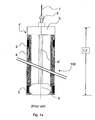
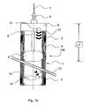
- FIG 1a and 1b illustrate in a schematic manner an overall system according to prior art and according to a preferred embodiment of the invention, respectively, in order to facilitate the description of innovative aspects.
- Both figures 1a and 1b describes a straddle packer 1 (reference numeral 1' for the prior art straddle packer), provided with a top packer element 2, a bottom packer element 3 and an anchor 4.
- Other elements known to be associated with straddle packers, such as additional anchoring modules and/or expansion joints are not shown in Figures 1a and 1b , but a person skilled in the art would easily recognise that such modules as well as other system modules as per se could be included in a preferred embodiment of the invention.
- the straddle packers 1 and 1' in Figures 1a and 1b are both prepared for setting.
- an as per se setting tool 100 comprises the top section 5, a collapsible mandrel 9, and a limited length feed-through rod 8.
- the cable head 6 and cable 7 are also illustrated to outline the complete well service tool string.
- the setting tool system for the straddle packer comprises more than one setting unit/element, and that said setting elements can be operated independent of each other.
- the as per se setting tool top section 5 is anchored to the upper sections of the straddle packer 1 by means of a collapsible mandrel 9, through the limited length feed-through rod 8.
- the feed-through rod 8 for the straddle packer 1 runs through the top section only of the straddle packer 1.
- the feature of axial length L1 of the as per se setting tool 100 being significantly shorter than the axial length L2 of the straddle packer 1 is one essential characteristic for the present invention.
- the axial length L1 of the as per se setting tool 100 is less than three quarter of the axial length L2 of the straddle packer 1.
- the axial length L1 of the as per se setting tool 100 is less than one half of the axial length L2 of the straddle packer 1.
- the axial length L1 of the as per se setting tool 100 is less than one quarter of the axial length L2 of the straddle packer 1.
- the bottom setting element 10 is used for setting of the bottom packer element 3.
- the setting tool 5 is provided with a transmitter 11 of a wireless signal that is used to transmit an activation command 12 to the bottom setting element 10 in order to set this by means of expansion.
- the bottom setting element 10 is provided with a receiver and activation unit 14 that detects the received setting command 13, translates it as known per se initiates the setting sequence of the bottom packer element 3.
- the bottom setting element 10 is a centred device, i.e. the bottom setting element 10 is substantially coaxial with the straddle packer.
- the bottom setting element 10 could be designed to disappear by means of disintegration, mechanical retraction or other means as known per se after the bottom packer element 3 is set.
- the bottom setting element 10 is built into a wall of the straddle packer 1.
- the bottom setting element 10 may be regarded as a setting tool being dependent upon the as per se setting tool 100 comprising communication means.
- the setting tool top section 5 could be of the same type as the bottom setting element 10, associated with similar communication and activation means.
- anchor(s) 4 could be associated with similar type setting element 10, associated with similar communication and activation means.
- all elements to be operated can be operated partly or totally independent from other elements to be operated, using similar type setting element 10, associated with similar communication and activation means.
- the bottom element 10 forms a seal against the inner wall of the straddle packer 1, so that fluids can not flow into the straddle packer 1 from below during deployment into a subsea well.
- This feature could be required in subsea deployment operations where pressure seals between the potentially high-pressurised wellbore and the marine environment on the outside of the wellhead might be a necessity.
- such seal requirement is achieved by means of a sealing function between the setting tool 5 and the top section of the straddle packer 1. A person skilled in the art will be familiar with ways of obtaining such a seal. For this reason, sealing elements are not shown in detail in the drawing.
- FIG 2 illustrates an alternative embodiment of the bottom setting element 10 of the straddle packer 1. Note that only a portion of the straddle packer 1 wall located at the right side of the straddle packer centre line CL is shown in figure 2 .
- the receiver 14 reads the received setting command 13.
- An electronics module 21 interrogates the receiver 14 in order to interpret registrations from the sensor/receiver 14. When there is a positive detection of an activation signal, i.e. an initiating command, the electronics emit a signal/impulse to fire a detonator 22 that again ignites a pyrotechnic charge 23 that is adapted to fit inside a slot in the wall of the straddle packer 1.
- the pyrotechnic charge 23 As the pyrotechnic charge 23 burns, it generates gas that imposes a large pressure on a piston 24.
- the piston 24 is forced downwards, and pushes a fluid 25, such as hydraulic oil, downwards.
- said fluid 25 forces a wedge-shaped element 26 downwards and forces this to set a packer element 3 against the tubing wall 27.
- the wedge shaped element 26 is replaced by means of an alternative element with similar function - i.e. to compress and support the bottom packer element 3.
- the receiver 14 and associated electronics module 21 is powered by means of a battery module 28.
- figure 2 this only illustrates one of a variety of ways of designing a system that sets (in this case) the lower packer element 3 of the straddle (or activates any element in a general application).
- Other possible methods that could be applied involve:
- Figure 3a and 3b illustrates two essential system modules of a preferred embodiment for intervening a long straddle packer 1 in a subsea well.
- FIG 3a is merely a preferred embodiment of the invention disclosed in NO 20051257 , including the following modules and components:
- Figure 3b shows the schematics of a preferred straddle packer 1 to be used in conjunction with the SDLM 31 and other seabed stack components shown in figure 3a .
- the straddle packer 1 is provided with a top packer element 2, a bottom packer element 3 and an anchor 4.
- the as per se setting tool 100 comprises a top section 5, a collapsible mandrel 9, and a limited length feed-through rod 8.
- the cable head 6 and cable 7 are also illustrated.
- a bottom setting element 10 used for setting of the bottom packer element 3.
- the "as per se" setting tool 100 top setting element 5 is provided with a transmitter 11 of a wireless signal that is used to transmit a setting command 12 (see figure 1b ) to the bottom setting element 10.
- the latter is provided with a receiver and activation unit 14 that detects the received setting command 13 (see figure 1b ) translates it and initiates the setting sequence of the bottom packer element 3.
- the bottom setting element 10 is built into the wall of straddle packer 1.
- the transmitter 11 could be located elsewhere than on the as per se setting tool 100 top setting element 5, as a module of its own or as part of other system modules. This is not further described herein.
- the transmitter 11 and receiver 14 are replaced by transceivers.
- the transceiver located in the top setting element includes a sensor that can record any indications that the setting process has taken place.
- a quartz crystal sensor that "listens" for the sound created when detonating e.g. the detonator 22 shown in figure 2 .
- Figure 4 illustrates an initial stage of a subsea intervention process from a RLWI vessel. More specifically, figure 4 illustrates the process of lowering a long straddle packer 1 assembly trough the open sea.
- a surface vessel 41 tailored for riserless well intervention (RLWI) is used in conjunction with a seabed stack 42, comprising a SDLM 31, LRP 35, hang-off spool 38 and, in this embodiment, a small section of lubricator riser 301 in order to deploy a long straddle packer 1 into the subsea well 43.
- RLWI riserless well intervention
- Steps required for flushing, pressure testing as well as monitoring parameters are not described in detail here. However, any person skilled in the art would be able to identify the need for such actions as well as the most appropriate location of related system components and also the most relevant sequence of operation with respect to these actions. Flushing, pressure testing and monitoring systems could be located anywhere on the seabed stack, for example built into the SDLM 31, the LRP 35, the hang off spool 38 or other location or combination of locations.
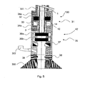
- Figure 5 illustrates the first step of system deployment, i.e. bringing the straddle packer 1 assembly from the marine environment into the pressurised well environment.
- a positioning procedure is performed in order to position the bottom packer element 3 and the bottom setting element 10 correct with respect to the test valves (gate valves) 36a and 36b and the dynamic seal 32, an anti-blowout device 33 of the SDLM 31. Said positioning is performed in a way known per se.
- the dynamic seal 32, and an anti-blowout device 33 of the SDLM 31 is engaged to the tubing wall of the straddle packer 1.
- a person skilled in the art will understand that it is of importance that no mechanical engagement is made to the bottom packer element 3 and the bottom setting element 10 in order to avoid damage to these. Hence, a proper positioning procedure is performed prior to engagement.
- the bottom packer element 3 and bottom setting element 10 are built robust enough or with a sufficient protection to allow for mechanical engagement onto these sections as well, reducing the requirements for a strict positioning of the straddle packer 1.
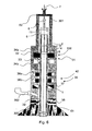
- Figure 6 illustrates the second step of system deployment. Subsequent the required flushing, pressure testing and monitoring actions, the test valves (gate valves) 36a and 36b are opened and the straddle packer 1 is lowered into the wellbore. The lowering operation is stopped prior to the anchor 4 entering the dynamic seal 32 of the SDLM 31. It is important to stop at such location as the anchor 4 might cause damage to the dynamic seal 32 if lowered into this. Also, such event could cause a breach of barrier requirements. In a preferred embodiment of the invention, positioning systems and/or mechanical or other "halt" systems are included to facilitate the correct positioning of the anchor 4 with respect to the dynamic seal 32. Upon finalising a correct positioning, the top of the cable head 6 should be fully contained inside the lubricator riser 301.
- a grease injection head 62 is mounted on top of the lubricator riser 301.
- Figure 7 illustrates an embodiment of the invention, where the dynamic seal 32 and the anti-blowout device 33 are radially disengaged from the straddle packer 1 whereupon this is run into the wellbore in order to perform the desired operation.
- Figure 8a and 8b illustrates system installation in the downhole part of the well. More specifically, figure 8a illustrates the straddle packer 1 being positioned with respect to an upper perforated section 80 by aligning the bottom packer element 3 with a non-perforated section 80' of a casing/liner 81. The non-perforated section 80' is located below said upper perforated section 80. The top packer element 2 and anchor 4 are aligned with a non-perforated section 80" of the wells casing/liner 80 above the perforated section 80. Hence, the straddle packer 1 is aligned in order to fully seal off and isolate perforation 80.
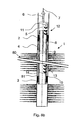
- Figure 8b illustrates the straddle packer 1 after setting/engagement of bottom packer element 3, top packer element 2 and anchor 4. Also, figure 8b illustrates emission of a wireless activation signal 12 from transmitter 11 of the setting tool 5.
- the activation signal 12 is received as signal 13 by the receiver and activation unit 14 that is located in the proximity to the bottom packer element 3.
- receiver and activation unit 14 Upon receiving a correct message 13, receiver and activation unit 14 initiates and performs the process of setting bottom packer element 3, either directly or indirectly through a bottom setting element 10 as illustrated in figures 1 and 2 .
- the straddle packer 1 assembly could comprise more than one anchor 4.
- a bottom anchor 4 would enable an installation procedure where the bottom packer element 3 and a bottom anchor (not shown) is set first, whereupon a pull test by means of applying tension to the cable 7 is performed to verify a successful setting of this part of the straddle packer 1. Subsequently, the top packer element 2 and anchor 4 can be set.
- top and bottom anchors are commonly used if an expansion joint is included in the straddle packer 1. Such expansion joints could be required if expected temperature differences in the well exceed certain limits, or if the straddle packer 1 is installed across expansion joints in the well to fix leakages. A person skilled in the art would recognise all such considerations, and no further reference is given herein.
- Figure 9 illustrates schematically an installed straddle packer 1 in a producing well after the as per se setting tool 100 with associated elements are retrieved, and production of the well is re-established. As can be seen, no fluids will now be produced from the upper perforated section 80, whereas fluids from the lower lying zone 91 are produced through straddle packer 1.
- Figure 10 illustrates retrieval of the setting tool assembly from the well.
- Figure 10 shows the as per se setting tool 100 and accessories after retrieval into the top section of the seabed stack 42. Further, the figure shows the lower end of the seabed stack.
- valves 36a and 36b are shut. Thereupon, appropriate flushing, pressure testing and monitoring actions are performed prior to disconnecting the grease injection head 62. Then, relevant steps described in the prior sections are reversed in order to retrieve the packer setting string 101 and seabed stack 42 to the surface and thereby finalizing the straddle packer installation operation.
Landscapes
- Life Sciences & Earth Sciences (AREA)
- Engineering & Computer Science (AREA)
- Geology (AREA)
- Mining & Mineral Resources (AREA)
- Physics & Mathematics (AREA)
- Environmental & Geological Engineering (AREA)
- Fluid Mechanics (AREA)
- General Life Sciences & Earth Sciences (AREA)
- Geochemistry & Mineralogy (AREA)
- Earth Drilling (AREA)
- Gasket Seals (AREA)
Claims (9)
- Dispositif pour isoler une section d'un puits de forage, le dispositif englobant une garniture d'étanchéité double (1) et un outil de pose (100) pour la mise en place sélective d'au moins un élément supérieur de la garniture d'étanchéité (2), d'au moins un élément inférieur de la garniture d'étanchéité (3) et d'au moins un dispositif d'ancrage (4) de la garniture d'étanchéité double (1), l'outil de pose (100) englobant au moins un élément de pose (10) destiné à la mise en place du au moins un élément inférieur de la garniture d'étanchéité (3), caractérisé en ce que le au moins un élément inférieur de la garniture d'étanchéité (3) est actionné indépendamment des autres éléments de pose (2) par un moyen de communication sans fil (11, 14), comprenant un émetteur (11), agencé dans l'outil de pose (100), et un récepteur (14) agencé dans l'élément de pose (10).
- Dispositif selon la revendication 1, caractérisé en ce que l'émetteur (11) et le récepteur (14) englobent un émetteur-récepteur.
- Dispositif selon la revendication 1, caractérisé en ce que la longueur axiale L1 de l'outil de pose (100) est inférieure à la longueur axiale L2 de la garniture d'étanchéité double (1).
- Dispositif selon la revendication 1, caractérisé en ce que la longueur axiale de l'outil de pose (100) représente moins des trois quarts de la longueur axiale de la garniture d'étanchéité double (1).
- Dispositif selon la revendication 1, caractérisé en ce que la longueur axiale de l'outil de pose (100) représente moins de la moitié de la longueur axiale de la garniture d'étanchéité double (1).
- Dispositif selon la revendication 1, caractérisé en ce que la longueur axiale de l'outil de pose (100) représente moins d'un quart de la longueur axiale de la garniture d'étanchéité double (1).
- Dispositif selon la revendication 1, caractérisé en ce qu'au moins un élément de pose séparé (1) est intégré dans une partie d'un corps tubulaire (27) de la garniture d'étanchéité double (1).
- Procédé d'isolation d'une section d'un puis de forage, le procédé englobant l'étape de pose d'une garniture d'étanchéité double (1) par l'intermédiaire d'un outil de pose (100) pour la mise en place sélective d'au moins un élément supérieur de la garniture d'étanchéité double (2), d'au moins un élément inférieur de la garniture d'étanchéité (3) et d'au moins un dispositif d'ancrage (4) de la garniture d'étanchéité double (1), caractérisé en ce que le procédé comprend l'étape d'actionnement du au moins un élément inférieur de la garniture d'étanchéité double (3) indépendamment des autres éléments de pose par l'intermédiaire d'un élément de pose (10) contrôlé par un moyen de communication sans fil, comprenant un émetteur (11), agencé dans l'outil de pose (100), et un récepteur (14), agencé dans l'élément de pose (10).
- Procédé selon la revendication 8, caractérisé en ce que l'outil de pose (100) a une longueur axiale considérablement inférieure à la longueur axiale de la garniture d'étanchéité double (1).
Applications Claiming Priority (2)
| Application Number | Priority Date | Filing Date | Title |
|---|---|---|---|
| NO20080453A NO332409B1 (no) | 2008-01-24 | 2008-01-24 | Anordning og fremgangsmate for a isolere en seksjon av et bronnhull |
| PCT/NO2009/000026 WO2009093913A1 (fr) | 2008-01-24 | 2009-01-22 | Dispositif et procédé pour isoler une section d'un forage |
Publications (2)
| Publication Number | Publication Date |
|---|---|
| EP2245260A1 EP2245260A1 (fr) | 2010-11-03 |
| EP2245260B1 true EP2245260B1 (fr) | 2013-09-25 |
Family
ID=40637050
Family Applications (1)
| Application Number | Title | Priority Date | Filing Date |
|---|---|---|---|
| EP09703252.8A Not-in-force EP2245260B1 (fr) | 2008-01-24 | 2009-01-22 | Dispositif et procédé pour isoler une section d'un forage |
Country Status (4)
| Country | Link |
|---|---|
| US (1) | US20100307774A1 (fr) |
| EP (1) | EP2245260B1 (fr) |
| NO (1) | NO332409B1 (fr) |
| WO (1) | WO2009093913A1 (fr) |
Cited By (1)
| Publication number | Priority date | Publication date | Assignee | Title |
|---|---|---|---|---|
| NO20191294A1 (en) * | 2019-10-29 | 2021-04-30 | Archer Oiltools As | Drill pipe string conveyed retrievable plug system |
Families Citing this family (8)
| Publication number | Priority date | Publication date | Assignee | Title |
|---|---|---|---|---|
| GB2456772A (en) * | 2008-01-22 | 2009-07-29 | Schlumberger Holdings | Deployment of a dynamic seal in an intervention procedure |
| US20100314122A1 (en) * | 2009-03-11 | 2010-12-16 | Andrea Sbordone | Method and system for subsea intervention using a dynamic seal |
| US9038740B2 (en) | 2011-11-07 | 2015-05-26 | Halliburton Energy Services, Inc. | Apparatus and method of forming a plug in a wellbore |
| WO2014084807A1 (fr) | 2012-11-27 | 2014-06-05 | Halliburton Energy Services, Inc. | Écope de trou de forage |
| US9631442B2 (en) | 2013-12-19 | 2017-04-25 | Weatherford Technology Holdings, Llc | Heave compensation system for assembling a drill string |
| US20180087336A1 (en) * | 2016-09-23 | 2018-03-29 | Baker Hughes, A Ge Company, Llc | Single trip coiled tubing conveyed electronic submersible pump and packer deployment system and method |
| WO2019241806A2 (fr) * | 2018-05-25 | 2019-12-19 | Wildcat Oil Tools, LLC | Mécanisme de déclenchement et d'actionnement électronique de fond de trou |
| EP4245959A1 (fr) * | 2022-03-16 | 2023-09-20 | Welltec A/S | Outil d'expansion filaire |
Family Cites Families (89)
| Publication number | Priority date | Publication date | Assignee | Title |
|---|---|---|---|---|
| US5186258A (en) * | 1990-09-21 | 1993-02-16 | Ctc International Corporation | Horizontal inflation tool |
| US5082062A (en) * | 1990-09-21 | 1992-01-21 | Ctc Corporation | Horizontal inflatable tool |
| US5297633A (en) * | 1991-12-20 | 1994-03-29 | Snider Philip M | Inflatable packer assembly |
| US5291947A (en) * | 1992-06-08 | 1994-03-08 | Atlantic Richfield Company | Tubing conveyed wellbore straddle packer system |
| JPH11505377A (ja) * | 1995-08-03 | 1999-05-18 | フィリップス エレクトロニクス ネムローゼ フェンノートシャップ | 半導体装置 |
| US5692564A (en) * | 1995-11-06 | 1997-12-02 | Baker Hughes Incorporated | Horizontal inflation tool selective mandrel locking device |
| JP3625598B2 (ja) * | 1995-12-30 | 2005-03-02 | 三星電子株式会社 | 液晶表示装置の製造方法 |
| US6257338B1 (en) * | 1998-11-02 | 2001-07-10 | Halliburton Energy Services, Inc. | Method and apparatus for controlling fluid flow within wellbore with selectively set and unset packer assembly |
| JP2000150861A (ja) * | 1998-11-16 | 2000-05-30 | Tdk Corp | 酸化物薄膜 |
| JP3276930B2 (ja) * | 1998-11-17 | 2002-04-22 | 科学技術振興事業団 | トランジスタ及び半導体装置 |
| US6536524B1 (en) * | 1999-04-27 | 2003-03-25 | Marathon Oil Company | Method and system for performing a casing conveyed perforating process and other operations in wells |
| TW460731B (en) * | 1999-09-03 | 2001-10-21 | Ind Tech Res Inst | Electrode structure and production method of wide viewing angle LCD |
| US6257339B1 (en) * | 1999-10-02 | 2001-07-10 | Weatherford/Lamb, Inc | Packer system |
| US6253856B1 (en) * | 1999-11-06 | 2001-07-03 | Weatherford/Lamb, Inc. | Pack-off system |
| KR20020038482A (ko) * | 2000-11-15 | 2002-05-23 | 모리시타 요이찌 | 박막 트랜지스터 어레이, 그 제조방법 및 그것을 이용한표시패널 |
| US6883610B2 (en) * | 2000-12-20 | 2005-04-26 | Karol Depiak | Straddle packer systems |
| JP3997731B2 (ja) * | 2001-03-19 | 2007-10-24 | 富士ゼロックス株式会社 | 基材上に結晶性半導体薄膜を形成する方法 |
| JP4090716B2 (ja) * | 2001-09-10 | 2008-05-28 | 雅司 川崎 | 薄膜トランジスタおよびマトリクス表示装置 |
| EP1443130B1 (fr) * | 2001-11-05 | 2011-09-28 | Japan Science and Technology Agency | Film mince monocristallin homologue a super-reseau naturel, procede de preparation et dispositif dans lequel est utilise ledit film mince monocristallin |
| JP4083486B2 (ja) * | 2002-02-21 | 2008-04-30 | 独立行政法人科学技術振興機構 | LnCuO(S,Se,Te)単結晶薄膜の製造方法 |
| US7049190B2 (en) * | 2002-03-15 | 2006-05-23 | Sanyo Electric Co., Ltd. | Method for forming ZnO film, method for forming ZnO semiconductor layer, method for fabricating semiconductor device, and semiconductor device |
| JP3933591B2 (ja) * | 2002-03-26 | 2007-06-20 | 淳二 城戸 | 有機エレクトロルミネッセント素子 |
| US7339187B2 (en) * | 2002-05-21 | 2008-03-04 | State Of Oregon Acting By And Through The Oregon State Board Of Higher Education On Behalf Of Oregon State University | Transistor structures |
| JP2004022625A (ja) * | 2002-06-13 | 2004-01-22 | Murata Mfg Co Ltd | 半導体デバイス及び該半導体デバイスの製造方法 |
| US7105868B2 (en) * | 2002-06-24 | 2006-09-12 | Cermet, Inc. | High-electron mobility transistor with zinc oxide |
| US7067843B2 (en) * | 2002-10-11 | 2006-06-27 | E. I. Du Pont De Nemours And Company | Transparent oxide semiconductor thin film transistors |
| US7066264B2 (en) * | 2003-01-13 | 2006-06-27 | Schlumberger Technology Corp. | Method and apparatus for treating a subterranean formation |
| JP4108633B2 (ja) * | 2003-06-20 | 2008-06-25 | シャープ株式会社 | 薄膜トランジスタおよびその製造方法ならびに電子デバイス |
| US7262463B2 (en) * | 2003-07-25 | 2007-08-28 | Hewlett-Packard Development Company, L.P. | Transistor including a deposited channel region having a doped portion |
| US7282782B2 (en) * | 2004-03-12 | 2007-10-16 | Hewlett-Packard Development Company, L.P. | Combined binary oxide semiconductor device |
| US7297977B2 (en) * | 2004-03-12 | 2007-11-20 | Hewlett-Packard Development Company, L.P. | Semiconductor device |
| US7145174B2 (en) * | 2004-03-12 | 2006-12-05 | Hewlett-Packard Development Company, Lp. | Semiconductor device |
| EP1737044B1 (fr) * | 2004-03-12 | 2014-12-10 | Japan Science and Technology Agency | Oxyde amorphe et transistor film mince |
| JP2006100760A (ja) * | 2004-09-02 | 2006-04-13 | Casio Comput Co Ltd | 薄膜トランジスタおよびその製造方法 |
| US7285501B2 (en) * | 2004-09-17 | 2007-10-23 | Hewlett-Packard Development Company, L.P. | Method of forming a solution processed device |
| US7298084B2 (en) * | 2004-11-02 | 2007-11-20 | 3M Innovative Properties Company | Methods and displays utilizing integrated zinc oxide row and column drivers in conjunction with organic light emitting diodes |
| US7863611B2 (en) * | 2004-11-10 | 2011-01-04 | Canon Kabushiki Kaisha | Integrated circuits utilizing amorphous oxides |
| US7791072B2 (en) * | 2004-11-10 | 2010-09-07 | Canon Kabushiki Kaisha | Display |
| US7453065B2 (en) * | 2004-11-10 | 2008-11-18 | Canon Kabushiki Kaisha | Sensor and image pickup device |
| US7829444B2 (en) * | 2004-11-10 | 2010-11-09 | Canon Kabushiki Kaisha | Field effect transistor manufacturing method |
| RU2358354C2 (ru) * | 2004-11-10 | 2009-06-10 | Кэнон Кабусики Кайся | Светоизлучающее устройство |
| EP1815530B1 (fr) * | 2004-11-10 | 2021-02-17 | Canon Kabushiki Kaisha | Transistor a effet de champ utilisant un oxyde amorphe |
| KR100998527B1 (ko) * | 2004-11-10 | 2010-12-07 | 고쿠리츠다이가쿠호진 토쿄고교 다이가꾸 | 비정질 산화물 및 전계 효과 트랜지스터 |
| US7579224B2 (en) * | 2005-01-21 | 2009-08-25 | Semiconductor Energy Laboratory Co., Ltd. | Method for manufacturing a thin film semiconductor device |
| TWI505473B (zh) * | 2005-01-28 | 2015-10-21 | 半導體能源研究所股份有限公司 | 半導體裝置,電子裝置,和半導體裝置的製造方法 |
| TWI481024B (zh) * | 2005-01-28 | 2015-04-11 | 半導體能源研究所股份有限公司 | 半導體裝置,電子裝置,和半導體裝置的製造方法 |
| US7858451B2 (en) * | 2005-02-03 | 2010-12-28 | Semiconductor Energy Laboratory Co., Ltd. | Electronic device, semiconductor device and manufacturing method thereof |
| US7948171B2 (en) * | 2005-02-18 | 2011-05-24 | Semiconductor Energy Laboratory Co., Ltd. | Light emitting device |
| US20060197092A1 (en) * | 2005-03-03 | 2006-09-07 | Randy Hoffman | System and method for forming conductive material on a substrate |
| NO323513B1 (no) * | 2005-03-11 | 2007-06-04 | Well Technology As | Anordning og fremgangsmate for havbunnsutplassering og/eller intervensjon gjennom et bronnhode pa en petroleumsbronn ved hjelp av en innforingsanordning |
| US8681077B2 (en) * | 2005-03-18 | 2014-03-25 | Semiconductor Energy Laboratory Co., Ltd. | Semiconductor device, and display device, driving method and electronic apparatus thereof |
| US7544967B2 (en) * | 2005-03-28 | 2009-06-09 | Massachusetts Institute Of Technology | Low voltage flexible organic/transparent transistor for selective gas sensing, photodetecting and CMOS device applications |
| US7645478B2 (en) * | 2005-03-31 | 2010-01-12 | 3M Innovative Properties Company | Methods of making displays |
| US8300031B2 (en) * | 2005-04-20 | 2012-10-30 | Semiconductor Energy Laboratory Co., Ltd. | Semiconductor device comprising transistor having gate and drain connected through a current-voltage conversion element |
| US7691666B2 (en) * | 2005-06-16 | 2010-04-06 | Eastman Kodak Company | Methods of making thin film transistors comprising zinc-oxide-based semiconductor materials and transistors made thereby |
| US7402506B2 (en) * | 2005-06-16 | 2008-07-22 | Eastman Kodak Company | Methods of making thin film transistors comprising zinc-oxide-based semiconductor materials and transistors made thereby |
| KR100711890B1 (ko) * | 2005-07-28 | 2007-04-25 | 삼성에스디아이 주식회사 | 유기 발광표시장치 및 그의 제조방법 |
| JP2007059128A (ja) * | 2005-08-23 | 2007-03-08 | Canon Inc | 有機el表示装置およびその製造方法 |
| JP4850457B2 (ja) * | 2005-09-06 | 2012-01-11 | キヤノン株式会社 | 薄膜トランジスタ及び薄膜ダイオード |
| JP4280736B2 (ja) * | 2005-09-06 | 2009-06-17 | キヤノン株式会社 | 半導体素子 |
| JP2007073705A (ja) * | 2005-09-06 | 2007-03-22 | Canon Inc | 酸化物半導体チャネル薄膜トランジスタおよびその製造方法 |
| JP5116225B2 (ja) * | 2005-09-06 | 2013-01-09 | キヤノン株式会社 | 酸化物半導体デバイスの製造方法 |
| US7401651B2 (en) * | 2005-09-27 | 2008-07-22 | Smith International, Inc. | Wellbore fluid saver assembly |
| EP1998373A3 (fr) * | 2005-09-29 | 2012-10-31 | Semiconductor Energy Laboratory Co, Ltd. | Dispositif de semi-conducteur disposant d'une couche de semi-conducteur d'oxyde et son procédé de fabrication |
| JP5037808B2 (ja) * | 2005-10-20 | 2012-10-03 | キヤノン株式会社 | アモルファス酸化物を用いた電界効果型トランジスタ、及び該トランジスタを用いた表示装置 |
| TWI292281B (en) * | 2005-12-29 | 2008-01-01 | Ind Tech Res Inst | Pixel structure of active organic light emitting diode and method of fabricating the same |
| US7867636B2 (en) * | 2006-01-11 | 2011-01-11 | Murata Manufacturing Co., Ltd. | Transparent conductive film and method for manufacturing the same |
| JP4977478B2 (ja) * | 2006-01-21 | 2012-07-18 | 三星電子株式会社 | ZnOフィルム及びこれを用いたTFTの製造方法 |
| US7576394B2 (en) * | 2006-02-02 | 2009-08-18 | Kochi Industrial Promotion Center | Thin film transistor including low resistance conductive thin films and manufacturing method thereof |
| US7977169B2 (en) * | 2006-02-15 | 2011-07-12 | Kochi Industrial Promotion Center | Semiconductor device including active layer made of zinc oxide with controlled orientations and manufacturing method thereof |
| KR20070101595A (ko) * | 2006-04-11 | 2007-10-17 | 삼성전자주식회사 | ZnO TFT |
| US20070252928A1 (en) * | 2006-04-28 | 2007-11-01 | Toppan Printing Co., Ltd. | Structure, transmission type liquid crystal display, reflection type display and manufacturing method thereof |
| JP4609797B2 (ja) * | 2006-08-09 | 2011-01-12 | Nec液晶テクノロジー株式会社 | 薄膜デバイス及びその製造方法 |
| JP4999400B2 (ja) * | 2006-08-09 | 2012-08-15 | キヤノン株式会社 | 酸化物半導体膜のドライエッチング方法 |
| JP4332545B2 (ja) * | 2006-09-15 | 2009-09-16 | キヤノン株式会社 | 電界効果型トランジスタ及びその製造方法 |
| JP4274219B2 (ja) * | 2006-09-27 | 2009-06-03 | セイコーエプソン株式会社 | 電子デバイス、有機エレクトロルミネッセンス装置、有機薄膜半導体装置 |
| JP5164357B2 (ja) * | 2006-09-27 | 2013-03-21 | キヤノン株式会社 | 半導体装置及び半導体装置の製造方法 |
| US7622371B2 (en) * | 2006-10-10 | 2009-11-24 | Hewlett-Packard Development Company, L.P. | Fused nanocrystal thin film semiconductor and method |
| US20080110643A1 (en) * | 2006-11-09 | 2008-05-15 | Baker Hughes Incorporated | Large bore packer and methods of setting same |
| US7772021B2 (en) * | 2006-11-29 | 2010-08-10 | Samsung Electronics Co., Ltd. | Flat panel displays comprising a thin-film transistor having a semiconductive oxide in its channel and methods of fabricating the same for use in flat panel displays |
| JP2008140684A (ja) * | 2006-12-04 | 2008-06-19 | Toppan Printing Co Ltd | カラーelディスプレイおよびその製造方法 |
| KR101303578B1 (ko) * | 2007-01-05 | 2013-09-09 | 삼성전자주식회사 | 박막 식각 방법 |
| US8207063B2 (en) * | 2007-01-26 | 2012-06-26 | Eastman Kodak Company | Process for atomic layer deposition |
| KR100851215B1 (ko) * | 2007-03-14 | 2008-08-07 | 삼성에스디아이 주식회사 | 박막 트랜지스터 및 이를 이용한 유기 전계 발광표시장치 |
| US7795613B2 (en) * | 2007-04-17 | 2010-09-14 | Toppan Printing Co., Ltd. | Structure with transistor |
| KR101325053B1 (ko) * | 2007-04-18 | 2013-11-05 | 삼성디스플레이 주식회사 | 박막 트랜지스터 기판 및 이의 제조 방법 |
| KR20080094300A (ko) * | 2007-04-19 | 2008-10-23 | 삼성전자주식회사 | 박막 트랜지스터 및 그 제조 방법과 박막 트랜지스터를포함하는 평판 디스플레이 |
| KR101334181B1 (ko) * | 2007-04-20 | 2013-11-28 | 삼성전자주식회사 | 선택적으로 결정화된 채널층을 갖는 박막 트랜지스터 및 그제조 방법 |
| DK178464B1 (da) * | 2007-10-05 | 2016-04-04 | Mærsk Olie Og Gas As | Fremgangsmåde til at forsegle en del af annulus mellem et brøndrør og en brøndboring |
-
2008
- 2008-01-24 NO NO20080453A patent/NO332409B1/no not_active IP Right Cessation
-
2009
- 2009-01-22 US US12/864,585 patent/US20100307774A1/en not_active Abandoned
- 2009-01-22 EP EP09703252.8A patent/EP2245260B1/fr not_active Not-in-force
- 2009-01-22 WO PCT/NO2009/000026 patent/WO2009093913A1/fr not_active Ceased
Cited By (3)
| Publication number | Priority date | Publication date | Assignee | Title |
|---|---|---|---|---|
| NO20191294A1 (en) * | 2019-10-29 | 2021-04-30 | Archer Oiltools As | Drill pipe string conveyed retrievable plug system |
| US11555366B2 (en) | 2019-10-29 | 2023-01-17 | Archer Oil Tools As | Drill pipe string conveyed retrievable plug system |
| NO347194B1 (en) * | 2019-10-29 | 2023-06-26 | Archer Oiltools As | Drill pipe string conveyed retrievable plug system |
Also Published As
| Publication number | Publication date |
|---|---|
| US20100307774A1 (en) | 2010-12-09 |
| EP2245260A1 (fr) | 2010-11-03 |
| WO2009093913A1 (fr) | 2009-07-30 |
| NO20080453L (no) | 2009-07-27 |
| NO332409B1 (no) | 2012-09-17 |
Similar Documents
| Publication | Publication Date | Title |
|---|---|---|
| EP2245260B1 (fr) | Dispositif et procédé pour isoler une section d'un forage | |
| US9587466B2 (en) | Cementing system for riserless abandonment operation | |
| EP2909427B1 (fr) | Dispositif et procédé d'étanchéité | |
| US9488024B2 (en) | Annulus cementing tool for subsea abandonment operation | |
| EP1339950B1 (fr) | Module de liberation de perforateur a balles automatique a passage integral | |
| EP2501895B1 (fr) | Procédé et système de revêtement d'une section de trou de forage à l'aide d'un élément tubulaire extensible | |
| EP2867446B1 (fr) | Ensemble de garniture ayant des pistons hydrostatiques doubles pour réglage sans intervention redondant | |
| WO2016100064A1 (fr) | Système de perforation pour opérations d'abandon sans colonne montante | |
| US11530586B2 (en) | Casing patch system | |
| RU2635412C2 (ru) | Контроль и передача данных из ствола скважины на поверхность | |
| US11788388B2 (en) | Casing patch system | |
| EP2867447B1 (fr) | Ensemble de garniture ayant des pistons hydrostatiques actionnés en séquence pour réglage sans intervention | |
| AU2019250350B2 (en) | Downhole straddle system | |
| US7325612B2 (en) | One-trip cut-to-release apparatus and method | |
| US8813839B2 (en) | Method of deploying and powering an electrically driven device in a well | |
| US20130098634A1 (en) | Monobore expansion system - anchored liner | |
| EA027612B1 (ru) | Вдавливающая поршневая система типа труба в трубе | |
| NO20230616A1 (en) | Casing patch system | |
| CA2731039C (fr) | Methode de deploiement et d'alimentation d'un dispositif entraine electriquement dans un puits | |
| GB2630730A (en) | Casing patch system | |
| AU2002227056A1 (en) | Full bore automatic gun release module |
Legal Events
| Date | Code | Title | Description |
|---|---|---|---|
| PUAI | Public reference made under article 153(3) epc to a published international application that has entered the european phase |
Free format text: ORIGINAL CODE: 0009012 |
|
| 17P | Request for examination filed |
Effective date: 20100805 |
|
| AK | Designated contracting states |
Kind code of ref document: A1 Designated state(s): AT BE BG CH CY CZ DE DK EE ES FI FR GB GR HR HU IE IS IT LI LT LU LV MC MK MT NL NO PL PT RO SE SI SK TR |
|
| AX | Request for extension of the european patent |
Extension state: AL BA RS |
|
| DAX | Request for extension of the european patent (deleted) | ||
| GRAP | Despatch of communication of intention to grant a patent |
Free format text: ORIGINAL CODE: EPIDOSNIGR1 |
|
| INTG | Intention to grant announced |
Effective date: 20130412 |
|
| GRAS | Grant fee paid |
Free format text: ORIGINAL CODE: EPIDOSNIGR3 |
|
| GRAA | (expected) grant |
Free format text: ORIGINAL CODE: 0009210 |
|
| AK | Designated contracting states |
Kind code of ref document: B1 Designated state(s): AT BE BG CH CY CZ DE DK EE ES FI FR GB GR HR HU IE IS IT LI LT LU LV MC MK MT NL NO PL PT RO SE SI SK TR |
|
| REG | Reference to a national code |
Ref country code: GB Ref legal event code: FG4D |
|
| REG | Reference to a national code |
Ref country code: CH Ref legal event code: EP |
|
| REG | Reference to a national code |
Ref country code: AT Ref legal event code: REF Ref document number: 633790 Country of ref document: AT Kind code of ref document: T Effective date: 20131015 |
|
| REG | Reference to a national code |
Ref country code: IE Ref legal event code: FG4D |
|
| REG | Reference to a national code |
Ref country code: DE Ref legal event code: R096 Ref document number: 602009019034 Country of ref document: DE Effective date: 20131121 |
|
| PG25 | Lapsed in a contracting state [announced via postgrant information from national office to epo] |
Ref country code: LT Free format text: LAPSE BECAUSE OF FAILURE TO SUBMIT A TRANSLATION OF THE DESCRIPTION OR TO PAY THE FEE WITHIN THE PRESCRIBED TIME-LIMIT Effective date: 20130925 Ref country code: HR Free format text: LAPSE BECAUSE OF FAILURE TO SUBMIT A TRANSLATION OF THE DESCRIPTION OR TO PAY THE FEE WITHIN THE PRESCRIBED TIME-LIMIT Effective date: 20130925 Ref country code: SE Free format text: LAPSE BECAUSE OF FAILURE TO SUBMIT A TRANSLATION OF THE DESCRIPTION OR TO PAY THE FEE WITHIN THE PRESCRIBED TIME-LIMIT Effective date: 20130925 |
|
| REG | Reference to a national code |
Ref country code: NO Ref legal event code: T2 Effective date: 20130925 |
|
| REG | Reference to a national code |
Ref country code: AT Ref legal event code: MK05 Ref document number: 633790 Country of ref document: AT Kind code of ref document: T Effective date: 20130925 |
|
| REG | Reference to a national code |
Ref country code: NL Ref legal event code: VDEP Effective date: 20130925 |
|
| REG | Reference to a national code |
Ref country code: LT Ref legal event code: MG4D |
|
| PG25 | Lapsed in a contracting state [announced via postgrant information from national office to epo] |
Ref country code: GR Free format text: LAPSE BECAUSE OF FAILURE TO SUBMIT A TRANSLATION OF THE DESCRIPTION OR TO PAY THE FEE WITHIN THE PRESCRIBED TIME-LIMIT Effective date: 20131226 Ref country code: SI Free format text: LAPSE BECAUSE OF FAILURE TO SUBMIT A TRANSLATION OF THE DESCRIPTION OR TO PAY THE FEE WITHIN THE PRESCRIBED TIME-LIMIT Effective date: 20130925 Ref country code: LV Free format text: LAPSE BECAUSE OF FAILURE TO SUBMIT A TRANSLATION OF THE DESCRIPTION OR TO PAY THE FEE WITHIN THE PRESCRIBED TIME-LIMIT Effective date: 20130925 Ref country code: FI Free format text: LAPSE BECAUSE OF FAILURE TO SUBMIT A TRANSLATION OF THE DESCRIPTION OR TO PAY THE FEE WITHIN THE PRESCRIBED TIME-LIMIT Effective date: 20130925 |
|
| PG25 | Lapsed in a contracting state [announced via postgrant information from national office to epo] |
Ref country code: BE Free format text: LAPSE BECAUSE OF FAILURE TO SUBMIT A TRANSLATION OF THE DESCRIPTION OR TO PAY THE FEE WITHIN THE PRESCRIBED TIME-LIMIT Effective date: 20130925 |
|
| PG25 | Lapsed in a contracting state [announced via postgrant information from national office to epo] |
Ref country code: EE Free format text: LAPSE BECAUSE OF FAILURE TO SUBMIT A TRANSLATION OF THE DESCRIPTION OR TO PAY THE FEE WITHIN THE PRESCRIBED TIME-LIMIT Effective date: 20130925 Ref country code: IS Free format text: LAPSE BECAUSE OF FAILURE TO SUBMIT A TRANSLATION OF THE DESCRIPTION OR TO PAY THE FEE WITHIN THE PRESCRIBED TIME-LIMIT Effective date: 20140125 Ref country code: CZ Free format text: LAPSE BECAUSE OF FAILURE TO SUBMIT A TRANSLATION OF THE DESCRIPTION OR TO PAY THE FEE WITHIN THE PRESCRIBED TIME-LIMIT Effective date: 20130925 Ref country code: SK Free format text: LAPSE BECAUSE OF FAILURE TO SUBMIT A TRANSLATION OF THE DESCRIPTION OR TO PAY THE FEE WITHIN THE PRESCRIBED TIME-LIMIT Effective date: 20130925 Ref country code: NL Free format text: LAPSE BECAUSE OF FAILURE TO SUBMIT A TRANSLATION OF THE DESCRIPTION OR TO PAY THE FEE WITHIN THE PRESCRIBED TIME-LIMIT Effective date: 20130925 Ref country code: RO Free format text: LAPSE BECAUSE OF FAILURE TO SUBMIT A TRANSLATION OF THE DESCRIPTION OR TO PAY THE FEE WITHIN THE PRESCRIBED TIME-LIMIT Effective date: 20130925 |
|
| PGFP | Annual fee paid to national office [announced via postgrant information from national office to epo] |
Ref country code: NO Payment date: 20140127 Year of fee payment: 6 |
|
| PG25 | Lapsed in a contracting state [announced via postgrant information from national office to epo] |
Ref country code: AT Free format text: LAPSE BECAUSE OF FAILURE TO SUBMIT A TRANSLATION OF THE DESCRIPTION OR TO PAY THE FEE WITHIN THE PRESCRIBED TIME-LIMIT Effective date: 20130925 Ref country code: PL Free format text: LAPSE BECAUSE OF FAILURE TO SUBMIT A TRANSLATION OF THE DESCRIPTION OR TO PAY THE FEE WITHIN THE PRESCRIBED TIME-LIMIT Effective date: 20130925 Ref country code: ES Free format text: LAPSE BECAUSE OF FAILURE TO SUBMIT A TRANSLATION OF THE DESCRIPTION OR TO PAY THE FEE WITHIN THE PRESCRIBED TIME-LIMIT Effective date: 20130925 Ref country code: CY Free format text: LAPSE BECAUSE OF FAILURE TO SUBMIT A TRANSLATION OF THE DESCRIPTION OR TO PAY THE FEE WITHIN THE PRESCRIBED TIME-LIMIT Effective date: 20130925 |
|
| REG | Reference to a national code |
Ref country code: DE Ref legal event code: R097 Ref document number: 602009019034 Country of ref document: DE |
|
| PG25 | Lapsed in a contracting state [announced via postgrant information from national office to epo] |
Ref country code: PT Free format text: LAPSE BECAUSE OF FAILURE TO SUBMIT A TRANSLATION OF THE DESCRIPTION OR TO PAY THE FEE WITHIN THE PRESCRIBED TIME-LIMIT Effective date: 20140127 |
|
| PGFP | Annual fee paid to national office [announced via postgrant information from national office to epo] |
Ref country code: GB Payment date: 20140122 Year of fee payment: 6 |
|
| PLBE | No opposition filed within time limit |
Free format text: ORIGINAL CODE: 0009261 |
|
| REG | Reference to a national code |
Ref country code: DE Ref legal event code: R119 Ref document number: 602009019034 Country of ref document: DE |
|
| STAA | Information on the status of an ep patent application or granted ep patent |
Free format text: STATUS: NO OPPOSITION FILED WITHIN TIME LIMIT |
|
| PG25 | Lapsed in a contracting state [announced via postgrant information from national office to epo] |
Ref country code: MC Free format text: LAPSE BECAUSE OF FAILURE TO SUBMIT A TRANSLATION OF THE DESCRIPTION OR TO PAY THE FEE WITHIN THE PRESCRIBED TIME-LIMIT Effective date: 20130925 Ref country code: LU Free format text: LAPSE BECAUSE OF FAILURE TO SUBMIT A TRANSLATION OF THE DESCRIPTION OR TO PAY THE FEE WITHIN THE PRESCRIBED TIME-LIMIT Effective date: 20140122 Ref country code: IT Free format text: LAPSE BECAUSE OF FAILURE TO SUBMIT A TRANSLATION OF THE DESCRIPTION OR TO PAY THE FEE WITHIN THE PRESCRIBED TIME-LIMIT Effective date: 20130925 |
|
| REG | Reference to a national code |
Ref country code: CH Ref legal event code: PL |
|
| 26N | No opposition filed |
Effective date: 20140626 |
|
| PG25 | Lapsed in a contracting state [announced via postgrant information from national office to epo] |
Ref country code: DK Free format text: LAPSE BECAUSE OF FAILURE TO SUBMIT A TRANSLATION OF THE DESCRIPTION OR TO PAY THE FEE WITHIN THE PRESCRIBED TIME-LIMIT Effective date: 20130925 |
|
| REG | Reference to a national code |
Ref country code: DE Ref legal event code: R097 Ref document number: 602009019034 Country of ref document: DE Effective date: 20140626 |
|
| REG | Reference to a national code |
Ref country code: DE Ref legal event code: R119 Ref document number: 602009019034 Country of ref document: DE Effective date: 20140801 |
|
| PG25 | Lapsed in a contracting state [announced via postgrant information from national office to epo] |
Ref country code: CH Free format text: LAPSE BECAUSE OF NON-PAYMENT OF DUE FEES Effective date: 20140131 Ref country code: DE Free format text: LAPSE BECAUSE OF NON-PAYMENT OF DUE FEES Effective date: 20140801 Ref country code: LI Free format text: LAPSE BECAUSE OF NON-PAYMENT OF DUE FEES Effective date: 20140131 |
|
| REG | Reference to a national code |
Ref country code: FR Ref legal event code: ST Effective date: 20140930 |
|
| REG | Reference to a national code |
Ref country code: IE Ref legal event code: MM4A |
|
| PG25 | Lapsed in a contracting state [announced via postgrant information from national office to epo] |
Ref country code: FR Free format text: LAPSE BECAUSE OF NON-PAYMENT OF DUE FEES Effective date: 20140131 |
|
| PG25 | Lapsed in a contracting state [announced via postgrant information from national office to epo] |
Ref country code: IE Free format text: LAPSE BECAUSE OF NON-PAYMENT OF DUE FEES Effective date: 20140122 |
|
| GBPC | Gb: european patent ceased through non-payment of renewal fee |
Effective date: 20150122 |
|
| PG25 | Lapsed in a contracting state [announced via postgrant information from national office to epo] |
Ref country code: NO Free format text: LAPSE BECAUSE OF NON-PAYMENT OF DUE FEES Effective date: 20150131 Ref country code: GB Free format text: LAPSE BECAUSE OF NON-PAYMENT OF DUE FEES Effective date: 20150122 |
|
| PG25 | Lapsed in a contracting state [announced via postgrant information from national office to epo] |
Ref country code: MT Free format text: LAPSE BECAUSE OF FAILURE TO SUBMIT A TRANSLATION OF THE DESCRIPTION OR TO PAY THE FEE WITHIN THE PRESCRIBED TIME-LIMIT Effective date: 20130925 |
|
| PG25 | Lapsed in a contracting state [announced via postgrant information from national office to epo] |
Ref country code: BG Free format text: LAPSE BECAUSE OF FAILURE TO SUBMIT A TRANSLATION OF THE DESCRIPTION OR TO PAY THE FEE WITHIN THE PRESCRIBED TIME-LIMIT Effective date: 20130925 |
|
| PG25 | Lapsed in a contracting state [announced via postgrant information from national office to epo] |
Ref country code: TR Free format text: LAPSE BECAUSE OF FAILURE TO SUBMIT A TRANSLATION OF THE DESCRIPTION OR TO PAY THE FEE WITHIN THE PRESCRIBED TIME-LIMIT Effective date: 20130925 Ref country code: HU Free format text: LAPSE BECAUSE OF FAILURE TO SUBMIT A TRANSLATION OF THE DESCRIPTION OR TO PAY THE FEE WITHIN THE PRESCRIBED TIME-LIMIT; INVALID AB INITIO Effective date: 20090122 |
|
| PG25 | Lapsed in a contracting state [announced via postgrant information from national office to epo] |
Ref country code: MK Free format text: LAPSE BECAUSE OF FAILURE TO SUBMIT A TRANSLATION OF THE DESCRIPTION OR TO PAY THE FEE WITHIN THE PRESCRIBED TIME-LIMIT Effective date: 20130925 |