EP2246466A1 - Flachstrickmaschine sowie betriebsverfahren für beweglichen träger in der flachstrickmaschine - Google Patents
Flachstrickmaschine sowie betriebsverfahren für beweglichen träger in der flachstrickmaschine Download PDFInfo
- Publication number
- EP2246466A1 EP2246466A1 EP08864134A EP08864134A EP2246466A1 EP 2246466 A1 EP2246466 A1 EP 2246466A1 EP 08864134 A EP08864134 A EP 08864134A EP 08864134 A EP08864134 A EP 08864134A EP 2246466 A1 EP2246466 A1 EP 2246466A1
- Authority
- EP
- European Patent Office
- Prior art keywords
- carriage
- carrier
- knitting
- electric power
- shut
- Prior art date
- Legal status (The legal status is an assumption and is not a legal conclusion. Google has not performed a legal analysis and makes no representation as to the accuracy of the status listed.)
- Granted
Links
Images


Classifications
-
- D—TEXTILES; PAPER
- D04—BRAIDING; LACE-MAKING; KNITTING; TRIMMINGS; NON-WOVEN FABRICS
- D04B—KNITTING
- D04B35/00—Details of, or auxiliary devices incorporated in, knitting machines, not otherwise provided for
- D04B35/10—Indicating, warning, or safety devices, e.g. stop motions
-
- D—TEXTILES; PAPER
- D04—BRAIDING; LACE-MAKING; KNITTING; TRIMMINGS; NON-WOVEN FABRICS
- D04B—KNITTING
- D04B15/00—Details of, or auxiliary devices incorporated in, weft knitting machines, restricted to machines of this kind
- D04B15/94—Driving-gear not otherwise provided for
- D04B15/96—Driving-gear not otherwise provided for in flat-bed knitting machines
Definitions
- the present invention relates to a flatbed knitting machine having a self-moving carrier for feeding a knitting yarn when a knit fabric is knitted with knitting needles driven by a carriage which moves along a needle bed, and to a control method for the self-moving carrier in the flatbed knitting machine.
- the flatbed knitting machine for knitting a knit fabric with the knitting needles driven by the carriage moving in reciprocation along the needle bed often employs a system for allowing the carriage to mechanically pull the carrier for feeding the knitting yarn.
- the carriage mounts cams adapted to act upon the knitting needles, and the carrier is pulled so that its positional relation with the cams can be kept constant. When the pulling of the carrier by the carriage is released, the carrier comes to a stop.
- the self-moving carriers are moved separately along the needle bed without being pulled by the carriage (See Patent Citation 1, for example).
- the self-moving carrier is used to feed the knitting yarn, since the self-moving carrier can be retracted or returned by its own movement in the knitting of intarsia and the like, the need to drive the carriage for the kick-back operation can be eliminated to avoid decrease in knitting efficiency.
- this self-moving carrier a variety of knitting methods can be provided, including e.g. plating wherein a face yarn and a back yarn are fed from two carriers to one cam with a predetermined phase difference.
- a main motor for the flatbed knitting machine is used as a driving source for the carriage.
- the main motor is controlled via e.g. a servo drive system.
- a position of the carriage is detected directly from its position relative to the needle bed or frame of the flatbed knitting machine or indirectly from rotation of the main motor and the like.
- a position of the self-moving carrier which is in the middle of moving is also detected and is synchronized with the position of the carriage so as to fall within a certain range.
- the flatbed knitting machine is provided with a stop switch for stopping the knitting operation.
- a driving power supply for driving the main motor and others for driving the carriage is shut off.
- the electric power supply for driving the carriage is shut off due to electric power failure or by operation of a power shutdown device, as well.
- the flatbed knitting machine having the self-moving carrier requires that the carriage and the carrier be constantly synchronized to ensure the yarn feed for the reliable knitting and production of a variety of knit fabrics.
- the carriage and the carrier are not synchronized.
- the carriage comes free from the control of the servo driver, so that it gradually slows down and eventually stops. If moving at a speed of e.g. 1m/s for the knitting of the knit fabric, the carriage will move over the order of 100mm until it comes to a stop.
- the carrier comes to a stop, so that there occurs a zone where the knitting yarn is not fed from the carrier, while only the knitting needles are driven for knitting. In that zone, no new loops are formed with the knitting needles, resulting in a press-off stitch fault.
- a zone where in association with decrease or increase in speed of the carriage when reversed in moving direction, the carrier is brought to a halt to allow only the carriage to move.
- a sequence is performed to allow only the carriage to be accelerated in this zone and then allow the carriage to be synchronized with the carrier, while also allowing the carrier to move.
- the carriage cannot stop immediately.
- the stop position of the carriage is in the zone in which the carrier as well is moved, the carriage already passes past the position at which the carrier starts moving, when restarting to move after release of the shut-off of the electric power. This causes the press-off stitch fault.
- the present invention provides a flatbed knitting machine provided with a carriage which moves along a needle bed on which knitting needles are arranged in parallel and mounts a cam to allow the knitting needles to be selectively driven for knitting, and a carrier which moves separately from the carriage by its own movement, while being synchronized with the carriage in position to feed a knitting yarn to the knitting needles driven for the knitting, the flatbed knitting machine comprising:
- the present invention provides the flatbed knitting machine further comprising a memory for storing positions of said carriage on a time-series basis, wherein said controller operates to derive a predicted position of the carriage based on the positions of the carriage stored in the memory and control the carrier to move with said synchronized position with the predicted position being kept.
- the present invention provides the flatbed knitting machine, wherein said controller controls said carriage so that at the start-up of the carriage, only the carriage can be accelerated alone until a prescribed condition for start-up moving the carrier is satisfied, and then controls said carrier to start up so that it can be synchronized with the carriage while moving, followed by controlling the carrier so that when the electric power supply for driving the carriage is shut off in the process of only the carriage being accelerated alone, the carrier can be started up to be synchronized with the carriage while moving, if the condition for start-up moving the carrier is satisfied until carriage stops.
- the present invention provides a control method for controlling movement of a self-moving carrier in a flatbed knitting machine provided with a carriage which moves along a needle bed on which knitting needles are arranged in parallel and mounts a cam to allow the knitting needles to be selectively driven for knitting, and a carrier which moves separately from the carriage by its own movement, while being synchronized with the carriage in position to feed a knitting yarn to the knitting needles driven for the knitting, when electric power supply to drive the carriage is shut off in a process of movement of the carriage, wherein even when the electric power supply to drive the carriage is shut off, a position of the carriage is to be capable of detecting at least until the carriage stops, and wherein when the electric power supply to drive the carriage is shut off in the process of the carriage and the carrier being synchronized with each other while moving, the movement of the carrier is controlled so that the synchronized position of the carrier with the position of the carriage can be kept until the carriage stops.
- the controller controls the movement of the carrier so that the synchronized position of the carrier with the position of the carriage can be kept until the carriage stops.
- the controller operates to derive a predicted position of the carriage based on the positions of the carriage stored in the memory on a time-series basis.
- the carrier can be controlled so that its position can be promptly synchronized with the predicted position of the carriage.
- the carrier is synchronized with the carriage, if the condition for start-up moving the carrier is satisfied by the time the carriage stops. Hence, the knitting can be restarted properly after release of the shut-off of the electric power supply to drive the carriage.
- the movement of the carrier is controlled so that the synchronized position of the carrier with the position of the carriage can be kept until the carriage stops.
- This can provide the result that even when the electric power supply to drive the carriage is shut off by e.g. the operation of the stop switch, the synchronization between the carriage and the self-moving carrier can be kept. This can enable the knitting to be restarted properly after the release of the shut-off of the electric power supply.
- Fig. 1 shows a schematic electric structure of a flatbed knitting machine 1 as a certain embodiment of the present invention.
- the flatbed knitting machine 1 knitting needles arranged in parallel on a needle bed 2 are driven selectively by cams mounted on a carriage 3 to knit a knit fabric.
- the carriage 3 is driven to move in reciprocation in a right and left direction as viewed in the drawing figure.
- the right and left direction defined here corresponds to a longitudinal direction of the needle bed 2.
- the carriage 3 is connected to a timing belt 4 extending between both lengthwise ends of the needle bed 2.
- the timing belt 4 is driven via a drive pulley 5 at one lengthwise end of the needle bed 2.
- the drive pulley 5 is mounted on an output shaft of a carriage drive motor 6. A rotation angle of the output shaft is detected by an encoder 7.
- the needle bed 2 usually are provided to form a pair, and the paired needle beds are arranged opposite to each other across a needle bed gap 8 into or from which ends of the knitting needles are advanced or retracted.
- the other needle bed, not shown, arranged across the needle bed gap 8 has also the same structure as the needle bed 2.
- a carriage rail 9 is arranged to support the carriage 3 so that the carriage 3 can move in reciprocation in a longitudinal direction of the needle bed 2.
- a controller 10 is provided to control the movement of the carriage 3.
- the controller 10 including CPU controls the flatbed knitting machine 1 provided with the carriage 3 in accordance with preset programs.
- a self-moving carrier 13 equipped with a yarn feeder 12 is moves in reciprocation along a yarn guide rail 11 arranged over the needle bed gap 8.
- a knitting yarn used for the knitting of a knit fabric is fed from the yarn feeder 12 to the knitting needles.
- the carrier 13 is connected to a timing belt 14 extending between both ends of the yarn guide rail 11.
- the timing belt 14 is driven via a drive pulley 15 at one lengthwise end of the yarn guide rail 11.
- the drive pulley 15 is mounted on an output shaft of a carrier drive motor 16. A rotation angle of the output shaft is detected by an encoder 17.
- Data corresponding to rotation angles of the output shaft of the carriage drive motor 6 detected by the encoder 7 and data corresponding to rotation angles of the output shaft of the carrier drive motor 16 detected by the encoder 17 are entered into the controller 10. Based on the data entered, the controller 10 controls the carriage 3 and the carrier 13 so that they can be synchronized with each other to keep their positional relation constant.
- the carriage 3 could mount two or more cams for driving the knitting needles. If the carriage 3 mounts two or more cams for driving the knitting needles, multiple knitting drive can be performed in a single stroke of one reciprocating movement of the carriage 3. In this case, two or more carriers 13 are moved in synchronization to correspond in position to the respective cams. In the knitting of plating, the two or more carriers 13 are moved in synchronization so that one used for a front yarn and another used for a back yarn can be in a shifted positional relation with the single cam mounted on the carriage 3.
- An electric power to drive the carriage drive motor 6 is supplied to a carriage servo 23 from e.g. a commercial alternating-current source 20 as an external power source through a backup device 21 serving as a power source for the flatbed knitting machine and through a stop switch 22.
- the carriage servo 23 is used for servo drive of the carriage drive motor 6.
- the backup device 21 includes a large-capacity condenser and a magnetic circuit breaker, and the electric power is supplied to the stop switch 22 through the magnetic circuit breaker.
- the magnetic circuit breaker is tripped and the electric driving power supplied to the carriage drive motor 6 through the carriage servo 23 is shut off.
- the stop switch 21 is operated due to an emergency situation or other circumstances in the process of receiving the electric power, as well, the electric power supply to drive the carriage 3 is shut off.
- the electric power is supplied from the backup device 21 to a load which is lighter than the carriage 3 including the carrier 13, as well, including, for example, the carrier servo 24 used for the servo drive of the carrier motor 16, and the controller 10.
- the backup power stored in the condenser situated within the backup device 21 is supplied to such a load.
- the condenser has a capacity enough large for the back-up power to be supplied on a time scale of seconds.
- the carrier servo 24 can be structured so that even when the electric power supply for driving is shut off, the electric power can be regenerated from the carrier motor 16 to extend the electric power supply by several seconds until the electric power supply is shutoff.
- the controller 10 controls the carrier 13 to keep the synchronization between the position of the carrier 13 and that of the carriage 3, as mentioned later.
- the controller 10 is structured so that even when the electric power received from the commercial alternating-current source 20 is shut off, the power can be supplied from the backup device 21 to the controller 10 during at least this controlling process.
- the carrier servo 24 to drive the carrier motor 16 may be structured to regenerate the electric power so as to increase the time until the carrier motor 16 stops, as previously mentioned.
- the controller 10 is provided with a memory 25 for the purpose of proper control on the synchronization between the position of the carriage 3 and the position of the carrier 13.
- the data on the positions of the carriage 3 are stored in the memory 2 5 at regular time intervals, e.g. once for every 1ms.
- the memory 25 includes a given region allocated to store the data on the positions of the carriage 3. When the data is fully stored in the entire region, the oldest data stored is overwritten by entering new data in that region.
- the carriage drive motor 6 and the carrier drive motor 16 are operated via the carriage servo 23 and carrier servo 24, respectively, under control of the controller 10.
- the electric power supplied from the main source 20 of electric power is supplied to the carriage drive motor 6 by the servo driver 25 under the control of the controller 10.
- the carriage servo 23 uses the regenerative electric power generated by the carriage drive motor 6 as an electric generator, to keep the state in which the rotation angle can be detected by the encoder 7.
- a backup power source which can supply the electric power for longer hours than the backup device 21 from which the backup power is supplied, and a nonvolatile flash memory are used for the memory 25.
- the data on the positions of the carriage 3 held during halts of the flatbed knitting machine 1 can be read out from this memory 25 even at the restart of the flatbed knitting machine 1 after halted.
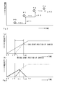
- Fig. 2 shows a concept of a manner that a position of the carriage 3, decreased in speed for example after operation of the emergency stop switch 21, is predicted based on the data on past positions of the carriage 3 stored in memory 25 of Fig. 1 .
- the data indicating the past positions of the carriage 3 are stored in the memory 25 on a time-series basis of e.g. once for every 1ms.
- the position of the carriage 3 is calculated based on the rotation angle of the output shaft of the carriage drive motor 6 output from the encoder 7.
- a linear encoder or the like which can do the position detection directly along the needle bed 2, the carriage rail 9, or the like may be provided to detect that position.
- the memory 25 has a storage area large enough to store the data on at least three positions required to predict the following points.
- a 1ms-later predicated position is derived as P3 from the data on three past positions of 3ms, P0, P1 and P2, including the present position.
- P2 is the present position
- P1 is a 1ms past position
- P0 is a 2ms past position
- dP1 is a difference between P0 and P1
- dP2 is a difference between P1 and P2
- dP ⁇ 2 P ⁇ 2 - P ⁇ 1
- the controller 10 of Fig. 1 controls the carriage drive motor 6 and the carrier drive motor 16 so that the position of the carriage 3 and the position(s) of the one or more than one carriers 13 are synchronized, keeping their positional relation constant.
- the carriage 3 is controlled by the carriage drive motor 6 to be increased or decreased in speed so as to properly move in reciprocation along the needle bed 2 within a range determined depending on a knitting width of a knitted fabric to be knitted.
- the controller 10 When the electric power supply to the carriage servo 23 is shut off in the state in which the position of the carrier 13 is synchronized with the position of the carriage 3, the controller 10 operates to derive a predicted position of the carriage 13 and control the position of the carrier 13 to be synchronized with the predicted position.
- Fig. 3 shows a concept of a manner to control the carriage 3 when the electric power supply to drive the carriage is shut off at the start-up of the carriage 3. It is usual that after being moved to e.g. a position on the outer side of the one end of the knitting width end and on the outer side of the carrier 13, the carriage 3 is reversed in direction. According to the start-up sequence of the carriage after reversed in direction, at the time of t0, the carriage in the resting state starts moving toward the other end of the knitting width at a constant speed, as shown in solid line in Fig. 3(a) . At that time, the carrier 13 is on standby at a position on the outer side of the one end of the knitting width and near the end of the knitting width.
- the carriage 3 Since the carriage 3 is moved alone until the time of t1, it is needless to say that the carriage 3 is not synchronized with the carrier 13 until then. At the time of t1, the carriage 3 reaches a carrier start position where the carrier 13 starts moving, and the carrier 13 starts moving to the other side of the knitting width, as shown in broken line. Since the carrier 13 smaller in load than the carriage 3 can be accelerated at a more rapid pace, the carrier 13 reaches the velocity equal to that of the carriage 3 at the time of t2 and then keeps its synchronized positional relation with the carriage 3. When being synchronized with the carrier 13, the carriage 3 can drive the knitting needles into action to knit a knit fabric using a knitting yarn fed to the knitting needles from the yarn feeder 12 of the carrier 13. When the electric power supply to the carriage servo 23 is shut off after the synchronization, the control may be exercised, while a predicted position of the carriage 3 is derived, as shown in Fig. 2 .
- a possible shut-off of the electric power supply to the carriage servo 23 may occur between the time t1 and the time t2, as well.
- the acceleration of the carriage 3 proceeding from the time of t0 is interrupted at the time of tx, as indicated in bold solid line.
- the controller 10 controls the carrier 13 so that the position of the carrier 13 can be promptly synchronized with the predicted position of the carriage 3 after the time of tx, as shown in bold broken line.
- the carrier 13 Since the carrier 13 is smaller in load, the carrier 13 can be accelerated at a further rapid pace. Since the carriage 13 is decreased in speed after the time of tx, the synchronization can be obtained quickly. After synchronized, the carrier 13 can be controlled so that its position can be aligned with the predicted position, while the predicted position of the carriage 3 is derived.
- a possible shut-off of the electric power supply to the carriage servo 23 may occur between the time t0 and the time t1 while the carriage 3 is accelerated alone.
- a position at which the carriage 3 decelerated due to the shut-off of the power supply comes to a stop does not arrive at the carrier start-up position, there is no need to start up the carrier 13.
- the carrier 13 need not be controlled for synchronization until the shut-off of the power supply is released to restart the operation and the carriage 3 arrives at the carrier start-up position.
- the carrier 13 may be controlled so that its position can be immediately synchronized with the predicted position of the carriage 3, as in the case of the possible shut-off of the electric power supply which may occur between the time t1 and the time t2, as shown in Fig. 3(b) .
- Fig. 4 shows overall control procedures of the carrier 13 by the controller 10 described above.
- the present position of the carriage 3 is stored in the memory 25.
- decision is made whether the stop switch 22 was pushed, or whether the commercial alternating-current source 20 was shut off due to the electric power failure. This decision is made by for example monitoring voltage of the carriage servo 23 on the input side.
- a target position of the carrier 13 with respect to a 1ms-later target position of the carriage 3 is calculated in the step s3.
- the target position of the carriage 3 can be set in accordance with the sequence for the operations including for example acceleration at start-up, constant-speed motion after acceleration, as shown in solid line extending from the time t0 in Fig. 3(a), and deceleration at the interruption, not shown.
- the calculated target position of the carrier 13 is output to the carrier servo 24 and the carrier drive motor 16 is controlled.
- a series of procedures between the steps s1 and s4 are repeated to control the carriage 3 and the carrier 13 so that they can be synchronized with each other, while moving.
- the 1ms-later position of the carriage 3 is predicted in the way of thinking as shown in Fig. 2 , in the step s5.
- decision is made whether the carrier 13 and the carriage 3 are not yet synchronized with each other.
- the target position of the carrier 13 with respect to the 1ms-later predicated position of the carriage 3 is calculated in the step s7, then going to the step s4.
- the state of before t1 of Fig. 3(a) is decided as the carrier 13 and the carriage 3 being not yet synchronized, in the step s6.
- This state corresponds to, for example, the state that the carriage 3 passed past the end of the knitting width to be reversed in travelling direction.
- decision is made in the step s8 whether the predicted position of the carriage 3 passed past the carrier start-up position.
- the target position of the carrier 13 with respect to the 1ms-later predicted position of the carriage 3 is calculated in the step s9. This corresponds to the way of synchronizing the carrier 13 and the carriage 3 with each other instantly.
- the target position of the carrier 13 is not calculated and is not set in the step s8, then going to the step s4.
- the step s4 since the target position of the carrier to be output is not presented, only the carriage 3 is moved, while the carrier 13 remains stationary.
Landscapes
- Engineering & Computer Science (AREA)
- Textile Engineering (AREA)
- Knitting Machines (AREA)
Applications Claiming Priority (2)
| Application Number | Priority Date | Filing Date | Title |
|---|---|---|---|
| JP2007333189 | 2007-12-25 | ||
| PCT/JP2008/003943 WO2009081583A1 (ja) | 2007-12-25 | 2008-12-25 | 横編機および横編機での自走式キャリアの制御方法 |
Publications (3)
| Publication Number | Publication Date |
|---|---|
| EP2246466A1 true EP2246466A1 (de) | 2010-11-03 |
| EP2246466A4 EP2246466A4 (de) | 2013-01-16 |
| EP2246466B1 EP2246466B1 (de) | 2014-11-12 |
Family
ID=40800900
Family Applications (1)
| Application Number | Title | Priority Date | Filing Date |
|---|---|---|---|
| EP08864134.5A Not-in-force EP2246466B1 (de) | 2007-12-25 | 2008-12-25 | Flachstrickmaschine sowie betriebsverfahren für beweglichen träger in der flachstrickmaschine |
Country Status (4)
| Country | Link |
|---|---|
| EP (1) | EP2246466B1 (de) |
| JP (1) | JP5330265B2 (de) |
| CN (1) | CN101910491B (de) |
| WO (1) | WO2009081583A1 (de) |
Families Citing this family (3)
| Publication number | Priority date | Publication date | Assignee | Title |
|---|---|---|---|---|
| JP5541127B2 (ja) * | 2010-12-08 | 2014-07-09 | 株式会社リコー | インクジェット記録装置 |
| CN103993417B (zh) * | 2014-05-22 | 2016-01-06 | 浙江恒强科技股份有限公司 | 一种横机自跑式纱嘴的控制系统及方法 |
| KR20230132830A (ko) | 2021-01-22 | 2023-09-18 | 가부시키가이샤 시마세이키 세이사쿠쇼 | 인버스 플레이팅용 보정 데이터의 생성방법 및 생성시스템 |
Family Cites Families (6)
| Publication number | Priority date | Publication date | Assignee | Title |
|---|---|---|---|---|
| JPH0390665A (ja) * | 1989-01-06 | 1991-04-16 | Ikenaga:Kk | 横編機の柄出制御装置 |
| CH686089A5 (fr) * | 1991-08-02 | 1995-12-29 | Steiger Sa Atelier Constr | Machine a tricoter rectiligne. |
| JPH08127948A (ja) * | 1994-10-31 | 1996-05-21 | Shima Seiki Mfg Ltd | 編機のキャリアの制御方法とその装置 |
| JP2001003245A (ja) * | 1999-06-16 | 2001-01-09 | Tsudakoma Corp | 編機における編成部材駆動用のリニアモータ制御装置 |
| JP3511012B2 (ja) * | 2001-01-18 | 2004-03-29 | 株式会社島精機製作所 | 横編機における停電時のバックアップシステム |
| JP2004076172A (ja) * | 2002-08-12 | 2004-03-11 | Precision Fukuhara Works Ltd | 丸編機の給糸制御方法および給糸制御装置 |
-
2008
- 2008-12-25 WO PCT/JP2008/003943 patent/WO2009081583A1/ja not_active Ceased
- 2008-12-25 CN CN2008801228624A patent/CN101910491B/zh not_active Expired - Fee Related
- 2008-12-25 JP JP2009546953A patent/JP5330265B2/ja not_active Expired - Fee Related
- 2008-12-25 EP EP08864134.5A patent/EP2246466B1/de not_active Not-in-force
Also Published As
| Publication number | Publication date |
|---|---|
| CN101910491B (zh) | 2012-07-18 |
| EP2246466B1 (de) | 2014-11-12 |
| CN101910491A (zh) | 2010-12-08 |
| WO2009081583A1 (ja) | 2009-07-02 |
| EP2246466A4 (de) | 2013-01-16 |
| JPWO2009081583A1 (ja) | 2011-05-06 |
| JP5330265B2 (ja) | 2013-10-30 |
Similar Documents
| Publication | Publication Date | Title |
|---|---|---|
| CN101223094B (zh) | 用于确保恒定张力纱线喂入纺织机械的双控制回路方法和装置 | |
| EP2246466B1 (de) | Flachstrickmaschine sowie betriebsverfahren für beweglichen träger in der flachstrickmaschine | |
| KR101861196B1 (ko) | 편물 라인에서 사고로 인한 실의 정지를 검출하기 위한 방법 및 장치 | |
| EP2206815A1 (de) | Flachstrickmaschine und fadenführungsverfahren | |
| JP2000008257A (ja) | 自由に選択可能なパタ―ンリピ―トを有する編布の製造方法およびたて編機 | |
| EP2336411A1 (de) | Flachstrickmaschine | |
| JPS5947063B2 (ja) | たて編機 | |
| RU2003115441A (ru) | Способ эксплуатации ткацкого станка с зевообразовательным механизмом | |
| EP0709506B1 (de) | Vorrichtung und Verfahren zum Steuern eines Fadenführerkastens an einer Strickmaschine | |
| US5819558A (en) | Method of lowering the yarn height for knitting single knit fabric | |
| EP0916759A2 (de) | Verfahren und Vorrichtung zum Steuern einer Flachstrickmaschine | |
| EP2441868B1 (de) | Garnzufuhrvorrichtung und garnzufuhrverfahren für eine strickmaschine | |
| EP1972709A1 (de) | Verfahren und vorrichtung zum zerschneiden bzw. halten des strickfadens bei einer flachstrickmaschine | |
| JP2004076172A (ja) | 丸編機の給糸制御方法および給糸制御装置 | |
| CZ306287B6 (cs) | Způsob ukončení předení na pracovním místě rotorového dopřádacího stroje | |
| WO2010099766A1 (de) | Verfahren zum betreiben einer webmaschine mit einer fachbildemaschine | |
| US20050076682A1 (en) | Method of knitting an elastomeric yarn into a circularly knitted fabric | |
| US6895786B2 (en) | Control device for textile machines, in particular for crochet machines | |
| JPH11269743A (ja) | 横編機で編物を製造する方法 | |
| JP2007211381A (ja) | 横編機のキャリッジ駆動用モータの制御装置 | |
| JP2004003099A (ja) | 編機 | |
| JP2000064159A (ja) | 編み機の制御方法 | |
| JP2006077380A (ja) | 丸編機 | |
| CN121756563A (zh) | 异形复合封头生产用龙门保持架 | |
| JP2022104202A (ja) | 編機への糸供給装置 |
Legal Events
| Date | Code | Title | Description |
|---|---|---|---|
| PUAI | Public reference made under article 153(3) epc to a published international application that has entered the european phase |
Free format text: ORIGINAL CODE: 0009012 |
|
| 17P | Request for examination filed |
Effective date: 20100726 |
|
| AK | Designated contracting states |
Kind code of ref document: A1 Designated state(s): AT BE BG CH CY CZ DE DK EE ES FI FR GB GR HR HU IE IS IT LI LT LU LV MC MT NL NO PL PT RO SE SI SK TR |
|
| AX | Request for extension of the european patent |
Extension state: AL BA MK RS |
|
| DAX | Request for extension of the european patent (deleted) | ||
| A4 | Supplementary search report drawn up and despatched |
Effective date: 20121218 |
|
| RIC1 | Information provided on ipc code assigned before grant |
Ipc: D04B 35/10 20060101ALI20121212BHEP Ipc: D04B 15/96 20060101AFI20121212BHEP |
|
| GRAP | Despatch of communication of intention to grant a patent |
Free format text: ORIGINAL CODE: EPIDOSNIGR1 |
|
| INTG | Intention to grant announced |
Effective date: 20131202 |
|
| GRAP | Despatch of communication of intention to grant a patent |
Free format text: ORIGINAL CODE: EPIDOSNIGR1 |
|
| INTG | Intention to grant announced |
Effective date: 20140516 |
|
| GRAS | Grant fee paid |
Free format text: ORIGINAL CODE: EPIDOSNIGR3 |
|
| GRAA | (expected) grant |
Free format text: ORIGINAL CODE: 0009210 |
|
| AK | Designated contracting states |
Kind code of ref document: B1 Designated state(s): AT BE BG CH CY CZ DE DK EE ES FI FR GB GR HR HU IE IS IT LI LT LU LV MC MT NL NO PL PT RO SE SI SK TR |
|
| REG | Reference to a national code |
Ref country code: GB Ref legal event code: FG4D |
|
| REG | Reference to a national code |
Ref country code: CH Ref legal event code: EP |
|
| REG | Reference to a national code |
Ref country code: AT Ref legal event code: REF Ref document number: 695846 Country of ref document: AT Kind code of ref document: T Effective date: 20141115 |
|
| REG | Reference to a national code |
Ref country code: IE Ref legal event code: FG4D |
|
| REG | Reference to a national code |
Ref country code: DE Ref legal event code: R096 Ref document number: 602008035389 Country of ref document: DE Effective date: 20141224 |
|
| REG | Reference to a national code |
Ref country code: NL Ref legal event code: VDEP Effective date: 20141112 |
|
| REG | Reference to a national code |
Ref country code: AT Ref legal event code: MK05 Ref document number: 695846 Country of ref document: AT Kind code of ref document: T Effective date: 20141112 |
|
| PG25 | Lapsed in a contracting state [announced via postgrant information from national office to epo] |
Ref country code: NL Free format text: LAPSE BECAUSE OF FAILURE TO SUBMIT A TRANSLATION OF THE DESCRIPTION OR TO PAY THE FEE WITHIN THE PRESCRIBED TIME-LIMIT Effective date: 20141112 Ref country code: LT Free format text: LAPSE BECAUSE OF FAILURE TO SUBMIT A TRANSLATION OF THE DESCRIPTION OR TO PAY THE FEE WITHIN THE PRESCRIBED TIME-LIMIT Effective date: 20141112 Ref country code: NO Free format text: LAPSE BECAUSE OF FAILURE TO SUBMIT A TRANSLATION OF THE DESCRIPTION OR TO PAY THE FEE WITHIN THE PRESCRIBED TIME-LIMIT Effective date: 20150212 Ref country code: PT Free format text: LAPSE BECAUSE OF FAILURE TO SUBMIT A TRANSLATION OF THE DESCRIPTION OR TO PAY THE FEE WITHIN THE PRESCRIBED TIME-LIMIT Effective date: 20150312 Ref country code: IS Free format text: LAPSE BECAUSE OF FAILURE TO SUBMIT A TRANSLATION OF THE DESCRIPTION OR TO PAY THE FEE WITHIN THE PRESCRIBED TIME-LIMIT Effective date: 20150312 Ref country code: ES Free format text: LAPSE BECAUSE OF FAILURE TO SUBMIT A TRANSLATION OF THE DESCRIPTION OR TO PAY THE FEE WITHIN THE PRESCRIBED TIME-LIMIT Effective date: 20141112 Ref country code: FI Free format text: LAPSE BECAUSE OF FAILURE TO SUBMIT A TRANSLATION OF THE DESCRIPTION OR TO PAY THE FEE WITHIN THE PRESCRIBED TIME-LIMIT Effective date: 20141112 |
|
| PG25 | Lapsed in a contracting state [announced via postgrant information from national office to epo] |
Ref country code: SE Free format text: LAPSE BECAUSE OF FAILURE TO SUBMIT A TRANSLATION OF THE DESCRIPTION OR TO PAY THE FEE WITHIN THE PRESCRIBED TIME-LIMIT Effective date: 20141112 Ref country code: AT Free format text: LAPSE BECAUSE OF FAILURE TO SUBMIT A TRANSLATION OF THE DESCRIPTION OR TO PAY THE FEE WITHIN THE PRESCRIBED TIME-LIMIT Effective date: 20141112 Ref country code: GR Free format text: LAPSE BECAUSE OF FAILURE TO SUBMIT A TRANSLATION OF THE DESCRIPTION OR TO PAY THE FEE WITHIN THE PRESCRIBED TIME-LIMIT Effective date: 20150213 Ref country code: PL Free format text: LAPSE BECAUSE OF FAILURE TO SUBMIT A TRANSLATION OF THE DESCRIPTION OR TO PAY THE FEE WITHIN THE PRESCRIBED TIME-LIMIT Effective date: 20141112 Ref country code: LV Free format text: LAPSE BECAUSE OF FAILURE TO SUBMIT A TRANSLATION OF THE DESCRIPTION OR TO PAY THE FEE WITHIN THE PRESCRIBED TIME-LIMIT Effective date: 20141112 Ref country code: HR Free format text: LAPSE BECAUSE OF FAILURE TO SUBMIT A TRANSLATION OF THE DESCRIPTION OR TO PAY THE FEE WITHIN THE PRESCRIBED TIME-LIMIT Effective date: 20141112 Ref country code: CY Free format text: LAPSE BECAUSE OF FAILURE TO SUBMIT A TRANSLATION OF THE DESCRIPTION OR TO PAY THE FEE WITHIN THE PRESCRIBED TIME-LIMIT Effective date: 20141112 |
|
| PG25 | Lapsed in a contracting state [announced via postgrant information from national office to epo] |
Ref country code: BE Free format text: LAPSE BECAUSE OF NON-PAYMENT OF DUE FEES Effective date: 20141231 |
|
| PG25 | Lapsed in a contracting state [announced via postgrant information from national office to epo] |
Ref country code: SK Free format text: LAPSE BECAUSE OF FAILURE TO SUBMIT A TRANSLATION OF THE DESCRIPTION OR TO PAY THE FEE WITHIN THE PRESCRIBED TIME-LIMIT Effective date: 20141112 Ref country code: DK Free format text: LAPSE BECAUSE OF FAILURE TO SUBMIT A TRANSLATION OF THE DESCRIPTION OR TO PAY THE FEE WITHIN THE PRESCRIBED TIME-LIMIT Effective date: 20141112 Ref country code: CZ Free format text: LAPSE BECAUSE OF FAILURE TO SUBMIT A TRANSLATION OF THE DESCRIPTION OR TO PAY THE FEE WITHIN THE PRESCRIBED TIME-LIMIT Effective date: 20141112 Ref country code: EE Free format text: LAPSE BECAUSE OF FAILURE TO SUBMIT A TRANSLATION OF THE DESCRIPTION OR TO PAY THE FEE WITHIN THE PRESCRIBED TIME-LIMIT Effective date: 20141112 Ref country code: RO Free format text: LAPSE BECAUSE OF FAILURE TO SUBMIT A TRANSLATION OF THE DESCRIPTION OR TO PAY THE FEE WITHIN THE PRESCRIBED TIME-LIMIT Effective date: 20141112 |
|
| REG | Reference to a national code |
Ref country code: CH Ref legal event code: PL |
|
| REG | Reference to a national code |
Ref country code: DE Ref legal event code: R097 Ref document number: 602008035389 Country of ref document: DE |
|
| PG25 | Lapsed in a contracting state [announced via postgrant information from national office to epo] |
Ref country code: MC Free format text: LAPSE BECAUSE OF FAILURE TO SUBMIT A TRANSLATION OF THE DESCRIPTION OR TO PAY THE FEE WITHIN THE PRESCRIBED TIME-LIMIT Effective date: 20141112 |
|
| PLBE | No opposition filed within time limit |
Free format text: ORIGINAL CODE: 0009261 |
|
| STAA | Information on the status of an ep patent application or granted ep patent |
Free format text: STATUS: NO OPPOSITION FILED WITHIN TIME LIMIT |
|
| REG | Reference to a national code |
Ref country code: IE Ref legal event code: MM4A |
|
| REG | Reference to a national code |
Ref country code: FR Ref legal event code: ST Effective date: 20150831 |
|
| 26N | No opposition filed |
Effective date: 20150813 |
|
| GBPC | Gb: european patent ceased through non-payment of renewal fee |
Effective date: 20150212 |
|
| PG25 | Lapsed in a contracting state [announced via postgrant information from national office to epo] |
Ref country code: CH Free format text: LAPSE BECAUSE OF NON-PAYMENT OF DUE FEES Effective date: 20141231 Ref country code: IE Free format text: LAPSE BECAUSE OF NON-PAYMENT OF DUE FEES Effective date: 20141225 Ref country code: LI Free format text: LAPSE BECAUSE OF NON-PAYMENT OF DUE FEES Effective date: 20141231 |
|
| PG25 | Lapsed in a contracting state [announced via postgrant information from national office to epo] |
Ref country code: FR Free format text: LAPSE BECAUSE OF NON-PAYMENT OF DUE FEES Effective date: 20150112 |
|
| PG25 | Lapsed in a contracting state [announced via postgrant information from national office to epo] |
Ref country code: GB Free format text: LAPSE BECAUSE OF NON-PAYMENT OF DUE FEES Effective date: 20150212 |
|
| PG25 | Lapsed in a contracting state [announced via postgrant information from national office to epo] |
Ref country code: SI Free format text: LAPSE BECAUSE OF FAILURE TO SUBMIT A TRANSLATION OF THE DESCRIPTION OR TO PAY THE FEE WITHIN THE PRESCRIBED TIME-LIMIT Effective date: 20141112 |
|
| PG25 | Lapsed in a contracting state [announced via postgrant information from national office to epo] |
Ref country code: BG Free format text: LAPSE BECAUSE OF FAILURE TO SUBMIT A TRANSLATION OF THE DESCRIPTION OR TO PAY THE FEE WITHIN THE PRESCRIBED TIME-LIMIT Effective date: 20141112 |
|
| PG25 | Lapsed in a contracting state [announced via postgrant information from national office to epo] |
Ref country code: MT Free format text: LAPSE BECAUSE OF FAILURE TO SUBMIT A TRANSLATION OF THE DESCRIPTION OR TO PAY THE FEE WITHIN THE PRESCRIBED TIME-LIMIT Effective date: 20141112 Ref country code: LU Free format text: LAPSE BECAUSE OF NON-PAYMENT OF DUE FEES Effective date: 20141225 Ref country code: TR Free format text: LAPSE BECAUSE OF FAILURE TO SUBMIT A TRANSLATION OF THE DESCRIPTION OR TO PAY THE FEE WITHIN THE PRESCRIBED TIME-LIMIT Effective date: 20141112 Ref country code: HU Free format text: LAPSE BECAUSE OF FAILURE TO SUBMIT A TRANSLATION OF THE DESCRIPTION OR TO PAY THE FEE WITHIN THE PRESCRIBED TIME-LIMIT; INVALID AB INITIO Effective date: 20081225 |
|
| PGFP | Annual fee paid to national office [announced via postgrant information from national office to epo] |
Ref country code: IT Payment date: 20221111 Year of fee payment: 15 Ref country code: DE Payment date: 20221102 Year of fee payment: 15 |
|
| REG | Reference to a national code |
Ref country code: DE Ref legal event code: R119 Ref document number: 602008035389 Country of ref document: DE |
|
| PG25 | Lapsed in a contracting state [announced via postgrant information from national office to epo] |
Ref country code: DE Free format text: LAPSE BECAUSE OF NON-PAYMENT OF DUE FEES Effective date: 20240702 |
|
| PG25 | Lapsed in a contracting state [announced via postgrant information from national office to epo] |
Ref country code: DE Free format text: LAPSE BECAUSE OF NON-PAYMENT OF DUE FEES Effective date: 20240702 |
|
| PG25 | Lapsed in a contracting state [announced via postgrant information from national office to epo] |
Ref country code: IT Free format text: LAPSE BECAUSE OF NON-PAYMENT OF DUE FEES Effective date: 20231225 |