EP2247865B1 - Aimant permanent et palier de rotation pourvu d'un tel aimant permanent - Google Patents
Aimant permanent et palier de rotation pourvu d'un tel aimant permanent Download PDFInfo
- Publication number
- EP2247865B1 EP2247865B1 EP09713207.0A EP09713207A EP2247865B1 EP 2247865 B1 EP2247865 B1 EP 2247865B1 EP 09713207 A EP09713207 A EP 09713207A EP 2247865 B1 EP2247865 B1 EP 2247865B1
- Authority
- EP
- European Patent Office
- Prior art keywords
- permanent magnet
- magnet
- pole
- sheath
- pole surface
- Prior art date
- Legal status (The legal status is an assumption and is not a legal conclusion. Google has not performed a legal analysis and makes no representation as to the accuracy of the status listed.)
- Not-in-force
Links
- 230000005291 magnetic effect Effects 0.000 claims description 55
- 230000007704 transition Effects 0.000 claims description 24
- XEEYBQQBJWHFJM-UHFFFAOYSA-N Iron Chemical compound [Fe] XEEYBQQBJWHFJM-UHFFFAOYSA-N 0.000 claims description 8
- 229910052742 iron Inorganic materials 0.000 claims description 4
- 239000000956 alloy Substances 0.000 claims description 3
- 229910045601 alloy Inorganic materials 0.000 claims description 3
- 239000003302 ferromagnetic material Substances 0.000 claims description 3
- 230000001154 acute effect Effects 0.000 claims description 2
- 239000000696 magnetic material Substances 0.000 claims description 2
- 239000000463 material Substances 0.000 description 8
- 230000007935 neutral effect Effects 0.000 description 4
- 238000005096 rolling process Methods 0.000 description 3
- BGPVFRJUHWVFKM-UHFFFAOYSA-N N1=C2C=CC=CC2=[N+]([O-])C1(CC1)CCC21N=C1C=CC=CC1=[N+]2[O-] Chemical compound N1=C2C=CC=CC2=[N+]([O-])C1(CC1)CCC21N=C1C=CC=CC1=[N+]2[O-] BGPVFRJUHWVFKM-UHFFFAOYSA-N 0.000 description 2
- 230000009471 action Effects 0.000 description 2
- 238000010276 construction Methods 0.000 description 2
- 230000001419 dependent effect Effects 0.000 description 2
- 230000006698 induction Effects 0.000 description 2
- 230000005415 magnetization Effects 0.000 description 2
- 238000012423 maintenance Methods 0.000 description 2
- 230000000704 physical effect Effects 0.000 description 2
- 230000036316 preload Effects 0.000 description 2
- 239000000853 adhesive Substances 0.000 description 1
- 230000001070 adhesive effect Effects 0.000 description 1
- 230000008901 benefit Effects 0.000 description 1
- 230000005540 biological transmission Effects 0.000 description 1
- 238000005253 cladding Methods 0.000 description 1
- 239000004020 conductor Substances 0.000 description 1
- 239000004035 construction material Substances 0.000 description 1
- 230000008878 coupling Effects 0.000 description 1
- 238000010168 coupling process Methods 0.000 description 1
- 238000005859 coupling reaction Methods 0.000 description 1
- 230000007613 environmental effect Effects 0.000 description 1
- 239000003925 fat Substances 0.000 description 1
- 230000005294 ferromagnetic effect Effects 0.000 description 1
- 239000003921 oil Substances 0.000 description 1
- 230000035699 permeability Effects 0.000 description 1
- 230000008439 repair process Effects 0.000 description 1
- 230000001846 repelling effect Effects 0.000 description 1
- 230000000717 retained effect Effects 0.000 description 1
- 230000003068 static effect Effects 0.000 description 1
Images



Classifications
-
- F—MECHANICAL ENGINEERING; LIGHTING; HEATING; WEAPONS; BLASTING
- F16—ENGINEERING ELEMENTS AND UNITS; GENERAL MEASURES FOR PRODUCING AND MAINTAINING EFFECTIVE FUNCTIONING OF MACHINES OR INSTALLATIONS; THERMAL INSULATION IN GENERAL
- F16C—SHAFTS; FLEXIBLE SHAFTS; ELEMENTS OR CRANKSHAFT MECHANISMS; ROTARY BODIES OTHER THAN GEARING ELEMENTS; BEARINGS
- F16C32/00—Bearings not otherwise provided for
- F16C32/04—Bearings not otherwise provided for using magnetic or electric supporting means
- F16C32/0406—Magnetic bearings
- F16C32/0408—Passive magnetic bearings
-
- H—ELECTRICITY
- H01—ELECTRIC ELEMENTS
- H01F—MAGNETS; INDUCTANCES; TRANSFORMERS; SELECTION OF MATERIALS FOR THEIR MAGNETIC PROPERTIES
- H01F7/00—Magnets
- H01F7/02—Permanent magnets [PM]
- H01F7/0205—Magnetic circuits with PM in general
- H01F7/021—Construction of PM
-
- F—MECHANICAL ENGINEERING; LIGHTING; HEATING; WEAPONS; BLASTING
- F16—ENGINEERING ELEMENTS AND UNITS; GENERAL MEASURES FOR PRODUCING AND MAINTAINING EFFECTIVE FUNCTIONING OF MACHINES OR INSTALLATIONS; THERMAL INSULATION IN GENERAL
- F16C—SHAFTS; FLEXIBLE SHAFTS; ELEMENTS OR CRANKSHAFT MECHANISMS; ROTARY BODIES OTHER THAN GEARING ELEMENTS; BEARINGS
- F16C2300/00—Application independent of particular apparatuses
- F16C2300/10—Application independent of particular apparatuses related to size
- F16C2300/14—Large applications, e.g. bearings having an inner diameter exceeding 500 mm
Definitions
- the invention relates to a permanent magnet according to claim 1 and a magnetic pivot bearing according to claim 14 having a plurality of such permanent magnets.
- Rotary bearings and suitable permanent magnets are for example from DE 20 2005 020 288 U1 in which a permanent magnet non-contacting radial rotary coupling is disclosed, which has coaxially arranged a radially inner and a radially outer member, which is provided in each case with sets of magnets.
- the magnets of the inner radial member are coupled with the magnets of the outer radial member for transmitting a torque therebetween in pairs with magnetic attraction.
- the document US 5, 506, 558 A discloses a magnetic bearing with permanent magnets.
- the document DE 975 665 discloses permanent magnets with ferromagnetic cladding.
- DE 299 22 073 U1 discloses a non-contact magnetic bearing system having a concave and a convex construction magnetized with the same polarity, which are mounted very close to each other but mechanically act against each other by the magnetic field and thus do not come into contact with each other.
- radial bearings ie bearings with a diameter of, for example, greater than 500 mm
- Rolling bearings with high preloads and correspondingly high frictional forces are used in this area.
- a permanent magnet is formed with a magnetic body of a permanent magnetic material having a north pole and a south pole, wherein the magnetic body has a first and a second pole face at opposite ends with a lateral surface therebetween.
- a jacket made of a ferromagnetic material of the magnetic body is enclosed with the exception of a partial area in the region of the first pole face. The sheathing partially covers the first pole face, leaving a free pole face which is not covered by the sheath.
- Such permanent magnets can be used in a rotary bearing according to the invention as a first plurality, which are arranged in radial alignment with the free pole face outwards on an inner ring.
- a second plurality of such permanent magnets are arranged in radial alignment with the free pole face inwardly on an outer ring.
- inner and outer ring are arranged concentrically with each other and the permanent magnets on the inner ring are arranged so that the free pole faces of two immediately adjacent permanent magnets are not directly opposite each other, wherein the permanent magnets on the Outer ring are arranged so that the free pole faces of two immediately adjacent permanent magnets are not directly opposite each other and wherein a permanent magnet in the inner ring, which is directly opposite a permanent magnet in the outer ring, with respect to the arrangement of free pole face and sheathed first pole face point symmetrical to the permanent magnet in the outer ring.
- the homopolar magnet units 3,4 are arranged so that the adjusted surfaces of the magnet units are first moved into each other in the direction of rotation.
- the differential force within the pole face creates a preferred direction.
- preferred direction creates a natural turnstile or backstop.
- the individual permanent magnets can in this case be arranged on the inner ring 2 and the outer ring 1 in the circumferential direction at the same distance from each other, wherein the number of permanent magnets in the inner ring 2 may be equal to or different from the number of permanent magnets in the outer ring 1. Also, an arrangement of the permanent magnets can be made at an acute angle to the radial direction of the inner and outer ring.
- This force is essential to the entry and exit angle of the two magnetic systems 3,4 to each other and the adjustment of in FIG. 5 shown magnetic field guide dependent.
- the preset gap which is set between the two open magnetic fields 16 and must be calculated as a function of the dynamic torque and the speed.
- the application is for permanently magnetically constructed large radial bearings, such as.
- FIG. 1 shown designed over 500 mm diameter up to a maximum number of revolutions of 50 rev / min. Otherwise rolling bearings with high preloads and correspondingly high frictional forces can be found in this area.
- the inventive non-contact magnetic bearing has no frictional forces recorded. In the direction of rotation, there are no losses in the transmission torque.
- the bearing is completely maintenance free. It is not prone to normal dirt. It can not leak any environmentally harmful fats or oils, as it does not exist. If desired or required, the life of such a bearing can be designed to be greater than 700,000 working hours. In addition, there is a cost advantage over the conventional rolling bearing with the same size.
- This bearing can be used in over- or under-ground machines as well as in all applications that place particular demands on environmental variables (clean room conditions).
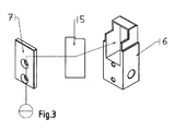
- the in FIG. 4 Example illustrated magnet 5 with a geometrically specially machined housing 6,7 coated ferromagnetic material.
- This material is provided with very specific physical properties. Essentially, these are magnetically highly conductive materials that are used in the purest form or as alloys.
- the special physical properties of the material are a very high magnetic saturation induction ⁇ 2 Tesla, a very low coercivity and remanence and a high permeability.
- the sheath may in this case have a magnetic saturation greater than 1.2 Tesla and preferably in the range between 1.3 and 2.5 Tesla.
- the sheath 6, 7 can consist of pure iron or of an alloy with pure iron.
- This body 17 is together with the associated magnetic field guide in FIG. 5 shown and worked so that it represents on the entrance side either by a chamfer or a rounding the transition from the upstanding wall in the horizontal wall - directly on the pole of the magnet - as a closed body.
- the body In the region 9, from which the permanent magnetic field is reversed from plus to minus, the body is closed on all sides and executed with such high mass - material - that the magnetic field in the region of the pole is approximately neutral ⁇ 10 mT.
- FIG. 4 shown pole face 14,15 and their geometric design. This relates both to the magnetic field guiding body 17, cf. FIG. 5 , as well as in FIG. 4 bar magnet shown.
- the magnet is provided with an offset on the pole face.
- This offset regardless of the shape of the pole face of the magnet - round or polygonal - is to be designed in the height of the offset so that the new pole face in the offset has the same polarity as the unprocessed surface.
- the offset step with a corresponding radius 15 or other geometries, cf. Figure 6 - 6d , to design.
- the magnetic body according to the invention may have different geometries, e.g. be rod-shaped, disc-shaped or polygonal.
- the cross section may be formed, for example, rectangular, triangular or trapezoidal.
- the continuous end face is formed flat.
- the first pole face 14 includes a step having an upper step surface, a lower step surface, and a step transition surface disposed between upper and lower step surfaces, the upper step surface being formed by the free pole face.
- step transition surface and lower step surface can be formed so that it is angular in cross-section considered. Also, the transition between lower step surface and lateral surface can be bevelled or rounded at least on the side of the lower step surface 19, 20 opposite the transition surface.
- the transition between lower step surface 21 and lateral surface is concave, at least on the side of the lower step surface opposite the transition surface.
- the transition between lower step surface 22 and lateral surface is convex at least on the side of the lower step surface opposite the transition surface.
- the transition between the lower step surface 23 and lateral surface may be at least on the side opposite the transition surface of the lower step surface, bevelled or rounded or both.
- the Poldeckel Design of the housing in the region of the offset is to be designed so that the thickness of the wall of the lid depending on the permanent magnetic field magnetization strength - the remaining magnetic field remaining field - and the attraction - adhesive force of the magnetic field guide housing - volume housing mass between two oppositely acting functional units 3.4 a balance between the attractive force of the housing shell in the area of the effective area and the residual repulsive force of the residual magnetic field - over the in Fig. 5 shown lid surface - as a unipolar operating principle - prevails.
- the side walls of the magnetic field guide body are to be dimensioned so that a corresponding residual magnetic field is formed in the same polarity as the active surface. This wall thickness is to be carried out in the region of the reversal point of the magnetic field 9. Within the side wall a notch of the surface of the side wall is notched in the direction of rotation. This additionally supports the preferred direction.
- the magnetic field guide In the area of the pole reversal of the bar magnet 9, the magnetic field guide, as in FIG. 5 shown, completely closed in a carcass.
- the wall thickness becomes such increases that creates a magnetically neutral field ⁇ 10 mT on the outer surface of the body.
- the effective magnetic field is neutral.
- the bottom of the housing 6 is dimensioned so strong that the magnetic field is neutralized and all necessary for mounting and mounting of the magnet system holes or other types of fastening are included and the actual function is not affected.
- the closure lid 7 is made of the same material as the magnetic field guide body 6.
- the lid closes in the region of the reversal point 9 of the magnetic field.
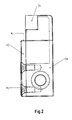
- FIG. 2 are the size and the mounting of the cap shown.
- the functional unit generates a monopolar magnetic field, which can be precisely adjusted in its effective direction and field strength. Due to the special design of the magnetic field guide body, the original magnetic field 18 is retained only in the free, open pole surface 16 and thus in a precisely definable effective direction. The remaining magnetic field is diffracted and guided within the wall of the magnetic field guiding body 6, 7, so that the stability of the entire magnetic field is not changed or weakened. This is a prerequisite for the function of the magnet and the magnetic field.
- the partial area without sheathing can amount to between 4% and 40% of the surface of the magnetic body. According to the invention, it is possible to make the sheath 6 thinner in the region of the first pole face 14 than in the remaining area.
- the sheath 6 can also be designed such that it extends beyond the second pole face and is designed as a fastening device for the permanent magnet.
- the first pole face of the magnetic body has, seen in cross section, a profile deviating from a straight line, and the sheath 6 partially covering the first pole face 14 and the free pole face form a continuous end face, wherein the face can be flat.
- the sheath 6 partially covers the first pole face 14, leaving a free pole face which is not covered by the sheath.
- the sheath 6 can be made thinner in the region of the first pole face 14 than in the remaining area.
- the first pole face 14 may include a step having an upper step surface, a lower step surface, and a step transition surface disposed between upper and lower step surfaces, and the upper step surface may be formed by the free pole surface.
- the transition between step transition surface and lower step surface in cross section can be considered angular.
- the transition between the free pole face and the step transition face can be formed at an angle, in particular at right angles.
- Vortex fields In the area of the housing bottom, ie in the closed housing 6, 7, depending on the magnetization strength, the magnetic field guide or wall thickness is to be made so large that the magnetic field is completely trapped in the material and to the outside magnetically neutral. This ensures that no disturbing alternating fields or compressed vortex fields arise, which can influence the function of the magnetic bearing.
- this design allows all important construction materials to be used in the static design of the bearing without the risk of being affected by the permanent magnetic field.
Landscapes
- Engineering & Computer Science (AREA)
- General Engineering & Computer Science (AREA)
- Mechanical Engineering (AREA)
- Physics & Mathematics (AREA)
- Electromagnetism (AREA)
- Power Engineering (AREA)
- Magnetic Bearings And Hydrostatic Bearings (AREA)
Claims (15)
- Aimant permanent avec un corps d'aimant en un matériau magnétique permanent qui présente un pôle nord et un pôle sud, le corps d'aimant présentant une première et une seconde surface de pôle à des extrémités opposées avec une surface d'enveloppe entre deux et avec un enrobage (6, 7) en un matériau ferromagnétique qui enferme le corps d'aimant à l'exception d'une zone partielle dans la zone de la première surface de pôle,
l'enrobage (6) recouvrant partiellement la première surface de pôle (14) si bien qu'il reste une surface de pôle libre qui n'est pas recouverte par l'enrobage,
caractérisé en ce
qu'en particulier l'enrobage (6) est plus mince dans la zone de la première surface de pôle (14) que dans le reste de la zone,
que la première surface de pôle du corps d'aimant présente un profil qui diffère d'une droite, ceci étant vu en section transversale, et
que l'enrobage (6) qui recouvre partiellement la première surface de pôle (14) et la surface de pôle libre forment une face frontale continue, en particulier plane. - Aimant permanent selon la revendication 1,
caractérisé en ce
que l'enrobage présente une saturation magnétique supérieure à 1,2 Tesla et de préférence de l'ordre entre 1,3 et 2,5 Tesla. - Aimant permanent selon la revendication 1 ou 2,
caractérisé en ce
que l'enrobage (6, 7) est constitué en fer pur ou en un alliage avec du fer pur. - Aimant permanent selon l'une des revendications précédentes,
caractérisé en ce
que la zone partielle sans enrobage fait entre 4% et 40% de la surface du corps de l'aimant. - Aimant permanent selon l'une des revendications précédentes,
caractérisé en ce
que le corps de l'aimant est en forme de barre. - Aimant permanent selon l'une des revendications précédentes 1 à 4,
caractérisé en ce
que le corps de l'aimant est en forme de disque ou est polygonal. - Aimant permanent selon l'une des revendications précédentes,
caractérisé en ce- que la première surface de pôle (14) présente un étage avec une surface d'étage supérieure, une surface d'étage inférieure et une surface de transition d'étage placée entre la surface d'étage supérieure et la surface d'étage inférieure et- que la surface d'étage supérieure est formée par la surface de pôle libre. - Aimant permanent selon la revendication 7,
caractérisé en ce
que la transition entre la surface de transition d'étage et la surface d'étage inférieure est angulaire, ceci étant observé en section transversale. - Aimant permanent selon la revendication 7 ou 8,
caractérisé en ce
que la transition entre la surface de pôle libre et la surface de transition d'étage est angulaire, en particulier à angles droits, ceci étant observé en section transversale. - Aimant permanent selon l'une des revendications précédentes,
caractérisé en ce
que le corps d'aimant présente une section transversale rectangulaire. - Aimant permanent selon l'une des revendications précédentes,
caractérisé en ce
que le corps d'aimant présente une section transversale triangulaire ou trapézoïdale. - Aimant permanent selon l'une des revendications précédentes,
caractérisé en ce
que l'enrobage (6) s'étend au-delà de la seconde surface de pôle et est configuré comme un dispositif de fixation pour l'aimant permanent. - Aimant permanent selon l'une des revendications précédentes,
caractérisé en ce
que la transition entre la surface d'étage inférieure (23) et la surface d'enveloppe est chanfreinée au moins sur le côté de la surface d'étage inférieure qui est en face de la surface de transition ou est arrondie ou les deux ou est concave ou convexe. - Palier de rotation avec une première multitude d'aimants permanents selon l'une des revendications précédentes qui sont placés sur un anneau intérieur (2) dans l'orientation radiale avec la surface de pôle libre vers l'extérieur,● une seconde multitude d'aimants permanents selon l'une des revendications précédentes qui sont placés sur un anneau extérieur (1) dans l'orientation radiale avec la surface de pôle libre vers l'intérieur,● l'anneau intérieur et l'anneau extérieur (1, 2) étant placés concentriques l'un par rapport à l'autre,● les aimants permanents étant placés sur l'anneau intérieur (2) de telle manière que les surfaces de pôle libres de deux aimants permanents directement voisins ne sont pas directement en face l'une de l'autre,● les aimants permanents étant placés sur l'anneau extérieur (1) de telle manière que les surfaces de pôle libres de deux aimants permanents directement voisins ne sont pas directement en face l'une de l'autre et● un aimant permanent dans l'anneau intérieur qui est directement en face d'un aimant permanent dans l'anneau extérieur, est symétrique par points à l'aimant permanent dans l'anneau extérieur pour ce qui est de la disposition de la surface de pôle libre et de la première surface de pôle enrobée● cependant que en particulier les aimants permanents sont placés dans l'angle aigu par rapport au sens radial de l'anneau intérieur et de l'anneau extérieur.
- Palier de rotation selon la revendication 14,
caractérisé en ce
que les différents aimants permanents sont placés sur l'anneau intérieur et sur l'anneau extérieur dans le sens de la circonférence à égale distance l'un par rapport à l'autre, cependant que en particulier le nombre des aimants permanents dans l'anneau intérieur est égal ou inégal au nombre des aimants permanents dans l'anneau extérieur.
Applications Claiming Priority (2)
| Application Number | Priority Date | Filing Date | Title |
|---|---|---|---|
| DE102008009734A DE102008009734B4 (de) | 2008-02-19 | 2008-02-19 | Permanentmagnet und Drehlager mit solchen Permanentmagneten |
| PCT/EP2009/051520 WO2009103633A1 (fr) | 2008-02-19 | 2009-02-11 | Aimant permanent et palier de rotation pourvu d’un tel aimant permanent |
Publications (2)
| Publication Number | Publication Date |
|---|---|
| EP2247865A1 EP2247865A1 (fr) | 2010-11-10 |
| EP2247865B1 true EP2247865B1 (fr) | 2013-06-26 |
Family
ID=40491066
Family Applications (1)
| Application Number | Title | Priority Date | Filing Date |
|---|---|---|---|
| EP09713207.0A Not-in-force EP2247865B1 (fr) | 2008-02-19 | 2009-02-11 | Aimant permanent et palier de rotation pourvu d'un tel aimant permanent |
Country Status (12)
| Country | Link |
|---|---|
| US (1) | US20110001380A1 (fr) |
| EP (1) | EP2247865B1 (fr) |
| JP (1) | JP2011517059A (fr) |
| KR (1) | KR20100116668A (fr) |
| CN (1) | CN101952612A (fr) |
| AU (1) | AU2009216832A1 (fr) |
| BR (1) | BRPI0907836A2 (fr) |
| CA (1) | CA2715978A1 (fr) |
| DE (1) | DE102008009734B4 (fr) |
| MX (1) | MX2010009076A (fr) |
| WO (1) | WO2009103633A1 (fr) |
| ZA (1) | ZA201005588B (fr) |
Families Citing this family (2)
| Publication number | Priority date | Publication date | Assignee | Title |
|---|---|---|---|---|
| DE102012216450A1 (de) * | 2012-09-14 | 2014-03-20 | Pfeiffer Vacuum Gmbh | Verfahren zum Zentrieren einer Vakuumpumpe oder einer Rotationseinheit für eine Vakuumpumpe |
| US20230275444A1 (en) * | 2022-02-25 | 2023-08-31 | Milwaukee Electric Tool Corporation | Magnet coupling assembly |
Family Cites Families (17)
| Publication number | Priority date | Publication date | Assignee | Title |
|---|---|---|---|---|
| US2568479A (en) * | 1948-08-09 | 1951-09-18 | Scott Atwater Mfg Company | Magneto structure and method of making the same |
| US4538130A (en) * | 1984-04-23 | 1985-08-27 | Field Effects, Inc. | Tunable segmented ring magnet and method of manufacture |
| JPH027855A (ja) * | 1988-06-23 | 1990-01-11 | Seiko Epson Corp | 発電機 |
| US4992733A (en) * | 1989-11-17 | 1991-02-12 | Visi-Trak Corporation | Position sensing transducer having a circular magnet with an integral flux distorting member and two magnetic field sensors |
| WO1991012648A1 (fr) * | 1990-02-13 | 1991-08-22 | Hitachi Metals, Ltd. | Moteur lineaire a courant continu |
| EP0523002B1 (fr) * | 1991-07-11 | 1996-02-28 | LAUBE, Hans-Jürgen | Aimant composé comprenant plusieurs aimants individuels et palier magnétique permanent avec un aimant composé comprenant plusieurs aimants individuels |
| EP0535901A3 (en) * | 1991-09-30 | 1993-11-03 | Kawasaki Steel Co | Lateral orientation anisotropic magnet |
| JP3340259B2 (ja) * | 1994-03-23 | 2002-11-05 | 株式会社日立製作所 | 自動車用オルタネータ |
| JP3675010B2 (ja) * | 1995-02-17 | 2005-07-27 | セイコーエプソン株式会社 | 超電導軸受装置 |
| KR100367968B1 (ko) * | 1999-08-03 | 2003-01-14 | 이문호 | 자기장 균일화 공간구조 |
| DE29922073U1 (de) * | 1999-12-15 | 2000-03-23 | Merlaku, Kastriot, 84347 Pfarrkirchen | Berührungslose Magnet-Lager |
| US20030052564A1 (en) * | 2001-07-09 | 2003-03-20 | Doris Wilsdorf | Bipolar machines-a new class of homopolar motor/generator |
| US6813115B2 (en) * | 2002-04-18 | 2004-11-02 | Seagate Technology Llc | Perpendicular magnetic recording head with improved write field gradient |
| ITSV20030011A1 (it) * | 2003-03-31 | 2004-10-01 | Esaote Spa | Struttura magnetica per macchine di acquisiszione di |
| US20070018764A1 (en) * | 2005-07-19 | 2007-01-25 | Analisi Tecnologica Innovadora Per A Processos | Device and method for separating magnetic particles |
| JP2007040316A (ja) * | 2005-07-29 | 2007-02-15 | Smc Corp | 環状磁石およびそれを用いた流体圧シリンダ |
| DE202005020288U1 (de) * | 2005-12-23 | 2007-05-03 | H. Wernert & Co. Ohg | Permanentmagnetische berührungsfreie Radialdrehkupplung |
-
2008
- 2008-02-19 DE DE102008009734A patent/DE102008009734B4/de not_active Expired - Fee Related
-
2009
- 2009-02-11 US US12/918,348 patent/US20110001380A1/en not_active Abandoned
- 2009-02-11 JP JP2010547147A patent/JP2011517059A/ja active Pending
- 2009-02-11 KR KR1020107020804A patent/KR20100116668A/ko not_active Withdrawn
- 2009-02-11 CN CN2009801056961A patent/CN101952612A/zh active Pending
- 2009-02-11 AU AU2009216832A patent/AU2009216832A1/en not_active Abandoned
- 2009-02-11 CA CA2715978A patent/CA2715978A1/fr not_active Abandoned
- 2009-02-11 MX MX2010009076A patent/MX2010009076A/es not_active Application Discontinuation
- 2009-02-11 WO PCT/EP2009/051520 patent/WO2009103633A1/fr not_active Ceased
- 2009-02-11 EP EP09713207.0A patent/EP2247865B1/fr not_active Not-in-force
- 2009-02-11 BR BRPI0907836 patent/BRPI0907836A2/pt not_active Application Discontinuation
-
2010
- 2010-08-05 ZA ZA2010/05588A patent/ZA201005588B/en unknown
Also Published As
| Publication number | Publication date |
|---|---|
| US20110001380A1 (en) | 2011-01-06 |
| EP2247865A1 (fr) | 2010-11-10 |
| AU2009216832A1 (en) | 2009-08-27 |
| BRPI0907836A2 (pt) | 2019-12-10 |
| MX2010009076A (es) | 2010-12-14 |
| WO2009103633A1 (fr) | 2009-08-27 |
| ZA201005588B (en) | 2011-07-27 |
| AU2009216832A2 (en) | 2010-09-09 |
| CN101952612A (zh) | 2011-01-19 |
| DE102008009734A1 (de) | 2009-09-24 |
| JP2011517059A (ja) | 2011-05-26 |
| KR20100116668A (ko) | 2010-11-01 |
| DE102008009734B4 (de) | 2010-09-16 |
| CA2715978A1 (fr) | 2009-08-27 |
Similar Documents
| Publication | Publication Date | Title |
|---|---|---|
| DE102018100390A1 (de) | Magnetorheologische Bremseinrichtung | |
| DE69023887T2 (de) | Einphasiger elektromagnetischer betätiger mit geringem raumbedarf. | |
| EP2150717B2 (fr) | Dispositif de transmission de couple magnétorhéologique, son procédé d'utilisation, et procédé de transmission de couple magnétorhéologique associé | |
| EP2989254B1 (fr) | Dispositif d'appui coulissant pour ouvrage et procédé de dimensionnement | |
| WO2019219881A1 (fr) | Accouplement rotatif radial à aimants permanents | |
| DE2821973A1 (de) | Magnetische drehmomentkupplung | |
| DE3047606C2 (de) | Lageranordnung für einen länglichen, um seine Längsachse drehbaren Drehkörper | |
| DE2208034A1 (de) | Selbsteinmittende Lagerung unter Verwendung von Permanentmagneten | |
| EP4607055A2 (fr) | Appareil comprenant un dispositif de freinage magnétorhéologique et procédé | |
| EP2247865B1 (fr) | Aimant permanent et palier de rotation pourvu d'un tel aimant permanent | |
| EP1419510B1 (fr) | Objet magnetique a aimantation permanente et procede de reglage de la direction et de la position d'un vecteur magnetique | |
| EP3484024B1 (fr) | Actionneur | |
| DE102021209129A1 (de) | Magnetisches getriebe | |
| DE102007040018A1 (de) | Permanentmagnetischer Motor mit magnetischem Axiallager | |
| DE1930847A1 (de) | Vorrichtung zum Antrieb einer Spindel | |
| DE202019103225U1 (de) | Drehmomentoptimierter mehrpoliger Rotor für einen Elektromotor | |
| DE60209992T2 (de) | Linearführung und Walzbacken zu ihrer Herstellung | |
| DE3229907A1 (de) | Elektromagnetische anzeigevorrichtung mit einem in definierte positionen bringbaren rotor | |
| EP1867956A1 (fr) | Agrandissement de la distance active pour capteurs magnétiques à l'aide d'un champ de support | |
| DE2363711A1 (de) | Elektromagnetische antriebsvorrichtung, vorzugsweise instrumenten-messwerk | |
| EP1028262A1 (fr) | Dispositif de palier electromagnétique | |
| EP4124770B1 (fr) | Palier de butée et disque polaire pour palier de butée | |
| DE102017103332A1 (de) | Magnetlager und Verfahren zum Betrieb eines Magnetlagers | |
| DE202017007061U1 (de) | Gehäuse für einen Elektromotor | |
| DE2821089C2 (de) | Vielpolige Magnetkupplung |
Legal Events
| Date | Code | Title | Description |
|---|---|---|---|
| PUAI | Public reference made under article 153(3) epc to a published international application that has entered the european phase |
Free format text: ORIGINAL CODE: 0009012 |
|
| 17P | Request for examination filed |
Effective date: 20100830 |
|
| AK | Designated contracting states |
Kind code of ref document: A1 Designated state(s): AT BE BG CH CY CZ DE DK EE ES FI FR GB GR HR HU IE IS IT LI LT LU LV MC MK MT NL NO PL PT RO SE SI SK TR |
|
| AX | Request for extension of the european patent |
Extension state: AL BA RS |
|
| DAX | Request for extension of the european patent (deleted) | ||
| 17Q | First examination report despatched |
Effective date: 20111128 |
|
| REG | Reference to a national code |
Ref country code: DE Ref legal event code: R079 Ref document number: 502009007425 Country of ref document: DE Free format text: PREVIOUS MAIN CLASS: F16C0039060000 Ipc: F16C0032040000 |
|
| GRAP | Despatch of communication of intention to grant a patent |
Free format text: ORIGINAL CODE: EPIDOSNIGR1 |
|
| RIC1 | Information provided on ipc code assigned before grant |
Ipc: F16C 32/04 20060101AFI20121218BHEP Ipc: H01F 7/02 20060101ALI20121218BHEP |
|
| GRAS | Grant fee paid |
Free format text: ORIGINAL CODE: EPIDOSNIGR3 |
|
| GRAA | (expected) grant |
Free format text: ORIGINAL CODE: 0009210 |
|
| AK | Designated contracting states |
Kind code of ref document: B1 Designated state(s): AT BE BG CH CY CZ DE DK EE ES FI FR GB GR HR HU IE IS IT LI LT LU LV MC MK MT NL NO PL PT RO SE SI SK TR |
|
| REG | Reference to a national code |
Ref country code: GB Ref legal event code: FG4D Free format text: NOT ENGLISH |
|
| REG | Reference to a national code |
Ref country code: CH Ref legal event code: EP |
|
| REG | Reference to a national code |
Ref country code: AT Ref legal event code: REF Ref document number: 618821 Country of ref document: AT Kind code of ref document: T Effective date: 20130715 |
|
| REG | Reference to a national code |
Ref country code: IE Ref legal event code: FG4D Free format text: LANGUAGE OF EP DOCUMENT: GERMAN |
|
| REG | Reference to a national code |
Ref country code: DE Ref legal event code: R096 Ref document number: 502009007425 Country of ref document: DE Effective date: 20130822 |
|
| REG | Reference to a national code |
Ref country code: CH Ref legal event code: NV Representative=s name: KAMINSKI HARMANN PATENTANWAELTE AG, LI |
|
| PG25 | Lapsed in a contracting state [announced via postgrant information from national office to epo] |
Ref country code: SE Free format text: LAPSE BECAUSE OF FAILURE TO SUBMIT A TRANSLATION OF THE DESCRIPTION OR TO PAY THE FEE WITHIN THE PRESCRIBED TIME-LIMIT Effective date: 20130626 Ref country code: SI Free format text: LAPSE BECAUSE OF FAILURE TO SUBMIT A TRANSLATION OF THE DESCRIPTION OR TO PAY THE FEE WITHIN THE PRESCRIBED TIME-LIMIT Effective date: 20130626 Ref country code: NO Free format text: LAPSE BECAUSE OF FAILURE TO SUBMIT A TRANSLATION OF THE DESCRIPTION OR TO PAY THE FEE WITHIN THE PRESCRIBED TIME-LIMIT Effective date: 20130926 Ref country code: LT Free format text: LAPSE BECAUSE OF FAILURE TO SUBMIT A TRANSLATION OF THE DESCRIPTION OR TO PAY THE FEE WITHIN THE PRESCRIBED TIME-LIMIT Effective date: 20130626 Ref country code: GR Free format text: LAPSE BECAUSE OF FAILURE TO SUBMIT A TRANSLATION OF THE DESCRIPTION OR TO PAY THE FEE WITHIN THE PRESCRIBED TIME-LIMIT Effective date: 20130927 Ref country code: FI Free format text: LAPSE BECAUSE OF FAILURE TO SUBMIT A TRANSLATION OF THE DESCRIPTION OR TO PAY THE FEE WITHIN THE PRESCRIBED TIME-LIMIT Effective date: 20130626 |
|
| REG | Reference to a national code |
Ref country code: LT Ref legal event code: MG4D |
|
| PG25 | Lapsed in a contracting state [announced via postgrant information from national office to epo] |
Ref country code: HR Free format text: LAPSE BECAUSE OF FAILURE TO SUBMIT A TRANSLATION OF THE DESCRIPTION OR TO PAY THE FEE WITHIN THE PRESCRIBED TIME-LIMIT Effective date: 20130626 Ref country code: BG Free format text: LAPSE BECAUSE OF FAILURE TO SUBMIT A TRANSLATION OF THE DESCRIPTION OR TO PAY THE FEE WITHIN THE PRESCRIBED TIME-LIMIT Effective date: 20130926 |
|
| REG | Reference to a national code |
Ref country code: NL Ref legal event code: VDEP Effective date: 20130626 |
|
| PG25 | Lapsed in a contracting state [announced via postgrant information from national office to epo] |
Ref country code: LV Free format text: LAPSE BECAUSE OF FAILURE TO SUBMIT A TRANSLATION OF THE DESCRIPTION OR TO PAY THE FEE WITHIN THE PRESCRIBED TIME-LIMIT Effective date: 20130626 |
|
| PG25 | Lapsed in a contracting state [announced via postgrant information from national office to epo] |
Ref country code: IS Free format text: LAPSE BECAUSE OF FAILURE TO SUBMIT A TRANSLATION OF THE DESCRIPTION OR TO PAY THE FEE WITHIN THE PRESCRIBED TIME-LIMIT Effective date: 20131026 Ref country code: PT Free format text: LAPSE BECAUSE OF FAILURE TO SUBMIT A TRANSLATION OF THE DESCRIPTION OR TO PAY THE FEE WITHIN THE PRESCRIBED TIME-LIMIT Effective date: 20131028 Ref country code: CZ Free format text: LAPSE BECAUSE OF FAILURE TO SUBMIT A TRANSLATION OF THE DESCRIPTION OR TO PAY THE FEE WITHIN THE PRESCRIBED TIME-LIMIT Effective date: 20130626 Ref country code: EE Free format text: LAPSE BECAUSE OF FAILURE TO SUBMIT A TRANSLATION OF THE DESCRIPTION OR TO PAY THE FEE WITHIN THE PRESCRIBED TIME-LIMIT Effective date: 20130626 Ref country code: SK Free format text: LAPSE BECAUSE OF FAILURE TO SUBMIT A TRANSLATION OF THE DESCRIPTION OR TO PAY THE FEE WITHIN THE PRESCRIBED TIME-LIMIT Effective date: 20130626 Ref country code: CY Free format text: LAPSE BECAUSE OF FAILURE TO SUBMIT A TRANSLATION OF THE DESCRIPTION OR TO PAY THE FEE WITHIN THE PRESCRIBED TIME-LIMIT Effective date: 20130911 |
|
| PG25 | Lapsed in a contracting state [announced via postgrant information from national office to epo] |
Ref country code: NL Free format text: LAPSE BECAUSE OF FAILURE TO SUBMIT A TRANSLATION OF THE DESCRIPTION OR TO PAY THE FEE WITHIN THE PRESCRIBED TIME-LIMIT Effective date: 20130626 Ref country code: ES Free format text: LAPSE BECAUSE OF FAILURE TO SUBMIT A TRANSLATION OF THE DESCRIPTION OR TO PAY THE FEE WITHIN THE PRESCRIBED TIME-LIMIT Effective date: 20131007 Ref country code: RO Free format text: LAPSE BECAUSE OF FAILURE TO SUBMIT A TRANSLATION OF THE DESCRIPTION OR TO PAY THE FEE WITHIN THE PRESCRIBED TIME-LIMIT Effective date: 20130626 Ref country code: PL Free format text: LAPSE BECAUSE OF FAILURE TO SUBMIT A TRANSLATION OF THE DESCRIPTION OR TO PAY THE FEE WITHIN THE PRESCRIBED TIME-LIMIT Effective date: 20130626 |
|
| PG25 | Lapsed in a contracting state [announced via postgrant information from national office to epo] |
Ref country code: CY Free format text: LAPSE BECAUSE OF FAILURE TO SUBMIT A TRANSLATION OF THE DESCRIPTION OR TO PAY THE FEE WITHIN THE PRESCRIBED TIME-LIMIT Effective date: 20130626 |
|
| PG25 | Lapsed in a contracting state [announced via postgrant information from national office to epo] |
Ref country code: DK Free format text: LAPSE BECAUSE OF FAILURE TO SUBMIT A TRANSLATION OF THE DESCRIPTION OR TO PAY THE FEE WITHIN THE PRESCRIBED TIME-LIMIT Effective date: 20130626 |
|
| PLBE | No opposition filed within time limit |
Free format text: ORIGINAL CODE: 0009261 |
|
| STAA | Information on the status of an ep patent application or granted ep patent |
Free format text: STATUS: NO OPPOSITION FILED WITHIN TIME LIMIT |
|
| PG25 | Lapsed in a contracting state [announced via postgrant information from national office to epo] |
Ref country code: IT Free format text: LAPSE BECAUSE OF FAILURE TO SUBMIT A TRANSLATION OF THE DESCRIPTION OR TO PAY THE FEE WITHIN THE PRESCRIBED TIME-LIMIT Effective date: 20130626 |
|
| 26N | No opposition filed |
Effective date: 20140327 |
|
| REG | Reference to a national code |
Ref country code: DE Ref legal event code: R097 Ref document number: 502009007425 Country of ref document: DE Effective date: 20140327 |
|
| BERE | Be: lapsed |
Owner name: MAD, MAGNETIC DRIVE AG Effective date: 20140228 |
|
| PG25 | Lapsed in a contracting state [announced via postgrant information from national office to epo] |
Ref country code: MC Free format text: LAPSE BECAUSE OF FAILURE TO SUBMIT A TRANSLATION OF THE DESCRIPTION OR TO PAY THE FEE WITHIN THE PRESCRIBED TIME-LIMIT Effective date: 20130626 Ref country code: LU Free format text: LAPSE BECAUSE OF FAILURE TO SUBMIT A TRANSLATION OF THE DESCRIPTION OR TO PAY THE FEE WITHIN THE PRESCRIBED TIME-LIMIT Effective date: 20140211 |
|
| REG | Reference to a national code |
Ref country code: IE Ref legal event code: MM4A |
|
| PG25 | Lapsed in a contracting state [announced via postgrant information from national office to epo] |
Ref country code: BE Free format text: LAPSE BECAUSE OF NON-PAYMENT OF DUE FEES Effective date: 20140228 Ref country code: IE Free format text: LAPSE BECAUSE OF NON-PAYMENT OF DUE FEES Effective date: 20140211 |
|
| REG | Reference to a national code |
Ref country code: FR Ref legal event code: PLFP Year of fee payment: 8 |
|
| PG25 | Lapsed in a contracting state [announced via postgrant information from national office to epo] |
Ref country code: MT Free format text: LAPSE BECAUSE OF FAILURE TO SUBMIT A TRANSLATION OF THE DESCRIPTION OR TO PAY THE FEE WITHIN THE PRESCRIBED TIME-LIMIT Effective date: 20130626 |
|
| PG25 | Lapsed in a contracting state [announced via postgrant information from national office to epo] |
Ref country code: TR Free format text: LAPSE BECAUSE OF FAILURE TO SUBMIT A TRANSLATION OF THE DESCRIPTION OR TO PAY THE FEE WITHIN THE PRESCRIBED TIME-LIMIT Effective date: 20130626 Ref country code: HU Free format text: LAPSE BECAUSE OF FAILURE TO SUBMIT A TRANSLATION OF THE DESCRIPTION OR TO PAY THE FEE WITHIN THE PRESCRIBED TIME-LIMIT; INVALID AB INITIO Effective date: 20090211 |
|
| REG | Reference to a national code |
Ref country code: FR Ref legal event code: PLFP Year of fee payment: 9 |
|
| REG | Reference to a national code |
Ref country code: FR Ref legal event code: PLFP Year of fee payment: 10 |
|
| PG25 | Lapsed in a contracting state [announced via postgrant information from national office to epo] |
Ref country code: MK Free format text: LAPSE BECAUSE OF FAILURE TO SUBMIT A TRANSLATION OF THE DESCRIPTION OR TO PAY THE FEE WITHIN THE PRESCRIBED TIME-LIMIT Effective date: 20130626 |
|
| PGFP | Annual fee paid to national office [announced via postgrant information from national office to epo] |
Ref country code: DE Payment date: 20200303 Year of fee payment: 12 Ref country code: GB Payment date: 20200219 Year of fee payment: 12 Ref country code: AT Payment date: 20200219 Year of fee payment: 12 |
|
| PGFP | Annual fee paid to national office [announced via postgrant information from national office to epo] |
Ref country code: CH Payment date: 20200220 Year of fee payment: 12 |
|
| PGFP | Annual fee paid to national office [announced via postgrant information from national office to epo] |
Ref country code: FR Payment date: 20200219 Year of fee payment: 12 |
|
| REG | Reference to a national code |
Ref country code: DE Ref legal event code: R119 Ref document number: 502009007425 Country of ref document: DE |
|
| REG | Reference to a national code |
Ref country code: AT Ref legal event code: MM01 Ref document number: 618821 Country of ref document: AT Kind code of ref document: T Effective date: 20210211 |
|
| GBPC | Gb: european patent ceased through non-payment of renewal fee |
Effective date: 20210211 |
|
| PG25 | Lapsed in a contracting state [announced via postgrant information from national office to epo] |
Ref country code: CH Free format text: LAPSE BECAUSE OF NON-PAYMENT OF DUE FEES Effective date: 20210228 Ref country code: AT Free format text: LAPSE BECAUSE OF NON-PAYMENT OF DUE FEES Effective date: 20210211 Ref country code: LI Free format text: LAPSE BECAUSE OF NON-PAYMENT OF DUE FEES Effective date: 20210228 |
|
| PG25 | Lapsed in a contracting state [announced via postgrant information from national office to epo] |
Ref country code: DE Free format text: LAPSE BECAUSE OF NON-PAYMENT OF DUE FEES Effective date: 20210901 Ref country code: GB Free format text: LAPSE BECAUSE OF NON-PAYMENT OF DUE FEES Effective date: 20210211 Ref country code: FR Free format text: LAPSE BECAUSE OF NON-PAYMENT OF DUE FEES Effective date: 20210228 |