EP2247921B1 - Bestimmung von koordinaten eines ziels in bezug auf vermessungsinstrumente mit einer kamera - Google Patents
Bestimmung von koordinaten eines ziels in bezug auf vermessungsinstrumente mit einer kamera Download PDFInfo
- Publication number
- EP2247921B1 EP2247921B1 EP08707675.8A EP08707675A EP2247921B1 EP 2247921 B1 EP2247921 B1 EP 2247921B1 EP 08707675 A EP08707675 A EP 08707675A EP 2247921 B1 EP2247921 B1 EP 2247921B1
- Authority
- EP
- European Patent Office
- Prior art keywords
- image
- camera
- object point
- target
- surveying instrument
- Prior art date
- Legal status (The legal status is an assumption and is not a legal conclusion. Google has not performed a legal analysis and makes no representation as to the accuracy of the status listed.)
- Active
Links
Images



Classifications
-
- G—PHYSICS
- G01—MEASURING; TESTING
- G01C—MEASURING DISTANCES, LEVELS OR BEARINGS; SURVEYING; NAVIGATION; GYROSCOPIC INSTRUMENTS; PHOTOGRAMMETRY OR VIDEOGRAMMETRY
- G01C11/00—Photogrammetry or videogrammetry, e.g. stereogrammetry; Photographic surveying
- G01C11/04—Interpretation of pictures
- G01C11/06—Interpretation of pictures by comparison of two or more pictures of the same area
-
- G—PHYSICS
- G01—MEASURING; TESTING
- G01C—MEASURING DISTANCES, LEVELS OR BEARINGS; SURVEYING; NAVIGATION; GYROSCOPIC INSTRUMENTS; PHOTOGRAMMETRY OR VIDEOGRAMMETRY
- G01C1/00—Measuring angles
- G01C1/02—Theodolites
- G01C1/04—Theodolites combined with cameras
-
- G—PHYSICS
- G01—MEASURING; TESTING
- G01C—MEASURING DISTANCES, LEVELS OR BEARINGS; SURVEYING; NAVIGATION; GYROSCOPIC INSTRUMENTS; PHOTOGRAMMETRY OR VIDEOGRAMMETRY
- G01C15/00—Surveying instruments or accessories not provided for in groups G01C1/00 - G01C13/00
Definitions
- the present invention relates to surveying instruments, such as total stations. More particularly, the present invention relates to a method for determining coordinates of a target in relation to a surveying instrument having a camera for capturing a field of view and an identified target point within the field of view.
- a camera in a geodetic instrument may provide for improved user convenience and new functions.
- a view such as an image or a video feed provided by the camera and shown on a display of the instrument may be used for assisting target selection and for providing the user with an overview of potential points of interest.
- the display image may have an active overlay of information.
- Various information may be given together with the captured image to facilitate instrument usage.
- Surveying instruments of this kind i.e. which includes a camera, are sometimes referred to as video-theodolites.
- Document DE102007030784 A1 discloses a surveying instrument and a method for determining coordinates of a target.
- the surveying instrument includes a camera, eccentric to a rotation center of the surveying instrument, that can capture an image of the target from two different positions by rotating the surveying instrument around the rotation center.
- the present invention provides a method for determining, in relation to a surveying instrument, target coordinates of a point of interest, or target, identified in two images captured by a camera in the surveying instrument.
- the present invention provides a method for determining coordinates of a target in relation to a surveying instrument according to claim 1.
- the present invention makes use of an understanding that the coordinates of the point of interest from the surveying instrument can be determined by using the eccentricity of a camera in the surveying instrument for capturing two images from the camera in two known camera positions and orientations with intermediate rotation of the surveying instrument and identification of an object point and the coordinates thereof in the two images together with camera calibration data.
- target coordinates with respect to the rotational center of the instrument have been determined, distance from the rotation center to the target can be determined.
- target coordinates may be used for other purposes than determining distance. For instance, it may be useful to measure coordinates of a ground mark very accurately for surveying instrument stationing.
- the present invention also provides a surveying instrument according to claim 15.
- the present invention can be implemented in a computer program that, when executed, performs the inventive method in a surveying instrument.
- the computer program may, for example, be downloaded into a surveying instrument as an upgrade.
- the inventive method can be implemented for a surveying instrument using software, hardware or firmware, or a combination thereof, as desired in view of the particular circumstances.
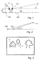
- FIG. 1 illustrates schematically a situation where an object point relating to a target P is identified in an image captured by a camera in a surveying instrument.
- a camera sensor 101 such as a CMOS camera or a CCD
- An image is formed on the camera sensor 101 by means of an optical system 103.
- the surveying instrument can be aimed at a desired target by rotation over horizontal and vertical angles about a rotation center 104 of the instrument.
- the optical system 103 for the camera is eccentric with respect to the rotation center of the instrument (separation e q and e l , respectively, from the rotation center of the instrument).
- the camera axis 102 (center line for the camera view) is thus not collinear with the optical axis 105 of the instrument (i.e. optical line of sight), as illustrated in the figure.
- the camera optical axis 102 should ideally be perpendicular to the plane of the camera sensor 101 and the optical system 103 should be free from distortions or aberrations, which is not the case in practice.
- Figure 3 schematically shows an image captured by the camera. Such image may be presented to an operator using the surveying instrument, such that the operator may select the image object point of a target P by clicking in the image or otherwise indicating the desired object point.
- the optical axis (i.e. the optical line of sight) of the instrument is directed roughly towards the image center, which is indicated by the cross-hair in figure 3 .
- a function is provided in the instrument (or in an associated control unit) that determines the direction to a target from the camera by calculating the horizontal and the vertical angles ( ⁇ x , ⁇ y ) based on pixel coordinates in the image or video feed captured by the camera.
- x, y are the number of pixels (or more generally, pixel coordinates) of the desired target in the coordinate system of the camera
- C are calibration factors to be determined for each system.
- the calibration factors C include details about the camera, such as but not limited to, its eccentricity eq and e l and its focal length f cam ( figure 1 ).
- Figure 2 is a plan view taken from above, and illustrates the angles between the current line of sight (optical as well as EDM) and the desired target (P) for both the camera (cam) and the instrument (instr) center.
- the camera calibration data are used for determining the camera angle ⁇ c to the object point P, but the instrument angle ⁇ i to the object point P will be slightly different as indicated in figure 2 .
- figure 2 is only a schematic illustration.
- Determining the direction towards the target from the rotation center of the surveying instrument is useful e.g. for aiming the surveying instrument towards the target for subsequent distance measuring.
- Determining the target distance from the rotation center of the surveying instrument is useful e.g. for determining a sample interval for a distance measuring instrument using time of flight measurements, focusing capability of EDM, and auto focus for a further camera or for a user.
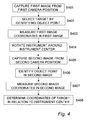
- the method is performed in a surveying instrument comprising a camera and starts with capturing in a step S401 of a first image using said camera in a first camera position and orientation, the first camera position being eccentric to the rotation center of the surveying instrument, after which a target selection is performed in a step S402.
- An object point relating to the target is identified in the first image which may be a snapshot or a frame of a video feed captured by the camera.
- the target may be identified by selection by an operator clicking on a screen showing the image captured by the camera, or in any other suitable way of indicating the selected target with respect to the captured image.
- the target identification can be made in other ways, such as using prisms located at the target, edge detection, identification of target features (e.g. arrows), etc.
- first image coordinates of the object point in the first image are measured in a step S403.
- a step S404 the surveying instrument is rotated around the rotation center so that the camera is moved from the first camera position and orientation to a second camera position and orientation.
- the second camera position is eccentric to the rotation center of the surveying instrument.
- the first camera position and orientation is given by camera calibration data as well as the horizontal and vertical direction of the camera center to the instrument rotation center.
- the first camera position and orientation is determined by taking into account the horizontal and vertical direction of the camera center to the instrument rotation center, i.e. camera calibration data in the form of eccentricity parameters eq and e l , such that camera coordinates are related to surveying instrument coordinates.
- calibration data can be considered, for example camera position independent parameters such as the so-called camera constant representing distance between the camera center and image plane and/or parameter of distortion, which depends on the image position.
- camera position independent parameters such as the so-called camera constant representing distance between the camera center and image plane and/or parameter of distortion, which depends on the image position.
- the second camera position and orientation can be derived from the rotation together with camera calibration data.
- the method then proceeds with capturing in a step S405 a second image using the camera in the second camera position and orientation, after which the object point identified in the first image is identified in a step S406 in the second image.
- the object point may be identified by selection by an operator clicking on a screen showing the image captured by the camera, or preferably by means of digital image processing.
- step S406 second image coordinates of the object point in the second image are measured in a step S407.
- coordinates of the target in relation to the rotation center of the surveying instrument are determined in a step S408 based on the first camera position and orientation, the first image coordinates, the second camera position and orientation, the second image coordinates, and camera calibration data.
- FIG. 5A and 5B A first implementation of a surveying instrument is schematically shown in Figures 5A and 5B .
- the surveying instrument is shown in two dimensions.
- Figures 5A and 5B can be seen as either top or side views.
- teachings of the invention should be expanded to the three-dimensional case.
- the surveying instrument 500 comprises a camera comprising a camera sensor 501 and an optical system 502.
- the camera has a camera center, or projection center, (indicated by O' in figure 5A and O" in figure 5B ) that is eccentric to the location O of the rotation center of the instrument 500.
- the camera may further be moved to different positions by rotation of the surveying instrument 500 around its rotation center.
- the surveying is shown having a single camera since only one camera is required.
- the surveying instrument may well comprise more than one camera, e.g. a second camera used for a separate feature.
- the camera is located above the line of sight of the instrument in the example figures 5A and 5B .
- the camera may have an arbitrary eccentric location with respect to the instrument rotation center.
- a first image is captured by the camera sensor 501, when the camera center is located in a first camera position O' eccentric to the location O of the rotation center of the surveying instrument 500 and having a first camera orientation.
- a target in position P is selected by identifying an object point in a position P' in the first image.
- first image coordinates of the object point in the first image are measured.
- the camera center has been moved from the first position O' and first camera orientation to a second camera position O" and second camera rotation by rotation of the instrument 500 around the rotation center by a rotation angle ⁇ .
- a second image is captured by the camera sensor 501, when the camera center is located in the second camera position O" eccentric to the location O of the rotation center of the surveying instrument 500 and having the second camera orientation.
- the object point identified in the first image is identified also in the second image in a position P".
- coordinates of the target P in relation to the rotation center O of the surveying instrument are determined based on the first camera position and orientation, the first image coordinates, the second camera position and orientation, the second image coordinates, and camera calibration data.
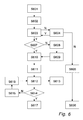
- FIG. 6 is an outline of an implementation of the inventive method performed in a surveying instrument comprising a camera such as schematically disclosed in figures 5A-B .
- Input to the method are camera calibration data comprising camera and surveying instrument parameters.
- the method starts in a step S601 with capturing of a first image using the camera in a first camera position and orientation, said first camera position being eccentric to a rotation center of the surveying instrument, after which in a step S602 a target is selected by identifying an object point in the first image corresponding to the target.
- the target may be identified by selection by an operator clicking on a screen showing the image captured by the camera.
- image coordinates for the object point in the first image are measured.
- step S603 After the object point has been identified, it is determined in a step S603 if the object point can be identified using image processing and recognition software. If it cannot it is determined if a pattern in the vicinity of the point is detectable. If this is not the case the uncertainty is displayed in a step S605 and suitable alternative method is used in a step S606.
- a pattern can be detected or if the point can be identified by software it is determined in a step S607 if the object point is close enough to a closest corner of the image, e.g. less than a threshold distance from the closest corner of the first image. This is to ensure that the method produces an accurate enough output. In alternative it may be determined if the object point is far enough from a point in the image corresponding to the center of the camera detector, e.g. more than a threshold distance from the point in the image corresponding to the center of the camera detector
- a shortest distance (corresponding to a largest difference between the direction from eccentric positioned camera to target and the rotation center of the surveying instrument) is assumed and rotation angles are calculated which will result in the object point being located closer than a threshold to a closest corner in a revised first image but still within the revised first image.
- the surveying instrument is then rotated in accordance with the rotation angles and the revised first image is captured.
- the so called epipolar line can be identified in the revised first image on which epoipolar line the object point should be located in the revised first image.
- the object point is identified by searching along the epipolar line in the revised first image and the first image coordinates are revised as the measured image coordinates of the object point in the revised first image.
- rotation angles are calculated based on camera calibration data, the first camera position and orientation, and the first image coordinates, which rotation angles will result in the object point being located closer than a threshold to a corner of a second image but still within the second image, said corner of the second image being different than the corner of the first image to which the object point is closer than a threshold in the first image and preferably diametrically opposed to that corner.
- the surveying instrument is then rotated in a step S611 according to the rotation angles and the second image is captured using the camera in a second camera position and orientation resulting from the rotation.
- the object point identified in the first image is identified S612 in the second image.
- the so called epipolar line can be identified in the second image on which epipolar line the object point is located in the second image.
- the object point is identified by searching along the epipolar line in the second image. For example, the object point may be identified by selection by an operator clicking on a screen showing the second image, or preferably by means of digital image processing.
- second coordinates of the object point in the second image are measured in a step S612.
- Coordinates of the target in relation to the rotation center of the surveying instrument are determined based on the first camera position and orientation (or revised first camera position and orientation), the first image coordinates, the second camera position and orientation, the second image coordinates, and camera calibration data.
- the coordinates of the target in relation to the rotation center of the surveying instrument are determined based on the first camera position and orientation, the first image coordinates, the second camera position and orientation, the second image coordinates, and camera calibration data.
- a target direction from the rotation center of the surveying instrument is determined based on the determined target coordinates in relation to the rotation center of the surveying instrument. That is, the coordinates of the target are expressed in relation to the coordinate system of the surveying instrument.
- the target coordinates are typically related to a coordinate system having its origin at the rotation center of the surveying instrument.
- a step S613 the distance from the instrument rotation center to the target is determined based on the target coordinates in relation to the rotation center of the surveying instrument.
- a step S614 it is determined if the accuracy of the distance and/or the direction is enough. If it is not, suitable rotation angles for additional measurement is determined in a step S615, the surveying instrument is rotated according to the suitable rotation angles and a revised second image is capture in a step S616, and the method proceeds to the step S612.
- the surveying instrument is rotated so that the line of sight of the instrument rotation center is aimed in the target direction determined in the step S617.
- Figures 7A and 7B show two different images indicating image corners 701, an object point 702 and four areas 703 in each image where the accuracy of the determined target distance and/or direction is considered to be good enough.
- the object point 702 is considered to be close enough (i.e. within area 703) to the corner 701.
- figure 7B illustrates a situation where the object point 702 not is located in one of the four areas 703, wherein the accuracy not is considered to be good enough.
- Figure 8 illustrates an alternative to the thresholding approach of figures 7A and 7B .
- it may be determined if the object point 802 is far enough from a point in the image corresponding to the center of the camera detector, e.g. more than a threshold distance from the point in the image corresponding to the center of the camera detector.
- the shaded area 803 indicates a far enough distance from the center. If so, the accuracy is considered to be good enough.
- Figure 9 schematically illustrates the capturing of two images from a camera using rotation of a surveying instrument between the capturing of a first image and a second image, and identification of an object point along a section of an epipolar line in the second image.
- the camera has a camera center, or projection center, that is eccentric to the location O of the rotation center of the instrument.
- the camera may further be moved to different camera positions and orientations by rotation of the surveying instrument around its rotation center. For each rotation the camera center will be located on a sphere.
- a first image is captured by the camera, when the camera center is located in a first position O' eccentric to the location O of the rotation center of the surveying instrument and the camera having a first camera orientation.
- a target in position P is selected by identifying an object point in a position P'(x', y') in the first image.
- the camera center is then moved from the first camera position O' and orientation to a second camera position O" and orientation by rotation of the instrument around the rotation center.
- the distance between the first and the second camera position is denoted d c .
- a second image is captured by the camera, when the camera center is located in the second position O" eccentric to the location O of the rotation center of the surveying instrument and the camera having the second camera orientation.
- the object point identified in the first image is identified in the second image in a position P"(x" y").
- collinearity equations are used to estimate the coordinates of P.
- collinearity equations For a background of the deriving of the collinearity equations and of calibration of a camera reference is made to WO 2005/059473 .
- X, Y, Z are the coordinates of P. Hence, there are three unknowns and four equations.
- X, Y, Z can be determined with a least square method. It should be noted that there is no limitation to two images to estimate the location of point P, but at least two images are necessary. Hence, two or more images may be used.
- a first direction r' to the target from the first position O' of the camera center can determined.
- a section of r' can then be transformed into a section of a so called epipolar line el" in the second image on which the object point should be located in the second image.
- this pattern may be recognized in the second image, e.g. by means of automatic image processing, by searching along the section of the epipolar line in the second image or in an area around that section. If in alternative, an operator is to identify the target in the second image, the identification can be simplified by graphical indication of the section of the epipolar line in the second image.
- a first image is captured by the camera, when the camera center is located in a first position O' eccentric to the location O of the rotation center of the surveying instrument and the camera having a first camera orientation.
- a target in position P is selected by identifying an object point in a position P'(x', y') in the first image.
- the camera center is then moved from the first camera position O' and orientation to a second camera position O" and orientation by a 180-degree rotation around one rotational axis of the rotation center, e.g. the horizontal axis, followed by a further 180-degree rotation around the other rotational axis of the rotation center, i.e. the vertical axis.
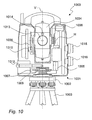
- the total station 1000 shown in figure 10 comprises an alidade 1001 mounted on a base 1002, and has a mounting support structure in the form of a tripod 1003.
- the alidade 1001 can be rotated about a vertically oriented rotation axis V, in order to aim the instrument in any desired horizontal direction.
- a center unit 1004 which can be rotated about a horizontally oriented rotation axis H, in order to aim the instrument in any desired vertical direction.
- Measurements made using the total station 1000 are typically related to an origin of coordinates located at the intersection between the vertically oriented and the horizontally oriented rotation axes V and H.
- drive means 1005 For rotation of the alidade about the vertically oriented rotation axis to aim the instrument in any desired horizontal direction, there is provided drive means 1005.
- the rotational position of the alidade 1001 is tracked by means of a graduated disc 1006 and a corresponding angle encoder or sensor 1007.
- the instrument has an optical plummet 1012, which gives a downwards view along the vertically oriented rotation axis.
- the optical plummet is used by the operator to center or position the instrument above any desired point on the ground.
- the instrument line of sight is centered at the intersection between the vertical and the horizontal rotation axes, and this can be seen in the figure where these axes cross in the center of a telescope 1013 in the center unit 1004.
- a camera 1014 for capturing an image or a video feed generally in the direction of the instrument line of sight.
- the camera 1014 is eccentric from the center of the telescope 1013; in this case, the camera is mounted vertically above the telescope.
- the instrument also comprises a display device for showing the image captured by the camera.
- the display may be an integral part of the instrument, but more preferably, the display is included in a removable control panel that can be used for remote control of the instrument via short range radio. It is even conceivable that the instrument is fully remote controlled, wherein the display may be in the form of a computer screen located far away from the total station, and wherein information to and from the instrument are transferred over a wireless computer or radio telephone network.
- the instrument can also be manually operated for aiming towards a desired target using vertical and horizontal motion servo knobs 1015 and 1016.
- the camera of the instrument is operable to capture images from different positions and orientations eccentric to a rotation center of the surveying instrument.
- the instrument further comprises means for identifying an object point corresponding to a selected target in the displayed image; means for determining, based on the position of the object point in the displayed images, directions towards the target from the camera in the different positions; means for measuring image coordinates of the object point in the displayed images, and means for determining target coordinates of the target in relation to the rotation center of the surveying instrument, based on the first camera position and orientation, the first image coordinates, the second camera position and orientation, the second image coordinates, and camera calibration data.
- the means for identifying the object point in the captured image may take the form of a cursor that can be moved across the display.
- the display may be a touch display, where the object point is identified by simply clicking or tapping on the display. This is preferred for the identification of the object point in the first image.
- the means for identifying the object point may include further functionality implemented in the form of image processing software.
- the further functionality would be that object points may be identified based on certain features in the captured image, for example markers or patterns located at the desired target. For example, an object point identified in a first image may be automatically identified in a second image based on patterns identified in the first image.
- the user may be given the option to give a confirmation that the identified object point is correct before or during the aiming and measuring procedures. This is preferred for the identification of the object point in the second image.
- the means for measuring image coordinates of the object point in the displayed images, and the means for determining target coordinates of the target in relation to the rotation center of the surveying instrument are preferably implemented in the form of computer program code that is executed in a processor. However, implementation may also be made in dedicated hardware, such as in a special purpose microprocessor or a digital signal processor (DSP), firmware or similar.
- DSP digital signal processor
- the means for rotating the instrument is preferably implemented in association with the servo control system for the instrument for controlled activation of the drive motors 1005 and 1008 (see figure 10 ).
Landscapes
- Engineering & Computer Science (AREA)
- Physics & Mathematics (AREA)
- General Physics & Mathematics (AREA)
- Radar, Positioning & Navigation (AREA)
- Remote Sensing (AREA)
- Multimedia (AREA)
- Length Measuring Devices By Optical Means (AREA)
Claims (15)
- Verfahren zur Bestimmung von Koordinaten eines Ziels (P) in Bezug auf ein Vermessungsinstrument (500) mit einer Kamera (cam, 101, 103), umfassend:Erfassen (S401) eines ersten Bildes unter Verwendung der Kamera in einer ersten Kameraposition und -ausrichtung, wobei die erste Kameraposition exzentrisch zu einem Drehmittelpunkt des Vermessungsinstruments ist;Auswählen (S402) eines Ziels durch Identifizieren eines Objektpunkts im ersten Bild;Messen (S403) von ersten Bildkoordinaten des Objektpunkts im ersten Bild;Drehen (S404) des Vermessungsinstruments um den Drehmittelpunkt, so dass die Kamera aus der ersten Kameraposition und -ausrichtung in eine zweite Kameraposition und -ausrichtung bewegt wird, während der Drehmittelpunkt des Vermessungsinstruments in einer festen Position gehalten wird, wobei die zweite Kameraposition exzentrisch zum Drehmittelpunkt des Vermessungsinstruments ist;Erfassen (S405) eines zweiten Bildes unter Verwendung der Kamera in der zweiten Kameraposition und -ausrichtung;Identifizieren (S406) im zweiten Bild des im ersten Bild identifizierten Objektpunkts, ferner umfassend:Auswählen eines Mindestabstands (Dmin) und eines Höchstabstands (Dmax) von der ersten Kameraposition entlang eines Abbildungsstrahls des Ziels im ersten Bild, wobei sich das Ziel zwischen dem Mindestabstand und Höchstabstand befindet;Bestimmen einer Teilstrecke einer Epipolarlinie (el) im zweiten Bild, auf der sich der Objektpunkt befindet, basierend auf dem Höchstabstand, dem Mindestabstand, der ersten Kameraposition und -ausrichtung, der zweiten Kameraposition und -ausrichtung, den ersten Bildkoordinaten und Kamerakalibrierdaten; undIdentifizieren entlang der Teilstrecke der Epipolarlinie im zweiten Bild des im ersten Bild identifizierten Objektpunkts;Messen (S407) von zweiten Bildkoordinaten des Objektpunkts im zweiten Bild; undBestimmen (S408) von Zielkoordinaten des Ziels in Bezug auf den Drehmittelpunkt des Vermessungsinstruments basierend auf der ersten Kameraposition und -ausrichtung, den ersten Bildkoordinaten, der zweiten Kameraposition und -ausrichtung, den zweiten Bildkoordinaten und Kamerakalibrierdaten.
- Verfahren nach Anspruch 1, wobei der Mindestabstand als der Mindestabstand des Vermessungsinstruments ausgewählt wird.
- Verfahren nach einem der Ansprüche 1 oder 2, wobei, wenn der identifizierte Objektpunkt nicht näher als ein Schwellenabstand von einer nächstgelegenen Ecke des ersten Bildes ist, die folgenden Schritte ausgeführt werden:Bestimmen basierend auf der Position des Objektpunkts im ersten Bild einer revidierten Drehung des Vermessungsinstruments um den Drehmittelpunkt, die dazu führt, dass der Objektpunkt näher als ein Schwellenabstand von einer nächstgelegenen Ecke eines Bildes ist, das mit der Kamera nach der revidierten Drehung erfasst wird;Drehen des Vermessungsinstruments um die revidierte Drehung um den Drehmittelpunkt, so dass die Kamera aus der ersten Kameraposition und -ausrichtung in eine revidierte Kameraposition und -ausrichtung bewegt wird;Erfassen eines revidierten ersten Bildes unter Verwendung der Kamera in der revidierten ersten Position und Ausrichtung;Identifizieren im revidierten ersten Bild des im ersten Bild identifizierten Objektpunkts;Revidieren der ersten Bildkoordinaten in gemessene Bildkoordinaten des Objektpunkts im revidierten ersten Bild.
- Verfahren nach Anspruch 3, wobei das Identifizieren im revidierten ersten Bild des im ersten Bild identifizierten Objektpunkts umfasst:Bestimmen einer Epipolarlinie im revidierten ersten Bild, auf der sich der Objektpunkt befindet, basierend auf der ersten Kameraposition und -ausrichtung, der revidierten Kameraposition und -ausrichtung, den ersten Bildkoordinaten und Kamerakalibrierdaten; undIdentifizieren entlang der Epipolarlinie im revidierten ersten Bild des im ersten Bild identifizierten Objektpunkts.
- Verfahren nach Anspruch 4, wobei das Identifizieren im revidierten ersten Bild des im ersten Bild identifizierten Objektpunkts umfasst:Auswählen eines Mindestabstands und eines Höchstabstands von der ersten Kameraposition entlang des Abbildungsstrahls des Ziels im ersten Bild, wobei sich das Ziel zwischen dem Mindestabstand und Höchstabstand befindet;Bestimmend basierend auf dem Höchstabstand und dem Mindestabstand einer Teilstrecke der Epipolarlinie im revidierten ersten Bild, auf welcher sich der Objektpunkt befindet; undIdentifizieren entlang der Teilstrecke der Epipolarlinie im revidierten ersten Bild des im ersten Bild identifizierten Objektpunkts.
- Verfahren nach einem der Ansprüche 1 bis 5, wobei der Objektpunkt im ersten Bild durch Bedienerauswahl identifiziert wird.
- Verfahren nach einem der Ansprüche 1 bis 6, wobei der Objektpunkt im ersten Bild durch automatische Bildanalyse identifiziert wird.
- Verfahren nach einem der Ansprüche 1 bis 7, wobei der im ersten Bild identifizierte Objektpunkt im zweiten Bild durch automatische Bildanalyse identifiziert wird.
- Verfahren nach einem der Ansprüche 1 bis 8, wobei der im ersten Bild identifizierte Objektpunkt im zweiten Bild durch Benutzerauswahl identifiziert wird.
- Verfahren nach einem der Ansprüche 1 bis 9, ferner umfassend:Bestimmen einer Richtung vom Drehmittelpunkt des Vermessungsinstruments zum Ziel basierend auf den bestimmten Koordinaten des Ziels.
- Verfahren nach Anspruch 10, ferner umfassend:Drehen des Vermessungsinstruments, so dass eine Sichtlinie des Vermessungsinstruments in Richtung Ziel gerichtet wird.
- Verfahren nach Anspruch 11, ferner umfassend:Messen eines Abstands zum Ziel unter Verwendung von Abstandsmessfähigkeiten innerhalb des Vermessungsinstruments.
- Verfahren nach einem der Ansprüche 1 bis 12, ferner umfassend:Bestimmen eines Abstands vom Drehmittelpunkt des Vermessungsinstruments zum Ziel basierend auf den bestimmten Zielkoordinaten.
- Verfahren nach einem der Ansprüche 1 bis 13, wobei die derartige Drehung des Vermessungsinstruments um den Drehmittelpunkt, dass die Kamera aus der ersten Kameraposition und -ausrichtung in eine zweite Kameraposition und -ausrichtung bewegt wird, umfasst:Drehen des Vermessungsinstruments 180 Grad um eine erste der zwei Drehachsen des Drehmittelpunkts; undDrehen des Vermessungsinstruments 180 Grad um eine zweite der zwei Drehachsen des Drehmittelpunkts.
- Vermessungsinstrument, umfassend:eine Kamera, die so ausgelegt ist, dass sie Bilder aus verschiedenen Positionen und Ausrichtungen exzentrisch zu einem Drehmittelpunkt des Vermessungsinstruments erfasst, während der Drehmittelpunkt des Vermessungsinstruments in einer festen Position gehalten wird;Mittel zum Anzeigen von Bildern, die von der Kamera aus den verschiedenen Positionen und Ausrichtungen erfasst werden;Mittel zum Identifizieren eines Objektpunkts, der einem ausgewählten Ziel in den angezeigten Bildern entspricht, wobei das Mittel zum Identifizieren ausgelegt ist zum:Auswählen eines Mindestabstands und eines Höchstabstands von der ersten Kameraposition entlang eines Abbildungsstrahls des Ziels im ersten Bild, wobei sich das Ziel zwischen dem Mindestabstand und Höchstabstand befindet;Bestimmen einer Teilstrecke einer Epipolarlinie im zweiten Bild, auf der sich der Objektpunkt befindet, basierend auf dem Höchstabstand, dem Mindestabstand, der ersten Kameraposition und -ausrichtung, der zweiten Kameraposition und -ausrichtung, den ersten Bildkoordinaten und Kamerakalibrierdaten; undIdentifizieren entlang der Teilstrecke der Epipolarlinie im zweiten Bild des im ersten Bild identifizierten Objektpunkts, undMittel zum Messen von Bildkoordinaten des Objektpunkts in den angezeigten Bildern;Mittel zum Drehen des Vermessungsinstruments um den Drehmittelpunkt des Vermessungsinstruments; undMittel zum Bestimmen von Koordinaten des Ziels in Bezug auf den Drehmittelpunkt des Vermessungsinstruments basierend auf der ersten Kameraposition und -ausrichtung, den ersten Bildkoordinaten, der zweiten Kameraposition und -ausrichtung, den zweiten Bildkoordinaten und Kamerakalibrierdaten.
Applications Claiming Priority (1)
| Application Number | Priority Date | Filing Date | Title |
|---|---|---|---|
| PCT/EP2008/001053 WO2009100728A1 (en) | 2008-02-12 | 2008-02-12 | Determining coordinates of a target in relation to a survey instruments having a camera |
Publications (2)
| Publication Number | Publication Date |
|---|---|
| EP2247921A1 EP2247921A1 (de) | 2010-11-10 |
| EP2247921B1 true EP2247921B1 (de) | 2014-10-08 |
Family
ID=39877720
Family Applications (1)
| Application Number | Title | Priority Date | Filing Date |
|---|---|---|---|
| EP08707675.8A Active EP2247921B1 (de) | 2008-02-12 | 2008-02-12 | Bestimmung von koordinaten eines ziels in bezug auf vermessungsinstrumente mit einer kamera |
Country Status (4)
| Country | Link |
|---|---|
| US (1) | US8625086B2 (de) |
| EP (1) | EP2247921B1 (de) |
| CN (1) | CN101946156B (de) |
| WO (1) | WO2009100728A1 (de) |
Families Citing this family (52)
| Publication number | Priority date | Publication date | Assignee | Title |
|---|---|---|---|---|
| EP2240740B1 (de) | 2008-02-12 | 2014-10-08 | Trimble AB | Lokalisierung eines vermessungsinstruments in bezug auf eine bodenmarkierung |
| US8897482B2 (en) | 2008-02-29 | 2014-11-25 | Trimble Ab | Stereo photogrammetry from a single station using a surveying instrument with an eccentric camera |
| US9189858B2 (en) | 2008-02-29 | 2015-11-17 | Trimble Ab | Determining coordinates of a target in relation to a survey instrument having at least two cameras |
| US9482755B2 (en) | 2008-11-17 | 2016-11-01 | Faro Technologies, Inc. | Measurement system having air temperature compensation between a target and a laser tracker |
| JP5421624B2 (ja) * | 2009-03-16 | 2014-02-19 | 株式会社トプコン | 三次元計測用画像撮影装置 |
| TWI420066B (zh) | 2010-03-18 | 2013-12-21 | Ind Tech Res Inst | 物件量測方法與系統 |
| US9377885B2 (en) | 2010-04-21 | 2016-06-28 | Faro Technologies, Inc. | Method and apparatus for locking onto a retroreflector with a laser tracker |
| US8724119B2 (en) | 2010-04-21 | 2014-05-13 | Faro Technologies, Inc. | Method for using a handheld appliance to select, lock onto, and track a retroreflector with a laser tracker |
| US8422034B2 (en) | 2010-04-21 | 2013-04-16 | Faro Technologies, Inc. | Method and apparatus for using gestures to control a laser tracker |
| US8619265B2 (en) | 2011-03-14 | 2013-12-31 | Faro Technologies, Inc. | Automatic measurement of dimensional data with a laser tracker |
| US9400170B2 (en) | 2010-04-21 | 2016-07-26 | Faro Technologies, Inc. | Automatic measurement of dimensional data within an acceptance region by a laser tracker |
| US9772394B2 (en) | 2010-04-21 | 2017-09-26 | Faro Technologies, Inc. | Method and apparatus for following an operator and locking onto a retroreflector with a laser tracker |
| US8537371B2 (en) | 2010-04-21 | 2013-09-17 | Faro Technologies, Inc. | Method and apparatus for using gestures to control a laser tracker |
| US9879993B2 (en) | 2010-12-23 | 2018-01-30 | Trimble Inc. | Enhanced bundle adjustment techniques |
| US9182229B2 (en) | 2010-12-23 | 2015-11-10 | Trimble Navigation Limited | Enhanced position measurement systems and methods |
| US10168153B2 (en) | 2010-12-23 | 2019-01-01 | Trimble Inc. | Enhanced position measurement systems and methods |
| CN103415780B (zh) * | 2011-01-10 | 2015-09-16 | 特林布尔公司 | 用于确定测量仪的位置和定向的方法和系统 |
| GB2518544A (en) | 2011-03-03 | 2015-03-25 | Faro Tech Inc | Target apparatus and method |
| US9686532B2 (en) | 2011-04-15 | 2017-06-20 | Faro Technologies, Inc. | System and method of acquiring three-dimensional coordinates using multiple coordinate measurement devices |
| US9164173B2 (en) | 2011-04-15 | 2015-10-20 | Faro Technologies, Inc. | Laser tracker that uses a fiber-optic coupler and an achromatic launch to align and collimate two wavelengths of light |
| DE112012001708B4 (de) | 2011-04-15 | 2018-05-09 | Faro Technologies, Inc. | Koordinatenmessgerät |
| US9482529B2 (en) | 2011-04-15 | 2016-11-01 | Faro Technologies, Inc. | Three-dimensional coordinate scanner and method of operation |
| DE102011114115A1 (de) * | 2011-09-25 | 2013-03-28 | Zdenko Kurtovic | Verfahren und Anordnung zur Bestimmung der Lage eines Meßpunktes im geometrischen Raum |
| JP6099675B2 (ja) | 2012-01-27 | 2017-03-22 | ファロ テクノロジーズ インコーポレーテッド | バーコード識別による検査方法 |
| US9439747B2 (en) * | 2012-02-22 | 2016-09-13 | Boston Scientific Scimed, Inc. | Adjustable medical assembly for implant tension adjustment |
| US9235763B2 (en) | 2012-11-26 | 2016-01-12 | Trimble Navigation Limited | Integrated aerial photogrammetry surveys |
| DE102013107597A1 (de) | 2013-01-11 | 2014-08-14 | Stephan Hörmann | Vermessungsverfahren für gebäudeöffnungen und gebäudeabschlussherstellverfahren sowie vorrichtungen zur durchführung derselben |
| DE102013016486A1 (de) | 2013-09-13 | 2015-04-02 | Stephan Hörmann | Vermessungsverfahren für Gebäudeöffnungen und Gebäudeabschlussherstellverfahren sowie Vorrichtungen zur Durchführung derselben |
| US9041914B2 (en) | 2013-03-15 | 2015-05-26 | Faro Technologies, Inc. | Three-dimensional coordinate scanner and method of operation |
| CN103245322B (zh) * | 2013-04-10 | 2015-11-11 | 南京航空航天大学 | 一种基于双目立体视觉的测距方法及系统 |
| EP2994025B1 (de) | 2013-05-05 | 2023-09-20 | Trax Technology Solutions Pte Ltd. | System und verfahren zur überwachung von verkaufseinheiten |
| US9247239B2 (en) | 2013-06-20 | 2016-01-26 | Trimble Navigation Limited | Use of overlap areas to optimize bundle adjustment |
| IL228735B (en) | 2013-10-06 | 2018-10-31 | Israel Aerospace Ind Ltd | A system and method for determining target direction |
| US20150187101A1 (en) * | 2013-12-30 | 2015-07-02 | Trax Technology Solutions Pte Ltd. | Device and method with orientation indication |
| CN104754323B (zh) * | 2013-12-31 | 2017-06-20 | 苏州智华汽车电子有限公司 | 摄像头光轴检测设备的标定方法 |
| US10387996B2 (en) | 2014-02-02 | 2019-08-20 | Trax Technology Solutions Pte Ltd. | System and method for panoramic image processing |
| US10402777B2 (en) | 2014-06-18 | 2019-09-03 | Trax Technology Solutions Pte Ltd. | Method and a system for object recognition |
| US9395174B2 (en) | 2014-06-27 | 2016-07-19 | Faro Technologies, Inc. | Determining retroreflector orientation by optimizing spatial fit |
| TWI586936B (zh) * | 2016-05-20 | 2017-06-11 | 國立交通大學 | 實體影像與虛擬影像之間轉換的方法及其系統 |
| CN106060527B (zh) * | 2016-08-01 | 2018-10-19 | 北京小鸟看看科技有限公司 | 一种扩展双目相机定位范围的方法和装置 |
| CN106331618B (zh) * | 2016-08-22 | 2019-07-16 | 浙江宇视科技有限公司 | 一种自动确认摄像机可视域的方法及装置 |
| US10586349B2 (en) | 2017-08-24 | 2020-03-10 | Trimble Inc. | Excavator bucket positioning via mobile device |
| CN110310334B (zh) * | 2018-03-20 | 2023-05-16 | 深圳市华大智造软件技术有限公司 | 生物芯片定位方法、基因测序仪及系统、存储介质 |
| RU2685761C1 (ru) * | 2018-09-09 | 2019-04-23 | Дмитрий Александрович Рощин | Фотограмметрический способ измерения расстояний вращением цифрового фотоаппарата |
| CN110555888B (zh) * | 2019-08-22 | 2022-10-04 | 浙江大华技术股份有限公司 | 主从相机标定方法、存储装置、计算机设备及其系统 |
| US10943360B1 (en) | 2019-10-24 | 2021-03-09 | Trimble Inc. | Photogrammetric machine measure up |
| CN110927118B (zh) * | 2019-10-28 | 2022-07-15 | 航天新气象科技有限公司 | 植被指数测量仪、控制方法及测量方法 |
| CN112735245A (zh) * | 2020-12-16 | 2021-04-30 | 江苏师范大学 | 一种用于近景摄影测量教学与测试的觇标装置及方法 |
| CN113029087B (zh) * | 2021-04-27 | 2022-10-25 | 江南造船(集团)有限责任公司 | 一种船体基座空间安装角度测量方法 |
| CN113936062B (zh) * | 2021-10-22 | 2025-03-04 | 郑州恒达智控科技股份有限公司 | 采煤工作面液压支架护帮板定位方法 |
| CN115452101B (zh) * | 2022-09-02 | 2025-03-14 | 上海肯特仪表股份有限公司 | 一种仪表检定方法、装置、设备及介质 |
| CN116301062B (zh) * | 2023-03-27 | 2025-05-06 | 中国科学院光电技术研究所 | 一种基于三点坐标的望远镜固定像旋解算方法 |
Family Cites Families (30)
| Publication number | Priority date | Publication date | Assignee | Title |
|---|---|---|---|---|
| DD144967A1 (de) | 1979-07-16 | 1980-11-12 | Harry Wendt | Verfahren zur bestimmung der instrumentenhoehe bei elektromagnetischen entfernungsmessern |
| JP2945467B2 (ja) | 1990-11-29 | 1999-09-06 | 株式会社トプコン | 機械高測定装置 |
| US5949548A (en) * | 1997-01-22 | 1999-09-07 | Asahi Kogaku Kogyo Kabushiki Kaisha | Height sensing measurement device |
| US6442293B1 (en) * | 1998-06-11 | 2002-08-27 | Kabushiki Kaisha Topcon | Image forming apparatus, image forming method and computer-readable storage medium having an image forming program |
| JP3685621B2 (ja) | 1998-06-17 | 2005-08-24 | 株式会社日立コミュニケーションテクノロジー | プリント板構造 |
| JP3965593B2 (ja) | 1998-07-08 | 2007-08-29 | 株式会社トプコン | 測量機の求心位置測定装置及び測量機 |
| AT406422B (de) | 1998-10-27 | 2000-05-25 | Geodata Ziviltech Gmbh | Theodolit |
| JP2000131060A (ja) * | 1998-10-29 | 2000-05-12 | Mitsubishi Electric Corp | 測量装置及び測量方法 |
| JP2002535638A (ja) * | 1999-01-19 | 2002-10-22 | ライカ ジオシステムズ アクチエンゲゼルシャフト | 測地器具の高さ位置を決定するシステム |
| JP4198809B2 (ja) | 1999-01-21 | 2008-12-17 | セイレイ工業株式会社 | コンバインの燃料給油装置 |
| DE59903391D1 (de) * | 1999-01-27 | 2002-12-19 | Leica Geosystems Ag | Vermessungsgerät mit einer Höhenmesseinrichtung |
| DE19941638C1 (de) * | 1999-08-27 | 2000-12-14 | Zeiss Carl Jena Gmbh | Geodätisches Gerät mit Laseranordnung |
| ATE346278T1 (de) * | 2000-03-30 | 2006-12-15 | Topcon Corp | Stereobildmessvorrichtung |
| KR20020097172A (ko) * | 2001-02-08 | 2002-12-31 | 닛폰 고칸 가부시키가이샤 | 3차원 좌표 계측방법, 3차원 좌표 계측장치 및 대형구조물의 건조방법 |
| SE525290C2 (sv) | 2002-12-20 | 2005-01-25 | Trimble Ab | Geodetiskt system för mätning/utsättning och metod för användning av detsamma |
| AU2003223166A1 (en) * | 2003-02-25 | 2004-09-28 | Chen, Chung-Chin | Photographic type pointer postioning device |
| CN1567384A (zh) | 2003-06-27 | 2005-01-19 | 史中超 | 三维空间物体图像获取、数字化测量及重建方法和设备 |
| US20060167648A1 (en) * | 2003-08-13 | 2006-07-27 | Hitoshi Ohtani | 3-Dimensional measurement device and electronic storage medium |
| US20050057745A1 (en) | 2003-09-17 | 2005-03-17 | Bontje Douglas A. | Measurement methods and apparatus |
| DE10359415A1 (de) | 2003-12-16 | 2005-07-14 | Trimble Jena Gmbh | Verfahren zur Kalibrierung eines Vermessungsgeräts |
| JP4529157B2 (ja) * | 2004-06-15 | 2010-08-25 | 株式会社トプコン | 3次元測量システム及び電子的記憶媒体 |
| JP4424665B2 (ja) * | 2004-07-30 | 2010-03-03 | 株式会社 ソキア・トプコン | 測量機 |
| US7697749B2 (en) * | 2004-08-09 | 2010-04-13 | Fuji Jukogyo Kabushiki Kaisha | Stereo image processing device |
| JP4649192B2 (ja) * | 2004-12-14 | 2011-03-09 | 株式会社トプコン | ステレオ画像作成方法及び3次元データ作成装置 |
| US20070065004A1 (en) * | 2005-08-01 | 2007-03-22 | Topcon Corporation | Three-dimensional measurement system and method of the same, and color-coded mark |
| JP2007147422A (ja) | 2005-11-28 | 2007-06-14 | Komatsu Engineering Corp | 計測システム、画像処理装置及び方法 |
| JP2008014653A (ja) * | 2006-07-03 | 2008-01-24 | Pentax Industrial Instruments Co Ltd | 測量機 |
| EP2084491A2 (de) * | 2006-11-21 | 2009-08-05 | Mantisvision Ltd. | Geometrische modellierung in 3d und videoinhaltserzeugung in 3d |
| EP2240740B1 (de) | 2008-02-12 | 2014-10-08 | Trimble AB | Lokalisierung eines vermessungsinstruments in bezug auf eine bodenmarkierung |
| US9189858B2 (en) | 2008-02-29 | 2015-11-17 | Trimble Ab | Determining coordinates of a target in relation to a survey instrument having at least two cameras |
-
2008
- 2008-02-12 US US12/735,582 patent/US8625086B2/en active Active
- 2008-02-12 WO PCT/EP2008/001053 patent/WO2009100728A1/en not_active Ceased
- 2008-02-12 EP EP08707675.8A patent/EP2247921B1/de active Active
- 2008-02-12 CN CN2008801265892A patent/CN101946156B/zh active Active
Also Published As
| Publication number | Publication date |
|---|---|
| US20110007154A1 (en) | 2011-01-13 |
| WO2009100728A1 (en) | 2009-08-20 |
| CN101946156B (zh) | 2012-09-19 |
| CN101946156A (zh) | 2011-01-12 |
| US8625086B2 (en) | 2014-01-07 |
| EP2247921A1 (de) | 2010-11-10 |
Similar Documents
| Publication | Publication Date | Title |
|---|---|---|
| US8625086B2 (en) | Determining coordinates of a target in relation to a survey instrument having a camera | |
| EP2240740B1 (de) | Lokalisierung eines vermessungsinstruments in bezug auf eine bodenmarkierung | |
| US7930835B2 (en) | Aiming of a geodetic instrument | |
| EP2247922B1 (de) | Bestimmung von koordinaten eines ziels in bezug auf ein vermessungsinstrument mit mindestens zwei kameras | |
| US8897482B2 (en) | Stereo photogrammetry from a single station using a surveying instrument with an eccentric camera | |
| CN1761855B (zh) | 大地测量仪器中的图像处理方法和装置 | |
| EP2141451B1 (de) | Mehrpunktmessverfahren und abfrageinstrument | |
| CA2811444A1 (en) | Geodetic survey system having a camera integrated in a remote control unit | |
| JP4944462B2 (ja) | 地理データ収集装置 | |
| CN101568800B (zh) | 测地仪器和相关方法 | |
| JP4359083B2 (ja) | 測量システム | |
| JP4167509B2 (ja) | 測量システム |
Legal Events
| Date | Code | Title | Description |
|---|---|---|---|
| PUAI | Public reference made under article 153(3) epc to a published international application that has entered the european phase |
Free format text: ORIGINAL CODE: 0009012 |
|
| 17P | Request for examination filed |
Effective date: 20100910 |
|
| AK | Designated contracting states |
Kind code of ref document: A1 Designated state(s): AT BE BG CH CY CZ DE DK EE ES FI FR GB GR HR HU IE IS IT LI LT LU LV MC MT NL NO PL PT RO SE SI SK TR |
|
| AX | Request for extension of the european patent |
Extension state: AL BA MK RS |
|
| DAX | Request for extension of the european patent (deleted) | ||
| RIC1 | Information provided on ipc code assigned before grant |
Ipc: G01C 11/06 20060101ALI20140318BHEP Ipc: G01C 1/04 20060101AFI20140318BHEP Ipc: G01C 15/00 20060101ALI20140318BHEP |
|
| GRAP | Despatch of communication of intention to grant a patent |
Free format text: ORIGINAL CODE: EPIDOSNIGR1 |
|
| INTG | Intention to grant announced |
Effective date: 20140520 |
|
| GRAS | Grant fee paid |
Free format text: ORIGINAL CODE: EPIDOSNIGR3 |
|
| GRAA | (expected) grant |
Free format text: ORIGINAL CODE: 0009210 |
|
| AK | Designated contracting states |
Kind code of ref document: B1 Designated state(s): AT BE BG CH CY CZ DE DK EE ES FI FR GB GR HR HU IE IS IT LI LT LU LV MC MT NL NO PL PT RO SE SI SK TR |
|
| REG | Reference to a national code |
Ref country code: GB Ref legal event code: FG4D |
|
| REG | Reference to a national code |
Ref country code: AT Ref legal event code: REF Ref document number: 690871 Country of ref document: AT Kind code of ref document: T Effective date: 20141015 Ref country code: CH Ref legal event code: EP |
|
| REG | Reference to a national code |
Ref country code: IE Ref legal event code: FG4D |
|
| REG | Reference to a national code |
Ref country code: DE Ref legal event code: R096 Ref document number: 602008034750 Country of ref document: DE Effective date: 20141120 |
|
| REG | Reference to a national code |
Ref country code: NL Ref legal event code: VDEP Effective date: 20141008 |
|
| REG | Reference to a national code |
Ref country code: AT Ref legal event code: MK05 Ref document number: 690871 Country of ref document: AT Kind code of ref document: T Effective date: 20141008 |
|
| REG | Reference to a national code |
Ref country code: LT Ref legal event code: MG4D |
|
| PG25 | Lapsed in a contracting state [announced via postgrant information from national office to epo] |
Ref country code: NL Free format text: LAPSE BECAUSE OF FAILURE TO SUBMIT A TRANSLATION OF THE DESCRIPTION OR TO PAY THE FEE WITHIN THE PRESCRIBED TIME-LIMIT Effective date: 20141008 |
|
| PG25 | Lapsed in a contracting state [announced via postgrant information from national office to epo] |
Ref country code: IS Free format text: LAPSE BECAUSE OF FAILURE TO SUBMIT A TRANSLATION OF THE DESCRIPTION OR TO PAY THE FEE WITHIN THE PRESCRIBED TIME-LIMIT Effective date: 20150208 Ref country code: NO Free format text: LAPSE BECAUSE OF FAILURE TO SUBMIT A TRANSLATION OF THE DESCRIPTION OR TO PAY THE FEE WITHIN THE PRESCRIBED TIME-LIMIT Effective date: 20150108 Ref country code: ES Free format text: LAPSE BECAUSE OF FAILURE TO SUBMIT A TRANSLATION OF THE DESCRIPTION OR TO PAY THE FEE WITHIN THE PRESCRIBED TIME-LIMIT Effective date: 20141008 Ref country code: LT Free format text: LAPSE BECAUSE OF FAILURE TO SUBMIT A TRANSLATION OF THE DESCRIPTION OR TO PAY THE FEE WITHIN THE PRESCRIBED TIME-LIMIT Effective date: 20141008 Ref country code: PT Free format text: LAPSE BECAUSE OF FAILURE TO SUBMIT A TRANSLATION OF THE DESCRIPTION OR TO PAY THE FEE WITHIN THE PRESCRIBED TIME-LIMIT Effective date: 20150209 Ref country code: FI Free format text: LAPSE BECAUSE OF FAILURE TO SUBMIT A TRANSLATION OF THE DESCRIPTION OR TO PAY THE FEE WITHIN THE PRESCRIBED TIME-LIMIT Effective date: 20141008 |
|
| PG25 | Lapsed in a contracting state [announced via postgrant information from national office to epo] |
Ref country code: AT Free format text: LAPSE BECAUSE OF FAILURE TO SUBMIT A TRANSLATION OF THE DESCRIPTION OR TO PAY THE FEE WITHIN THE PRESCRIBED TIME-LIMIT Effective date: 20141008 Ref country code: SE Free format text: LAPSE BECAUSE OF FAILURE TO SUBMIT A TRANSLATION OF THE DESCRIPTION OR TO PAY THE FEE WITHIN THE PRESCRIBED TIME-LIMIT Effective date: 20141008 Ref country code: LV Free format text: LAPSE BECAUSE OF FAILURE TO SUBMIT A TRANSLATION OF THE DESCRIPTION OR TO PAY THE FEE WITHIN THE PRESCRIBED TIME-LIMIT Effective date: 20141008 Ref country code: GR Free format text: LAPSE BECAUSE OF FAILURE TO SUBMIT A TRANSLATION OF THE DESCRIPTION OR TO PAY THE FEE WITHIN THE PRESCRIBED TIME-LIMIT Effective date: 20150109 Ref country code: PL Free format text: LAPSE BECAUSE OF FAILURE TO SUBMIT A TRANSLATION OF THE DESCRIPTION OR TO PAY THE FEE WITHIN THE PRESCRIBED TIME-LIMIT Effective date: 20141008 Ref country code: CY Free format text: LAPSE BECAUSE OF FAILURE TO SUBMIT A TRANSLATION OF THE DESCRIPTION OR TO PAY THE FEE WITHIN THE PRESCRIBED TIME-LIMIT Effective date: 20141008 Ref country code: HR Free format text: LAPSE BECAUSE OF FAILURE TO SUBMIT A TRANSLATION OF THE DESCRIPTION OR TO PAY THE FEE WITHIN THE PRESCRIBED TIME-LIMIT Effective date: 20141008 |
|
| PG25 | Lapsed in a contracting state [announced via postgrant information from national office to epo] |
Ref country code: BE Free format text: LAPSE BECAUSE OF NON-PAYMENT OF DUE FEES Effective date: 20150228 |
|
| REG | Reference to a national code |
Ref country code: DE Ref legal event code: R097 Ref document number: 602008034750 Country of ref document: DE |
|
| PG25 | Lapsed in a contracting state [announced via postgrant information from national office to epo] |
Ref country code: DK Free format text: LAPSE BECAUSE OF FAILURE TO SUBMIT A TRANSLATION OF THE DESCRIPTION OR TO PAY THE FEE WITHIN THE PRESCRIBED TIME-LIMIT Effective date: 20141008 Ref country code: CZ Free format text: LAPSE BECAUSE OF FAILURE TO SUBMIT A TRANSLATION OF THE DESCRIPTION OR TO PAY THE FEE WITHIN THE PRESCRIBED TIME-LIMIT Effective date: 20141008 Ref country code: SK Free format text: LAPSE BECAUSE OF FAILURE TO SUBMIT A TRANSLATION OF THE DESCRIPTION OR TO PAY THE FEE WITHIN THE PRESCRIBED TIME-LIMIT Effective date: 20141008 Ref country code: RO Free format text: LAPSE BECAUSE OF FAILURE TO SUBMIT A TRANSLATION OF THE DESCRIPTION OR TO PAY THE FEE WITHIN THE PRESCRIBED TIME-LIMIT Effective date: 20141008 Ref country code: EE Free format text: LAPSE BECAUSE OF FAILURE TO SUBMIT A TRANSLATION OF THE DESCRIPTION OR TO PAY THE FEE WITHIN THE PRESCRIBED TIME-LIMIT Effective date: 20141008 |
|
| PLBE | No opposition filed within time limit |
Free format text: ORIGINAL CODE: 0009261 |
|
| STAA | Information on the status of an ep patent application or granted ep patent |
Free format text: STATUS: NO OPPOSITION FILED WITHIN TIME LIMIT |
|
| PG25 | Lapsed in a contracting state [announced via postgrant information from national office to epo] |
Ref country code: IT Free format text: LAPSE BECAUSE OF FAILURE TO SUBMIT A TRANSLATION OF THE DESCRIPTION OR TO PAY THE FEE WITHIN THE PRESCRIBED TIME-LIMIT Effective date: 20141008 |
|
| 26N | No opposition filed |
Effective date: 20150709 |
|
| PG25 | Lapsed in a contracting state [announced via postgrant information from national office to epo] |
Ref country code: LU Free format text: LAPSE BECAUSE OF FAILURE TO SUBMIT A TRANSLATION OF THE DESCRIPTION OR TO PAY THE FEE WITHIN THE PRESCRIBED TIME-LIMIT Effective date: 20150212 |
|
| REG | Reference to a national code |
Ref country code: CH Ref legal event code: PL |
|
| GBPC | Gb: european patent ceased through non-payment of renewal fee |
Effective date: 20150212 |
|
| PG25 | Lapsed in a contracting state [announced via postgrant information from national office to epo] |
Ref country code: MC Free format text: LAPSE BECAUSE OF FAILURE TO SUBMIT A TRANSLATION OF THE DESCRIPTION OR TO PAY THE FEE WITHIN THE PRESCRIBED TIME-LIMIT Effective date: 20141008 Ref country code: CH Free format text: LAPSE BECAUSE OF NON-PAYMENT OF DUE FEES Effective date: 20150228 Ref country code: LI Free format text: LAPSE BECAUSE OF NON-PAYMENT OF DUE FEES Effective date: 20150228 |
|
| REG | Reference to a national code |
Ref country code: IE Ref legal event code: MM4A |
|
| REG | Reference to a national code |
Ref country code: FR Ref legal event code: ST Effective date: 20151030 |
|
| PG25 | Lapsed in a contracting state [announced via postgrant information from national office to epo] |
Ref country code: GB Free format text: LAPSE BECAUSE OF NON-PAYMENT OF DUE FEES Effective date: 20150212 Ref country code: IE Free format text: LAPSE BECAUSE OF NON-PAYMENT OF DUE FEES Effective date: 20150212 |
|
| PG25 | Lapsed in a contracting state [announced via postgrant information from national office to epo] |
Ref country code: FR Free format text: LAPSE BECAUSE OF NON-PAYMENT OF DUE FEES Effective date: 20150302 Ref country code: SI Free format text: LAPSE BECAUSE OF FAILURE TO SUBMIT A TRANSLATION OF THE DESCRIPTION OR TO PAY THE FEE WITHIN THE PRESCRIBED TIME-LIMIT Effective date: 20141008 |
|
| PG25 | Lapsed in a contracting state [announced via postgrant information from national office to epo] |
Ref country code: MT Free format text: LAPSE BECAUSE OF FAILURE TO SUBMIT A TRANSLATION OF THE DESCRIPTION OR TO PAY THE FEE WITHIN THE PRESCRIBED TIME-LIMIT Effective date: 20141008 |
|
| PG25 | Lapsed in a contracting state [announced via postgrant information from national office to epo] |
Ref country code: HU Free format text: LAPSE BECAUSE OF FAILURE TO SUBMIT A TRANSLATION OF THE DESCRIPTION OR TO PAY THE FEE WITHIN THE PRESCRIBED TIME-LIMIT; INVALID AB INITIO Effective date: 20080212 Ref country code: BG Free format text: LAPSE BECAUSE OF FAILURE TO SUBMIT A TRANSLATION OF THE DESCRIPTION OR TO PAY THE FEE WITHIN THE PRESCRIBED TIME-LIMIT Effective date: 20141008 |
|
| PG25 | Lapsed in a contracting state [announced via postgrant information from national office to epo] |
Ref country code: TR Free format text: LAPSE BECAUSE OF FAILURE TO SUBMIT A TRANSLATION OF THE DESCRIPTION OR TO PAY THE FEE WITHIN THE PRESCRIBED TIME-LIMIT Effective date: 20141008 |
|
| PGFP | Annual fee paid to national office [announced via postgrant information from national office to epo] |
Ref country code: DE Payment date: 20260220 Year of fee payment: 19 |