EP2248652A1 - Appareil de canal de moulage par injection doté d'un joint d'étanchéité - Google Patents
Appareil de canal de moulage par injection doté d'un joint d'étanchéité Download PDFInfo
- Publication number
- EP2248652A1 EP2248652A1 EP10004534A EP10004534A EP2248652A1 EP 2248652 A1 EP2248652 A1 EP 2248652A1 EP 10004534 A EP10004534 A EP 10004534A EP 10004534 A EP10004534 A EP 10004534A EP 2248652 A1 EP2248652 A1 EP 2248652A1
- Authority
- EP
- European Patent Office
- Prior art keywords
- seal
- runner
- injection molding
- upstream
- downstream
- Prior art date
- Legal status (The legal status is an assumption and is not a legal conclusion. Google has not performed a legal analysis and makes no representation as to the accuracy of the status listed.)
- Withdrawn
Links
- 238000001746 injection moulding Methods 0.000 title claims description 34
- 238000011144 upstream manufacturing Methods 0.000 claims abstract description 47
- 239000012778 molding material Substances 0.000 claims abstract description 36
- 238000007789 sealing Methods 0.000 claims abstract description 35
- 239000000463 material Substances 0.000 claims description 32
- RYGMFSIKBFXOCR-UHFFFAOYSA-N Copper Chemical compound [Cu] RYGMFSIKBFXOCR-UHFFFAOYSA-N 0.000 claims description 4
- 229910052802 copper Inorganic materials 0.000 claims description 4
- 239000010949 copper Substances 0.000 claims description 4
- 229920001187 thermosetting polymer Polymers 0.000 claims description 4
- 239000004642 Polyimide Substances 0.000 claims description 3
- 229910000831 Steel Inorganic materials 0.000 claims description 3
- 229920001721 polyimide Polymers 0.000 claims description 3
- 239000010959 steel Substances 0.000 claims description 3
- 238000006243 chemical reaction Methods 0.000 description 13
- 230000000694 effects Effects 0.000 description 7
- 238000000465 moulding Methods 0.000 description 6
- 238000013461 design Methods 0.000 description 4
- 230000013011 mating Effects 0.000 description 4
- 229910000881 Cu alloy Inorganic materials 0.000 description 3
- 238000010586 diagram Methods 0.000 description 3
- 239000004033 plastic Substances 0.000 description 3
- 150000001875 compounds Chemical class 0.000 description 2
- 239000002184 metal Substances 0.000 description 2
- 229910052751 metal Inorganic materials 0.000 description 2
- 230000036316 preload Effects 0.000 description 2
- 229910001369 Brass Inorganic materials 0.000 description 1
- 229910045601 alloy Inorganic materials 0.000 description 1
- 239000000956 alloy Substances 0.000 description 1
- 239000010951 brass Substances 0.000 description 1
- 238000004891 communication Methods 0.000 description 1
- 239000012141 concentrate Substances 0.000 description 1
- 238000001816 cooling Methods 0.000 description 1
- 125000004122 cyclic group Chemical group 0.000 description 1
- 239000012530 fluid Substances 0.000 description 1
- 238000002347 injection Methods 0.000 description 1
- 239000007924 injection Substances 0.000 description 1
- 230000003993 interaction Effects 0.000 description 1
- 238000004519 manufacturing process Methods 0.000 description 1
- 239000000155 melt Substances 0.000 description 1
- 150000002739 metals Chemical class 0.000 description 1
- 238000012986 modification Methods 0.000 description 1
- 230000004048 modification Effects 0.000 description 1
- 229910052755 nonmetal Inorganic materials 0.000 description 1
- 150000002843 nonmetals Chemical class 0.000 description 1
- 229920003223 poly(pyromellitimide-1,4-diphenyl ether) Polymers 0.000 description 1
- 229920002379 silicone rubber Polymers 0.000 description 1
- 239000004945 silicone rubber Substances 0.000 description 1
- 239000000243 solution Substances 0.000 description 1
- 238000012360 testing method Methods 0.000 description 1
- 229920005992 thermoplastic resin Polymers 0.000 description 1
- 238000012546 transfer Methods 0.000 description 1
Images


Classifications
-
- F—MECHANICAL ENGINEERING; LIGHTING; HEATING; WEAPONS; BLASTING
- F16—ENGINEERING ELEMENTS AND UNITS; GENERAL MEASURES FOR PRODUCING AND MAINTAINING EFFECTIVE FUNCTIONING OF MACHINES OR INSTALLATIONS; THERMAL INSULATION IN GENERAL
- F16J—PISTONS; CYLINDERS; SEALINGS
- F16J15/00—Sealings
- F16J15/02—Sealings between relatively-stationary surfaces
- F16J15/06—Sealings between relatively-stationary surfaces with solid packing compressed between sealing surfaces
- F16J15/10—Sealings between relatively-stationary surfaces with solid packing compressed between sealing surfaces with non-metallic packing
- F16J15/104—Sealings between relatively-stationary surfaces with solid packing compressed between sealing surfaces with non-metallic packing characterised by structure
- F16J15/106—Sealings between relatively-stationary surfaces with solid packing compressed between sealing surfaces with non-metallic packing characterised by structure homogeneous
-
- B—PERFORMING OPERATIONS; TRANSPORTING
- B29—WORKING OF PLASTICS; WORKING OF SUBSTANCES IN A PLASTIC STATE IN GENERAL
- B29C—SHAPING OR JOINING OF PLASTICS; SHAPING OF MATERIAL IN A PLASTIC STATE, NOT OTHERWISE PROVIDED FOR; AFTER-TREATMENT OF THE SHAPED PRODUCTS, e.g. REPAIRING
- B29C45/00—Injection moulding, i.e. forcing the required volume of moulding material through a nozzle into a closed mould; Apparatus therefor
- B29C45/17—Component parts, details or accessories; Auxiliary operations
- B29C45/26—Moulds
- B29C45/27—Sprue channels ; Runner channels or runner nozzles
- B29C45/2701—Details not specific to hot or cold runner channels
-
- F—MECHANICAL ENGINEERING; LIGHTING; HEATING; WEAPONS; BLASTING
- F16—ENGINEERING ELEMENTS AND UNITS; GENERAL MEASURES FOR PRODUCING AND MAINTAINING EFFECTIVE FUNCTIONING OF MACHINES OR INSTALLATIONS; THERMAL INSULATION IN GENERAL
- F16J—PISTONS; CYLINDERS; SEALINGS
- F16J15/00—Sealings
- F16J15/02—Sealings between relatively-stationary surfaces
- F16J15/06—Sealings between relatively-stationary surfaces with solid packing compressed between sealing surfaces
- F16J15/08—Sealings between relatively-stationary surfaces with solid packing compressed between sealing surfaces with exclusively metal packing
- F16J15/0881—Sealings between relatively-stationary surfaces with solid packing compressed between sealing surfaces with exclusively metal packing the sealing effect being obtained by plastic deformation of the packing
-
- F—MECHANICAL ENGINEERING; LIGHTING; HEATING; WEAPONS; BLASTING
- F16—ENGINEERING ELEMENTS AND UNITS; GENERAL MEASURES FOR PRODUCING AND MAINTAINING EFFECTIVE FUNCTIONING OF MACHINES OR INSTALLATIONS; THERMAL INSULATION IN GENERAL
- F16L—PIPES; JOINTS OR FITTINGS FOR PIPES; SUPPORTS FOR PIPES, CABLES OR PROTECTIVE TUBING; MEANS FOR THERMAL INSULATION IN GENERAL
- F16L17/00—Joints with packing adapted to sealing by fluid pressure
- F16L17/06—Joints with packing adapted to sealing by fluid pressure with sealing rings arranged between the end surfaces of the pipes or flanges or arranged in recesses in the pipe ends or flanges
- F16L17/067—Plastics sealing rings
-
- F—MECHANICAL ENGINEERING; LIGHTING; HEATING; WEAPONS; BLASTING
- F16—ENGINEERING ELEMENTS AND UNITS; GENERAL MEASURES FOR PRODUCING AND MAINTAINING EFFECTIVE FUNCTIONING OF MACHINES OR INSTALLATIONS; THERMAL INSULATION IN GENERAL
- F16L—PIPES; JOINTS OR FITTINGS FOR PIPES; SUPPORTS FOR PIPES, CABLES OR PROTECTIVE TUBING; MEANS FOR THERMAL INSULATION IN GENERAL
- F16L17/00—Joints with packing adapted to sealing by fluid pressure
- F16L17/06—Joints with packing adapted to sealing by fluid pressure with sealing rings arranged between the end surfaces of the pipes or flanges or arranged in recesses in the pipe ends or flanges
- F16L17/08—Metal sealing rings
-
- B—PERFORMING OPERATIONS; TRANSPORTING
- B29—WORKING OF PLASTICS; WORKING OF SUBSTANCES IN A PLASTIC STATE IN GENERAL
- B29C—SHAPING OR JOINING OF PLASTICS; SHAPING OF MATERIAL IN A PLASTIC STATE, NOT OTHERWISE PROVIDED FOR; AFTER-TREATMENT OF THE SHAPED PRODUCTS, e.g. REPAIRING
- B29C45/00—Injection moulding, i.e. forcing the required volume of moulding material through a nozzle into a closed mould; Apparatus therefor
- B29C45/17—Component parts, details or accessories; Auxiliary operations
- B29C45/26—Moulds
- B29C45/27—Sprue channels ; Runner channels or runner nozzles
- B29C2045/2762—Seals between nozzle and manifold
Definitions
- the present invention relates to injection molding, and more particularly, to sealing against leakage of injection molding material.
- injection molding material it plastic melt, molten metal, thermoset material, or some other material.
- the safety and integrity of injection molding operations depend on leak-proof or leak-resistant sealing of runners.
- sealing at the interface between runner components becomes weaker as the molding material pressure increases.
- Such a seal may eventually fail because of cyclic loading due to discrete injection molding "shots.” It may fail for other reasons instead.
- the amount of preload on these components can be critical.
- an air gap between these components is often required during cold conditions to achieve a good seal during higher, operating temperatures, after the components have undergone thermal expansion. If the true operating temperature is different from the designed operating temperature, the seal may not be effective. By the same token, as the system is heated to operating temperature, the air gap takes time to close.
- Conventional solutions include using Belleville washers to create a preload between the flange surface and the manifold surface, using a sealing bushing of different material to create a seal due to differential heat expansion, using the heat expansion of the manifold and the flange to create a strong seal by limiting the air gap between the manifold plate and the top clamping plate, and using runner components that are threaded together.
- an injection molding runner apparatus includes an upstream runner component defining an upstream channel for flow of molding material, a downstream runner component coupled to the upstream runner component and defining a downstream channel for flow of molding material, and a wedge seal disposed in a converging gap defined by a first surface of the upstream runner component and a second surface of the downstream runner component.
- the wedge seal defines a seal channel connecting the upstream channel to the downstream channel.
- the wedge seal includes an inside surface defining the seal channel, a first, frusto-conical outer surface, and second outer surface. Pressure of molding material acting on the inside surface pushes the first, frusto-conical outer surface and the second surface of the wedge seal into sealing contact with the first and second surfaces of the upstream runner component and the downstream runner component defining the converging gap.
- an injection molding runner apparatus includes an upstream runner component defining an upstream channel for flow of molding material, a downstream runner component coupled to the upstream runner component and defining a downstream channel for flow of molding material, and a wedge seal disposed in a converging gap defined by a first surface of the upstream runner component and a second surface of the downstream runner component.
- the wedge seal defines a seal channel connecting the upstream channel to the downstream channel. Pressure of molding material acting on an inside surface of the wedge seal defining the seal channel pushes the wedge seal into sealing contact with first and second surfaces of the upstream runner component and the downstream runner component defining the converging gap.
- the wedge seal comprises a material that has a lower stiffness than a material of the upstream runner component and the downstream runner component.
- an injection molding runner apparatus includes an upstream runner component defining an upstream channel for flow of molding material, a downstream runner component coupled to the upstream runner component and defining a downstream channel for flow of molding material, and a seal in the shape of an annular ring.
- the seal is made of a material that has a lower stiffness than a material of the upstream runner component and the downstream runner component.
- the seal has a cylindrical inside surface defining a seal channel that connects the upstream channel to the downstream channel.
- the seal has a first, frusto-conical outer surface that is pushed into sealing contact with a a first mating surface of one of the upstream runner component and the downstream runner component.
- the seal has second outer surface that is pushed into sealing contact with a second mating surface of the other of the upstream runner component and the downstream runner component. Such pushing is provided by pressurized molding material acting on the cylindrical inside surface of the seal.
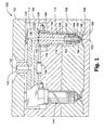
- FIG. 1 is a cross-sectional view of an injection molding apparatus according to an embodiment of the present invention.
- FIG. 2 is a cross-sectional close-up view of the injection molding apparatus in the vicinity of the seal.
- FIG. 3 is a free-body diagram of the seal.
- FIG. 4 is a hidden-line perspective view of the seal.
- FIGS. 5a-d are cross-sectional views of seals according to other embodiments of the present invention.
- FIG. 6 is a cross-sectional view of a compound seal according to another embodiment of the present invention.
- FIG. 1 shows an injection molding apparatus 100 according to an embodiment of the present invention.
- the features and aspects described for the other embodiments can be used accordingly with the present embodiment.
- the injection molding apparatus includes a backing plate 102, a mold plate 104, a cavity plate 106, a core plate 108, an inlet component 110, a manifold 112, and a plurality of nozzles 114.
- the injection molding apparatus 100 may include any number of manifolds and nozzles, in any configuration. In this embodiment, one manifold is shown for simplicity.
- the injection molding apparatus 100 may include additional components, such as plates, alignment dowels, mold gate inserts, and cooling channels, among others.
- the backing plate 102 partially defines an air space 116 and has a central opening that accommodates the inlet component 110.
- the mold plate 104 has a pocket that further defines the air space 116 for accommodating the manifold 112 and partially defines wells 118 for accommodating the nozzles 114.
- the cavity plate 106 further defines the wells 118, partially defines mold cavities 120, and defines mold gates 122 leading into the mold cavities 120.
- Bolts (not shown) are generally used to sandwich the plates together.
- backing plate 102, mold plate 104, and cavity plate 106 and the shapes and sizes of these plates may be varied. The particular number of plates used is not significant, and more or fewer plates than shown may be used.
- the core plate 108 further defines mold cavities 120, in which injection molded products are formed.
- the core plate 108 can be separated from the cavity plate 106 to eject such products.
- the design of the core plate 108 may be varied.
- the inlet component 110 includes an inlet channel 124 for receiving molding material (e.g., plastic melt) from a source, such as a plasticizing screw of an injection molding machine (not shown).
- molding material e.g., plastic melt
- the manifold 112 (upstream runner component) defines a manifold channel 126 (upstream channel) and includes a manifold heater 128.
- the branching manifold channel 126 receives flowing molding material from the inlet channel 124 and distributes the molding material to the nozzles 114.
- the manifold heater 128 can be of any design, such as the embedded insulated resistance wire illustrated.
- the manifold 112 is thermally insulated by the air space 116 defined by the surrounding plates.
- the manifold 112 is offset from the mold plate 104 by the nozzles 114 and a locating ring 130, which also locates the manifold 112 in the correct position.
- the manifold 112 is offset from the backing plate 102 by pressure discs 132, which can elastically deform to absorb differential thermal expansion of the manifold 112 and nozzles 114 with respect to the plates 102, 104.
- the nozzles 114 (downstream runner components) are coupled to the manifold 112 and seated in the wells 118 by the pressure discs 132. Air in the wells 118 serves to insulate the nozzles 114 from the surrounding plates.
- Each nozzle 114 is associated with a mold gate 122 and defines a nozzle channel 134 (downstream channel) in communication with the manifold channel 126 for delivering the flow of molding material to the mold gate 122.
- Each nozzle 114 includes a nozzle body 136, a nozzle flange 138 for supporting the nozzle body 136 in the well 118, a nozzle heater 142 embedded in the nozzle body 136, a thermocouple 144, a terminal end 146 for routing wiring of the heater 142 and thermocouple 144, a nozzle tip 148, and a tip retainer 150 for removably fastening the nozzle tip 148 to the nozzle body 136.
- the nozzle heater 142 can be of any design, such as the embedded insulated resistance wire illustrated.
- the nozzle tip 148 defines a tip channel 152 that forms part of the nozzle channel 134.
- the tip retainer 150 is threaded to the nozzle body 136 and includes a circumferential sealing surface 154 for sealing off the well 118 against backflow of molding material.
- the nozzles 114 in combination with the manifold 112 may be referred to as a hot runner, and generally, an injection molding runner apparatus.
- a seal 160 is provided in the manifold 112 to seal against leakage of molding material at the interface of the manifold 112 and an associated nozzle 114.
- a plurality of such seals 160 can be provided for the plurality of nozzles 114. The seals 160 are discussed in more detail below.
- molding material is injected into the inlet component 110 and flows in a downstream direction through the heated manifold 112 and nozzles 114 to the mold gates 122 and into the mold cavities 120.
- the core plate 108 is withdrawn from the cavity plate 106 and the finished products are ejected, thus completing one cycle of a series.
- FIG. 2 shows a close-up view of the injection molding apparatus 100 in the vicinity of the seal 160.
- the seal 160 is an annular ring having a wedge-shaped profile or cross-section, such as the triangular cross-section depicted.
- the seal 160 is disposed in a like-shaped converging gap defined by the manifold 112 and the nozzle body 136.
- the seal 160 is generally frusto-conical in shape.
- the outer, slanted surface of seal 160 is generally described as a frusto-conical surface 162.
- Seal 160 further includes an annular flat surface 164. Frusto-conical surface 162 and flat surface 164 are configured to be wedged into the converging gap.
- the frusto-conical surface 162 of the seal 160 mates with a frusto-conical surface formed in the manifold 112.
- the flat surface 164 of the seal 160 mates with a flat surface of the nozzle body 136. When viewed in cross-section, the frusto-conical surface 162 and the flat surface 164 appear as straight converging edges of the cross
- the seal 160 defines a seal channel 166 connecting the manifold channel 126 to the nozzle channel 134.
- the seal channel 166 is defined by a cylindrical inside surface 168, which is exposed to molding material.
- pressure of the molding material acts on the cylindrical inside surface 168 to push the frusto-conical surface 162 and the flat surface 164 into sealing contact with the mating surfaces of manifold 112 and nozzle body 136. That is, the pressure acts to wedge the seal 160 into the converging gap.
- FIG. 3 shows a free-body diagram of the seal 160. Pressure arrows are omitted from the right-hand side of the diagram for the sake of clarity.
- a reaction pressure, R1 is exerted by the frusto-conical surface of the manifold 112 on the frusto-conical surface 162 of the seal 160.
- the reaction R1 is generally normal to the surface 162 and thus another reaction pressure, R2, is developed at the flat surface 164 to maintain equilibrium.
- Reactions R1 and R2 are sealing pressures and, generally speaking, the higher their values, the greater the sealing effect of the seal 160.
- the stiffness of the seal 160 contributes to the values of the sealing reactions R1 and R2. All other things being equal, a high stiffness material results in low values for the sealing reactions R1 and R2, while a less stiff material results in higher values. Stiffness is based on geometric and material properties, and the wedge-shaped geometry of the seal 160 has been described. To further increase the sealing effect, the material of the seal 160 can be selected as a low stiffness or more flexible material, such as a material that has a lower stiffness than the surrounding components (i.e., the nozzle body 136 and manifold 112, which are typically made of steel). This is one reason why the seal 160 is a separate piece, and not an integral extension of the nozzle body 136 or manifold 112.
- An appropriate material for seal 160 can be selected to achieve the pressure-assisted sealing described above. Copper, copper alloys, brass, these and other alloys mainly composed of copper, and other relatively soft metals are some examples of suitable materials for some applications. If non-metals are preferred, thermosets, such as silicone rubber, can be used. Polyimide, sold under the names VESPEL and PLAVIS, is also a material that is suitable in some applications. Selecting the specific material used should take into account molding conditions and compatibility with the surrounding materials, including the molding material itself. The preceding materials are exemplary and any material suitable for use in injection molding and conforming to the requirements described herein can be used.
- the shape of the seal 160 aids deformation of the seal 160 into the converging gap.
- the shape of the seal 160 works in conjunction with the material of the seal 160 to provide a pressure-assisted sealing effect that increases as the pressure of the molding material increases. That is, as the pressure of the molding material, P, is increased, the sealing reactions R1 and R2 increase as well.
- An angle, ⁇ that defines the steepness of the frusto-conical shape can be designed, taking into account the selected material of the seal 160, to promote this positive wedging action. Angle ⁇ may be in the range of 20 to 60 degrees.
- FIG. 4 shows a hidden-line perspective view of the seal 160.
- the surfaces 162, 164, 168, are indicated, as well as the through-channel 166.
- FIGS. 5a-d show seals having different geometries according to additional embodiments of the present invention. The features and aspects described for other embodiments, including these embodiments, can be used accordingly with each of these embodiments.
- An upstream runner component 202 and downstream runner component 204 are arranged to deliver molding material.
- the upstream runner component 202 and downstream runner component 204 are coupled together by, for example, mechanical structure (not shown) that holds the upstream runner component 202 and downstream runner component 204 firmly together.
- FIG. 5a shows a seal 206 having a reversed orientation when compared to the seal 160. That is the seal 160 is located in a groove formed in the downstream runner component 204 (e.g., the nozzle). Any of the embodiments described herein can be flipped like this.
- FIG. 5b shows a seal having a concave surface 208 in place of the frusto-conical surface described above.
- the concave surface 208 has double curvature.
- FIG. 5c shows a seal having a slightly convex surface 210 in place of the frusto-conical surface described above.
- the seal is also extended in length to provide a gap 212 between the downstream runner component 204 and upstream runner component 202.
- the convex surface 210 has double curvature but is not hemispherical, meaning that the seal does not act as a ball-joint if the axis 216 of the downstream runner component 204 becomes angularly misaligned from the axis 214 of the upstream runner component 202.
- the non-hemispherical nature of the seal is indicated by the mutually non-tangential extensions of the curves defining the slightly convex surfaces 210, as indicated at 218. Using curvature shallower than hemispherical increases the sealing effect.
- FIG. 5d shows a seal 220 having two frusto-conical surfaces mating with like surfaces in the upstream runner component 202 and downstream runner component 204.
- both reactions R1 and R2 would have components directly resulting from mold pressure P.
- the seal 220 does not extend into the full depth of the converging gap, as indicated at 222.
- the remaining gap 222 results in increased concentration of sealing reactions because the area of the seal 220 for the sealing reactions to act on is reduced.
- the sealing reaction pressures R1 and R2 generally increase as the remaining gap 222 size is increased, with the tradeoff being increased risk of failure of the seal 222 if the remaining gap 222 is made too big, i.e., if the area for reaction pressures R1 and R2 is made too small.
- FIG. 6 shows a compound seal according to another embodiment of the present invention.
- the features and aspects described for the other embodiments can be used accordingly with the present embodiment.
- the upstream runner component 202 and downstream runner component 204 are coupled together by, for example, mechanical structure (not shown) that holds the upstream runner component 202 and downstream runner component 204 firmly together.
- a first, inner wedge seal 240 is disposed in the converging gap, as described in the other embodiments.
- the shape of the first wedge seal 240 is trapezoidal.
- a second, outer wedge seal 242 is disposed deeper in the converging gap and has an inside surface that abuts against an outside surface of the first wedge seal 240 as indicated at 244
- the shape of the second wedge seal 242 is trapezoidal, resulting in part of the converging gap remaining empty, as indicated at 246.
- the second wedge seal 242 is triangular or other shape that fills the remaining gap 246.
- the second wedge seal 242 has a stiffness that is higher than the stiffness of the first wedge seal 240.
- the first wedge seal 240 may be made of copper alloy and the second wedge seal 242 may be made of harder copper alloy or steel.
- the first wedge seal 240 is made of polyimide and the second wedge seal 242 is made of copper.
- the second wedge seal 242 can be made of a material that is less stiff than materials used for the upstream runner component 202 and downstream runner component 204.
- the first and second seals 240, 242 can be connected together (e.g., brazed, adhered, shrink fitted, etc), so that they can be installed and removed as a single piece; or, they may be separate pieces that can easily come apart.
- the second seal 242 may not be required to have material compatibility with the molding material.
- the interplay of the first and second seals 240, 242 can be varied according to molding requirements.
- the first seal 240 can be designed to push against the second seal 242 to transfer some of the sealing demand to the second seal 242 during normal operation.
- the second seal 242 is provided as an emergency backup with no expected sealing duty under normal molding conditions.
- the relative sizes, shapes, and materials of the first and second seals 240, 242 can be selected to achieve any number of variations in performance.
- a finite element analysis (FEA) was carried out on a model similar to the configuration shown in FIG. 2 .
- Sealing stresses i.e., reaction pressures R1 and R2
- reaction pressures R1 and R2 were in the order of 100,000 psi ( ⁇ 689 MPa), which compared favorably to the approximately 22,000 psi ( ⁇ 152 MPa) resulting from a comparable conventional face-to-face seal.
- Maximum deformation at the seal under 35,000 psi ( ⁇ 2,400 bar) pressure of molding material was about 0.0019 inches ( ⁇ 0.048 mm).
- a subsequent, physical test yielded similar results.
- Runner components that can be sealed with the seals described herein include nozzles, manifolds, inlet components, nozzle tips, pipes, tubes, and modular manifold segments, for example.
- the seal may be located at any interface of any two of the aforementioned runner components (e.g., inlet component to manifold interface, nozzle tip to nozzle body interface, main manifold to sub-manifold interface, etc).
- Each runner component may include or not include a heater.
- runner components typically do not include heaters.
Landscapes
- Engineering & Computer Science (AREA)
- General Engineering & Computer Science (AREA)
- Mechanical Engineering (AREA)
- Physics & Mathematics (AREA)
- Fluid Mechanics (AREA)
- Manufacturing & Machinery (AREA)
- Moulds For Moulding Plastics Or The Like (AREA)
- Injection Moulding Of Plastics Or The Like (AREA)
Applications Claiming Priority (1)
| Application Number | Priority Date | Filing Date | Title |
|---|---|---|---|
| US12/434,684 US7874833B2 (en) | 2009-05-03 | 2009-05-03 | Injection molding runner apparatus having pressure seal |
Publications (1)
| Publication Number | Publication Date |
|---|---|
| EP2248652A1 true EP2248652A1 (fr) | 2010-11-10 |
Family
ID=42359419
Family Applications (1)
| Application Number | Title | Priority Date | Filing Date |
|---|---|---|---|
| EP10004534A Withdrawn EP2248652A1 (fr) | 2009-05-03 | 2010-04-29 | Appareil de canal de moulage par injection doté d'un joint d'étanchéité |
Country Status (3)
| Country | Link |
|---|---|
| US (1) | US7874833B2 (fr) |
| EP (1) | EP2248652A1 (fr) |
| CN (1) | CN101875226B (fr) |
Families Citing this family (9)
| Publication number | Priority date | Publication date | Assignee | Title |
|---|---|---|---|---|
| US8147237B2 (en) * | 2008-05-29 | 2012-04-03 | Husky Injection Molding Systems Ltd. | Hot runner system having active material |
| CN102672894B (zh) * | 2012-04-28 | 2015-04-29 | 深圳创维精密科技有限公司 | 热流道系统的热嘴安装结构 |
| US9186830B2 (en) | 2013-12-11 | 2015-11-17 | Mold-Masters (2007) Limited | Drop-in hot runner system |
| CN104632742A (zh) * | 2014-12-18 | 2015-05-20 | 高雅 | 一种直动式减压阀 |
| US11320050B2 (en) * | 2018-02-23 | 2022-05-03 | Nippon Pillar Packing Co., Ltd. | Structure for mounting gasket on block |
| JP7402978B2 (ja) * | 2019-11-12 | 2023-12-21 | シーメンス・ヘルスケア・ダイアグノスティックス・インコーポレイテッド | 液体容器とマニホルドとの間の改良された封止部を含むシステム |
| CN112223678A (zh) * | 2020-10-16 | 2021-01-15 | 苏州煊凯智能科技有限公司 | 一种自动化花盆加工装置 |
| CN114589885B (zh) * | 2022-03-08 | 2023-12-12 | 依润特工业智能科技(苏州)有限公司 | 一种挤出热流道系统 |
| GB202311603D0 (en) * | 2023-07-27 | 2023-09-13 | Baker Hughes Energy Technology UK Ltd | Flexible pipe sealing |
Citations (12)
| Publication number | Priority date | Publication date | Assignee | Title |
|---|---|---|---|---|
| GB273344A (en) * | 1926-06-28 | 1927-12-08 | Karl Peter May | Improvements in pipe joints |
| US2301097A (en) * | 1941-03-08 | 1942-11-03 | Vickers Inc | Power transmission |
| US2933334A (en) * | 1956-01-18 | 1960-04-19 | Moude Adrian J De | Self-sealing pipe coupling |
| US3078110A (en) * | 1958-10-13 | 1963-02-19 | Accessory Products Co | Sealing device |
| US3302953A (en) * | 1963-02-25 | 1967-02-07 | Clarence O Glasgow | Gasket ring and conduit coupling |
| US3339950A (en) * | 1965-04-01 | 1967-09-05 | M & J Valve Co | Coupling devices |
| US3561793A (en) * | 1969-09-03 | 1971-02-09 | Temper Corp | Seal element and spacer member for use therewith |
| WO1990007627A1 (fr) * | 1988-12-27 | 1990-07-12 | Cmf International A/S | Systeme et procede servant a etablir un raccord scelle entre deux extremites de tubes en about |
| US5176409A (en) * | 1989-11-11 | 1993-01-05 | Dixie Iron Works | High pressure pipe coupling |
| WO2001084022A1 (fr) * | 2000-04-20 | 2001-11-08 | Busak + Shamban Gmbh | Dispositif d'etancheification |
| WO2003009986A1 (fr) * | 2001-07-24 | 2003-02-06 | Husky Injection Molding Systems Ltd. | Element d'etancheite dans une machine a mouler par injection |
| EP1300232A1 (fr) * | 2001-10-04 | 2003-04-09 | Quaser S.r.L | Combinaison canal chaud / buse de moulage pour des moules d'injection de matière plastique |
Family Cites Families (67)
| Publication number | Priority date | Publication date | Assignee | Title |
|---|---|---|---|---|
| US3078100A (en) * | 1960-02-25 | 1963-02-19 | Krober Klaus | Tone arm for phonographs |
| US3553788A (en) * | 1968-09-10 | 1971-01-12 | Ladislao Wladyslaw Putkowski | Hot runner system for plastic injection molds |
| DE1929363C3 (de) | 1969-06-10 | 1973-09-13 | Chemische Werke Huels Ag, 4370 Marl | Schaumspritzgußmaschine |
| US3812228A (en) * | 1969-07-17 | 1974-05-21 | Shell Oil Co | Injection molding of foamable thermoplastic polymers using a retractable hot runner |
| CA976314A (en) * | 1972-11-21 | 1975-10-21 | Jobst U. Gellert | Hot runner heater |
| CA1032317A (fr) * | 1975-04-10 | 1978-06-06 | Jobst U. Gellert | Mecanisme a opercule pour le moulage par injection |
| CA1029162A (fr) * | 1975-04-10 | 1978-04-11 | Jobst U. Gellert | Manchon d'etancheite pour moule d'injection a soupape d'admission |
| US4053271A (en) * | 1976-02-04 | 1977-10-11 | Gellert Jobst U | Valve-gated injection molding mechanism |
| NL7900927A (nl) | 1979-02-06 | 1980-08-08 | Anthonie Van Den Brink | Verwarmingspatroon. |
| US4231578A (en) * | 1979-04-23 | 1980-11-04 | W. S. Shamban & Co. | Seal assembly |
| DD160541A3 (de) * | 1979-12-19 | 1983-09-14 | Schwerin Plastverarb Veb | Heisskanalverteiler |
| US4333629A (en) * | 1980-03-11 | 1982-06-08 | Pepsico, Inc. | Floating manifold for multi-cavity injection mold |
| SE434482B (sv) * | 1981-05-07 | 1984-07-30 | Dante Luigi Alfonsi | Varmkanalsystem vid en maskin for formsprutning av plast |
| DE3211342A1 (de) | 1982-03-27 | 1983-09-29 | Wilhelm 6128 Höchst Volk | Kunststoffspritzpresse mit einer zufuehrvorrichtung zum zufuehren einer thermoplastischen masse |
| CA1193818A (fr) * | 1983-03-24 | 1985-09-24 | Jobst U. Gellert | Systeme de moulage par injection avec commande hydraulique a raccordements alternes |
| DE3338783C1 (de) | 1983-10-26 | 1985-03-21 | Werner & Pfleiderer, 7000 Stuttgart | Spritzgießform zur Herstellung von Formartikeln aus wärmehärtbaren Werkstoffen |
| DE8507696U1 (de) | 1985-03-15 | 1986-10-23 | Günther, Herbert, Dipl.-Ing., 3559 Allendorf | Spritzgießvorrichtung |
| US4662837A (en) * | 1985-03-18 | 1987-05-05 | Husky Injection Molding Systems, Ltd. | Apparatus for injection molding |
| DE3641711A1 (de) | 1986-12-06 | 1988-06-09 | Guenther Herbert | Verteiler |
| US5227179A (en) * | 1988-07-11 | 1993-07-13 | Salvatore Benenati | Assembly of injection molding manifold, nozzles and mold |
| JPH0624181Y2 (ja) | 1990-07-09 | 1994-06-29 | 池上金型工業株式会社 | 射出成形用金型 |
| US5147663A (en) | 1990-10-09 | 1992-09-15 | Panos Trakas | Modular manifold assembly |
| CA2047461A1 (fr) | 1991-07-19 | 1993-01-20 | Jobst Ulrich Gellert | Distributeur de moulage par injection avec insertions amovibles |
| CA2079390C (fr) * | 1991-10-16 | 1996-08-27 | Akira Nonomura | Moule a empreintes multipes, methode de fabrication et commande de remplissage du moule |
| JPH05237879A (ja) | 1992-02-27 | 1993-09-17 | Fuji Photo Film Co Ltd | 射出成形用金型 |
| US6147696A (en) * | 1993-06-24 | 2000-11-14 | Nintendo Co. Ltd. | Electronic entertainment and communication system |
| DE4324027A1 (de) | 1993-07-17 | 1995-01-19 | Goetze Ag | Vorrichtung für Spritzgieß- und Spritzpreßmaschinen |
| CA2115613C (fr) * | 1994-02-14 | 2002-02-12 | Jobst Ulrich Gellert | Machine de moulage pour injection equipee d'un obturateur d'orifice d'admission muni d'une bague d'etancheite a collet flexible |
| DE4404894C1 (de) | 1994-02-16 | 1995-01-05 | Dangelmaier Sfr Formbau | Beheizte Düse zur Zuführung einer Kunststoffschmelze in die Formhöhlung eines Kunststoff-Spritzgießwerkzeuges |
| US5499916A (en) * | 1994-10-28 | 1996-03-19 | Husky Injection Molding Systems Ltd. | Rotary actuated gate valve |
| US5609893A (en) * | 1995-01-12 | 1997-03-11 | Jk Molds, Inc. | Probe assembly for injection molding apparatus |
| DE29501450U1 (de) * | 1995-01-31 | 1995-03-30 | Dipl.-Ing. Herbert Günther Gesellschaft mbH, Perchtoldsdorf | Heißkanaldüse |
| DE19603947C2 (de) | 1996-02-05 | 1999-02-11 | Incoe Inernational Inc | Heißkanal-Verteilersystem für Spritzgießanlagen |
| US5896640A (en) * | 1996-11-12 | 1999-04-27 | Husky Injection Molding Systems Ltd. | Deflection sealing apparatus and method |
| DE19649621B4 (de) * | 1996-11-29 | 2007-08-02 | EWIKON Heißkanalsysteme GmbH & Co KG | Verbindungsanordnung für Schmelzekanalabschnitte in Heißkanälen |
| US5820899A (en) * | 1996-12-23 | 1998-10-13 | Mold-Masters Limited | Injection molding nozzle with edge gate inserts and sealing ring |
| CA2205978C (fr) * | 1997-05-23 | 2005-01-18 | Jobst Ulrich Gellert | Manchon de raccordement de collecteurs de moulage par injection |
| US6062846A (en) | 1997-06-13 | 2000-05-16 | Husky Injection Molding Systems, Ltd. | Injection molding nozzle assembly |
| US6261084B1 (en) * | 1998-08-28 | 2001-07-17 | Synventive Moldings Solutions Canada, Inc. | Elastically deformable nozzle for injection molding |
| CA2262175C (fr) * | 1999-02-16 | 2008-02-12 | Mold-Masters Limited | Materiel de moulage par injection a joint de bec detachable |
| NL1012925C2 (nl) * | 1999-08-27 | 2001-02-28 | Franciscus Antonius Jozef Van | Spuitgietinrichting. |
| JP2001121585A (ja) | 1999-10-29 | 2001-05-08 | Pentel Corp | ホットランナー装置 |
| ITPN20000025A1 (it) | 2000-04-20 | 2001-10-20 | Sipa Spa | Ugello di iniezione di sostanza plastica |
| IT1320639B1 (it) | 2000-09-13 | 2003-12-10 | Piero Enrietti | Testa riscaldata di alimentazione di un ugello di iniezione per lostampaggio di materiali plastici. |
| DE10123314C1 (de) | 2001-05-14 | 2002-07-11 | Sfr Formenbau Gmbh | Einspritzdüse zur Führung von Schmelzemasse in einer Kunststoffspritzgießform od. dgl. |
| JP2003103582A (ja) * | 2001-09-28 | 2003-04-09 | Mitsubishi Materials Corp | 射出成形金型 |
| DE10150419A1 (de) | 2001-10-11 | 2003-05-08 | Wolfgang Zimmermann | Abdichtung von Rohr- und Behälterverbindungen mittels Innendruck auf dünne Ränder |
| CA2474024A1 (fr) * | 2002-02-04 | 2003-08-14 | Mold-Masters Limited | Joint thermosoude entre un collecteur et une buse |
| US7137807B2 (en) * | 2002-11-21 | 2006-11-21 | Mold-Masters Limited | Hot runner nozzle with a tip, a tip surrounding piece and an alignment piece |
| US7189071B2 (en) * | 2003-02-12 | 2007-03-13 | Mold-Masters Limited | Telescopic manifold nozzle seal |
| US7306454B2 (en) * | 2003-04-07 | 2007-12-11 | Mold-Masters Limited | Front-mountable injection molding nozzle |
| CA2441139C (fr) | 2003-09-17 | 2010-11-16 | Mold-Masters Limited | Sertisseuse de collecteur a une buse |
| US20050255189A1 (en) * | 2004-05-17 | 2005-11-17 | Manda Jan M | Method and apparatus for coupling melt conduits in a molding system and/or a runner system |
| FR2876619B1 (fr) | 2004-10-15 | 2007-01-05 | Delachaux Sa Sa | Dispositif d'injection-moulage a etancheite renforcee entre buse d'injection et matrice de moulage |
| FR2877870B1 (fr) | 2004-11-18 | 2007-02-09 | Mecafonction Sarl | Structure a canaux chauds pour moule d'injection |
| CA2542374A1 (fr) * | 2005-04-07 | 2006-10-07 | Mold-Masters Limited | Distributeur configurable |
| KR100746555B1 (ko) | 2005-11-04 | 2007-08-09 | 허남욱 | 플라스틱제품 성형용 열팽창 완충 확장메니폴드 |
| US7445444B2 (en) * | 2006-01-26 | 2008-11-04 | Mold-Masters (2007) Limited | Insert for an injection molding apparatus |
| DE102006004265A1 (de) * | 2006-01-31 | 2007-08-09 | Incoe International, Inc. | Hochbelastbare Dichtungen für Spritzgießanlagen |
| US7462032B2 (en) * | 2006-06-15 | 2008-12-09 | Husky Injection Molding Systems Ltd. | Split sprue bar having a device for preventing leakage |
| US20080035297A1 (en) * | 2006-08-11 | 2008-02-14 | Husky Injection Molding Systems Ltd. | Seal of a metal molding system |
| US20080089969A1 (en) * | 2006-10-12 | 2008-04-17 | Husky Injection Molding Systems Ltd. | Barrel head of extruder of molding system, barrel head having outer and inner portions, amongst other things |
| US7575428B2 (en) * | 2006-10-12 | 2009-08-18 | Husky Injection Molding Systems Ltd. | Molding system including body overlapping and sealing conduits, amongst other things |
| US7517208B2 (en) * | 2006-10-12 | 2009-04-14 | Husky Injection Molding Systems Ltd. | Injection molding system having a cooperating tapered machine nozzle and barrel head |
| US7467940B2 (en) * | 2006-10-20 | 2008-12-23 | Husky Injection Molding Systems Ltd. | System and Method for Joining Non-Compatible Components |
| US20080181983A1 (en) * | 2007-01-31 | 2008-07-31 | Haque Zakiul | Injection Molding Nozzle |
| US7614871B2 (en) * | 2007-07-12 | 2009-11-10 | Husky Injection Molding Systems Ltd | Rotary valve assembly for an injection nozzle |
-
2009
- 2009-05-03 US US12/434,684 patent/US7874833B2/en not_active Expired - Fee Related
-
2010
- 2010-04-29 EP EP10004534A patent/EP2248652A1/fr not_active Withdrawn
- 2010-05-04 CN CN201010178130.6A patent/CN101875226B/zh not_active Expired - Fee Related
Patent Citations (14)
| Publication number | Priority date | Publication date | Assignee | Title |
|---|---|---|---|---|
| GB273344A (en) * | 1926-06-28 | 1927-12-08 | Karl Peter May | Improvements in pipe joints |
| US2301097A (en) * | 1941-03-08 | 1942-11-03 | Vickers Inc | Power transmission |
| US2933334A (en) * | 1956-01-18 | 1960-04-19 | Moude Adrian J De | Self-sealing pipe coupling |
| US3078110A (en) * | 1958-10-13 | 1963-02-19 | Accessory Products Co | Sealing device |
| US3302953A (en) * | 1963-02-25 | 1967-02-07 | Clarence O Glasgow | Gasket ring and conduit coupling |
| US3339950A (en) * | 1965-04-01 | 1967-09-05 | M & J Valve Co | Coupling devices |
| US3561793A (en) * | 1969-09-03 | 1971-02-09 | Temper Corp | Seal element and spacer member for use therewith |
| WO1990007627A1 (fr) * | 1988-12-27 | 1990-07-12 | Cmf International A/S | Systeme et procede servant a etablir un raccord scelle entre deux extremites de tubes en about |
| US5176409A (en) * | 1989-11-11 | 1993-01-05 | Dixie Iron Works | High pressure pipe coupling |
| WO2001084022A1 (fr) * | 2000-04-20 | 2001-11-08 | Busak + Shamban Gmbh | Dispositif d'etancheification |
| WO2003009986A1 (fr) * | 2001-07-24 | 2003-02-06 | Husky Injection Molding Systems Ltd. | Element d'etancheite dans une machine a mouler par injection |
| US6561790B2 (en) | 2001-07-24 | 2003-05-13 | Husky Injection Molding Systems, Ltd. | Sealing member in an injection molding machine |
| EP1300232A1 (fr) * | 2001-10-04 | 2003-04-09 | Quaser S.r.L | Combinaison canal chaud / buse de moulage pour des moules d'injection de matière plastique |
| US20030075563A1 (en) | 2001-10-04 | 2003-04-24 | Quaser S.R.I., Italian Nationality | Hot runner - injector nozzle assembly for plastic material injection molds |
Non-Patent Citations (1)
| Title |
|---|
| W. BEITZ , K.-H. KÜTTNER: "Dubble, Taschenbuch für den Maschinenbau", vol. 17, 1990, SPRINGER-VERLAG, Berlin, ISBN: 3-540-52381-2, pages: K18 - 2.10.1, XP002596079 * |
Also Published As
| Publication number | Publication date |
|---|---|
| CN101875226A (zh) | 2010-11-03 |
| CN101875226B (zh) | 2013-06-19 |
| US20100278962A1 (en) | 2010-11-04 |
| US7874833B2 (en) | 2011-01-25 |
Similar Documents
| Publication | Publication Date | Title |
|---|---|---|
| US7874833B2 (en) | Injection molding runner apparatus having pressure seal | |
| US7918663B2 (en) | Injection molding nozzle wedge seal | |
| US7794228B2 (en) | Injection molding apparatus having an edge-gated runnerless nozzle | |
| EP2839942B1 (fr) | Agencement de joint de buse pour un appareil de moulage par injection | |
| US6860732B2 (en) | Thermal seal between manifold and nozzle | |
| US7549855B2 (en) | Nozzle tip for high melt pressure applications | |
| US7244118B2 (en) | Hot runner nozzle and manifold seal | |
| EP1475210B1 (fr) | Buse d'injection à canal chaud avec tête et élément de retenue de tête amovible et procédé pour produire une buse d'injection à canal chaud | |
| EP1475211B1 (fr) | Joint amovible pour une tête d'injection dans une presse à injecter | |
| CN106945234B (zh) | 注塑成型喷嘴用嵌件以及具有所述嵌件的注塑成型喷嘴 | |
| KR101895036B1 (ko) | 히트 스프레더 일체형 핫 런너 시스템 | |
| JP7826016B2 (ja) | 装置、金型、射出成形機、製造ユニット、樹脂成形品の製造方法 | |
| WO2000023244A1 (fr) | Appareil a buse de moulage par injection | |
| HK1236894A1 (en) | Insert for an injection-moulding nozzle and injection-moulding nozzle having such an insert |
Legal Events
| Date | Code | Title | Description |
|---|---|---|---|
| PUAI | Public reference made under article 153(3) epc to a published international application that has entered the european phase |
Free format text: ORIGINAL CODE: 0009012 |
|
| AK | Designated contracting states |
Kind code of ref document: A1 Designated state(s): AT BE BG CH CY CZ DE DK EE ES FI FR GB GR HR HU IE IS IT LI LT LU LV MC MK MT NL NO PL PT RO SE SI SK SM TR |
|
| AX | Request for extension of the european patent |
Extension state: AL BA ME RS |
|
| 17P | Request for examination filed |
Effective date: 20110509 |
|
| 17Q | First examination report despatched |
Effective date: 20120829 |
|
| STAA | Information on the status of an ep patent application or granted ep patent |
Free format text: STATUS: THE APPLICATION HAS BEEN WITHDRAWN |
|
| 18W | Application withdrawn |
Effective date: 20130308 |