EP2252071A2 - Conversion d'images améliorée et techniques de codage - Google Patents
Conversion d'images améliorée et techniques de codage Download PDFInfo
- Publication number
- EP2252071A2 EP2252071A2 EP10173075A EP10173075A EP2252071A2 EP 2252071 A2 EP2252071 A2 EP 2252071A2 EP 10173075 A EP10173075 A EP 10173075A EP 10173075 A EP10173075 A EP 10173075A EP 2252071 A2 EP2252071 A2 EP 2252071A2
- Authority
- EP
- European Patent Office
- Prior art keywords
- depth
- depth map
- data
- map
- allocating
- Prior art date
- Legal status (The legal status is an assumption and is not a legal conclusion. Google has not performed a legal analysis and makes no representation as to the accuracy of the status listed.)
- Withdrawn
Links
Images





Classifications
-
- G—PHYSICS
- G06—COMPUTING OR CALCULATING; COUNTING
- G06T—IMAGE DATA PROCESSING OR GENERATION, IN GENERAL
- G06T7/00—Image analysis
- G06T7/40—Analysis of texture
-
- G—PHYSICS
- G06—COMPUTING OR CALCULATING; COUNTING
- G06T—IMAGE DATA PROCESSING OR GENERATION, IN GENERAL
- G06T9/00—Image coding
- G06T9/001—Model-based coding, e.g. wire frame
-
- G—PHYSICS
- G06—COMPUTING OR CALCULATING; COUNTING
- G06T—IMAGE DATA PROCESSING OR GENERATION, IN GENERAL
- G06T7/00—Image analysis
- G06T7/10—Segmentation; Edge detection
- G06T7/12—Edge-based segmentation
-
- G—PHYSICS
- G06—COMPUTING OR CALCULATING; COUNTING
- G06T—IMAGE DATA PROCESSING OR GENERATION, IN GENERAL
- G06T7/00—Image analysis
- G06T7/50—Depth or shape recovery
- G06T7/55—Depth or shape recovery from multiple images
- G06T7/593—Depth or shape recovery from multiple images from stereo images
-
- G—PHYSICS
- G06—COMPUTING OR CALCULATING; COUNTING
- G06T—IMAGE DATA PROCESSING OR GENERATION, IN GENERAL
- G06T7/00—Image analysis
- G06T7/97—Determining parameters from multiple pictures
-
- H—ELECTRICITY
- H04—ELECTRIC COMMUNICATION TECHNIQUE
- H04N—PICTORIAL COMMUNICATION, e.g. TELEVISION
- H04N13/00—Stereoscopic video systems; Multi-view video systems; Details thereof
- H04N13/10—Processing, recording or transmission of stereoscopic or multi-view image signals
- H04N13/106—Processing image signals
- H04N13/167—Synchronising or controlling image signals
-
- H—ELECTRICITY
- H04—ELECTRIC COMMUNICATION TECHNIQUE
- H04N—PICTORIAL COMMUNICATION, e.g. TELEVISION
- H04N13/00—Stereoscopic video systems; Multi-view video systems; Details thereof
- H04N13/20—Image signal generators
- H04N13/204—Image signal generators using stereoscopic image cameras
- H04N13/207—Image signal generators using stereoscopic image cameras using a single two-dimensional [2D] image sensor
- H04N13/221—Image signal generators using stereoscopic image cameras using a single two-dimensional [2D] image sensor using the relative movement between cameras and objects
-
- H—ELECTRICITY
- H04—ELECTRIC COMMUNICATION TECHNIQUE
- H04N—PICTORIAL COMMUNICATION, e.g. TELEVISION
- H04N13/00—Stereoscopic video systems; Multi-view video systems; Details thereof
- H04N13/20—Image signal generators
- H04N13/261—Image signal generators with monoscopic-to-stereoscopic image conversion
-
- H—ELECTRICITY
- H04—ELECTRIC COMMUNICATION TECHNIQUE
- H04N—PICTORIAL COMMUNICATION, e.g. TELEVISION
- H04N19/00—Methods or arrangements for coding, decoding, compressing or decompressing digital video signals
- H04N19/50—Methods or arrangements for coding, decoding, compressing or decompressing digital video signals using predictive coding
- H04N19/597—Methods or arrangements for coding, decoding, compressing or decompressing digital video signals using predictive coding specially adapted for multi-view video sequence encoding
-
- G—PHYSICS
- G06—COMPUTING OR CALCULATING; COUNTING
- G06T—IMAGE DATA PROCESSING OR GENERATION, IN GENERAL
- G06T2207/00—Indexing scheme for image analysis or image enhancement
- G06T2207/10—Image acquisition modality
- G06T2207/10004—Still image; Photographic image
- G06T2207/10012—Stereo images
-
- H—ELECTRICITY
- H04—ELECTRIC COMMUNICATION TECHNIQUE
- H04N—PICTORIAL COMMUNICATION, e.g. TELEVISION
- H04N13/00—Stereoscopic video systems; Multi-view video systems; Details thereof
- H04N13/10—Processing, recording or transmission of stereoscopic or multi-view image signals
- H04N13/106—Processing image signals
- H04N13/15—Processing image signals for colour aspects of image signals
-
- H—ELECTRICITY
- H04—ELECTRIC COMMUNICATION TECHNIQUE
- H04N—PICTORIAL COMMUNICATION, e.g. TELEVISION
- H04N13/00—Stereoscopic video systems; Multi-view video systems; Details thereof
- H04N13/10—Processing, recording or transmission of stereoscopic or multi-view image signals
- H04N13/106—Processing image signals
- H04N13/161—Encoding, multiplexing or demultiplexing different image signal components
-
- H—ELECTRICITY
- H04—ELECTRIC COMMUNICATION TECHNIQUE
- H04N—PICTORIAL COMMUNICATION, e.g. TELEVISION
- H04N13/00—Stereoscopic video systems; Multi-view video systems; Details thereof
- H04N13/10—Processing, recording or transmission of stereoscopic or multi-view image signals
- H04N13/189—Recording image signals; Reproducing recorded image signals
-
- H—ELECTRICITY
- H04—ELECTRIC COMMUNICATION TECHNIQUE
- H04N—PICTORIAL COMMUNICATION, e.g. TELEVISION
- H04N13/00—Stereoscopic video systems; Multi-view video systems; Details thereof
- H04N13/10—Processing, recording or transmission of stereoscopic or multi-view image signals
- H04N13/194—Transmission of image signals
-
- H—ELECTRICITY
- H04—ELECTRIC COMMUNICATION TECHNIQUE
- H04N—PICTORIAL COMMUNICATION, e.g. TELEVISION
- H04N13/00—Stereoscopic video systems; Multi-view video systems; Details thereof
- H04N13/20—Image signal generators
- H04N13/204—Image signal generators using stereoscopic image cameras
- H04N13/239—Image signal generators using stereoscopic image cameras using two two-dimensional [2D] image sensors having a relative position equal to or related to the interocular distance
-
- H—ELECTRICITY
- H04—ELECTRIC COMMUNICATION TECHNIQUE
- H04N—PICTORIAL COMMUNICATION, e.g. TELEVISION
- H04N13/00—Stereoscopic video systems; Multi-view video systems; Details thereof
- H04N13/20—Image signal generators
- H04N13/204—Image signal generators using stereoscopic image cameras
- H04N13/243—Image signal generators using stereoscopic image cameras using three or more two-dimensional [2D] image sensors
-
- H—ELECTRICITY
- H04—ELECTRIC COMMUNICATION TECHNIQUE
- H04N—PICTORIAL COMMUNICATION, e.g. TELEVISION
- H04N13/00—Stereoscopic video systems; Multi-view video systems; Details thereof
- H04N13/20—Image signal generators
- H04N13/257—Colour aspects
-
- H—ELECTRICITY
- H04—ELECTRIC COMMUNICATION TECHNIQUE
- H04N—PICTORIAL COMMUNICATION, e.g. TELEVISION
- H04N13/00—Stereoscopic video systems; Multi-view video systems; Details thereof
- H04N13/20—Image signal generators
- H04N13/296—Synchronisation thereof; Control thereof
-
- H—ELECTRICITY
- H04—ELECTRIC COMMUNICATION TECHNIQUE
- H04N—PICTORIAL COMMUNICATION, e.g. TELEVISION
- H04N13/00—Stereoscopic video systems; Multi-view video systems; Details thereof
- H04N13/30—Image reproducers
- H04N13/332—Displays for viewing with the aid of special glasses or head-mounted displays [HMD]
- H04N13/341—Displays for viewing with the aid of special glasses or head-mounted displays [HMD] using temporal multiplexing
-
- H—ELECTRICITY
- H04—ELECTRIC COMMUNICATION TECHNIQUE
- H04N—PICTORIAL COMMUNICATION, e.g. TELEVISION
- H04N13/00—Stereoscopic video systems; Multi-view video systems; Details thereof
- H04N13/30—Image reproducers
- H04N13/398—Synchronisation thereof; Control thereof
-
- H—ELECTRICITY
- H04—ELECTRIC COMMUNICATION TECHNIQUE
- H04N—PICTORIAL COMMUNICATION, e.g. TELEVISION
- H04N13/00—Stereoscopic video systems; Multi-view video systems; Details thereof
- H04N2013/0074—Stereoscopic image analysis
- H04N2013/0077—Colour aspects
-
- H—ELECTRICITY
- H04—ELECTRIC COMMUNICATION TECHNIQUE
- H04N—PICTORIAL COMMUNICATION, e.g. TELEVISION
- H04N13/00—Stereoscopic video systems; Multi-view video systems; Details thereof
- H04N2013/0074—Stereoscopic image analysis
- H04N2013/0081—Depth or disparity estimation from stereoscopic image signals
-
- H—ELECTRICITY
- H04—ELECTRIC COMMUNICATION TECHNIQUE
- H04N—PICTORIAL COMMUNICATION, e.g. TELEVISION
- H04N13/00—Stereoscopic video systems; Multi-view video systems; Details thereof
- H04N2013/0074—Stereoscopic image analysis
- H04N2013/0085—Motion estimation from stereoscopic image signals
-
- H—ELECTRICITY
- H04—ELECTRIC COMMUNICATION TECHNIQUE
- H04N—PICTORIAL COMMUNICATION, e.g. TELEVISION
- H04N13/00—Stereoscopic video systems; Multi-view video systems; Details thereof
- H04N2013/0074—Stereoscopic image analysis
- H04N2013/0092—Image segmentation from stereoscopic image signals
Definitions
- the present invention is generally directed towards stereoscopic image synthesis and more particularly toward an improved method of converting two dimensional (2D) images for further encoding, transmission and decoding for the purpose of stereoscopic image display.
- 2D two dimensional
- the present invention further improves the operation of the Applicant's earlier system.
- a method of encoding a depth map comprising:
- the object outline may be defined by a series of co-ordinates, curves and/or, geometric shapes.
- Said identifying tag may be a unique numerical number.
- Identifying said at least one object may include the step of comparing said 2D image with a library of generic scenes.
- the step of determining the outline may further include one of:
- the depth tag may include a colour code.
- white may represent objects relatively close to the viewer, and black may indicate objects relatively distant from the viewer.
- said depth tag may be a numerical value.
- said numerical value may range from 0 to 255.
- Said at least one object may be further divided into a plurality of segments, each segment being assigned a depth tag.
- the variation in depth may be defined by a ramp function.
- Said ramp function may be a linear or radial ramp.
- the method may further include tracking the or each object on successive frames of the image, and determining and assigning depth tags for the object in each respective frame.
- the method may further include adding a texture bump map to the or each object.
- said texture bump map may be defined by one of:
- the method may further include producing greyscale images of 80x60x8 bit resolution of each 2D image.
- the method may further include the step of adding security measures to the sequence prior to said video sequence being divided into a plurality of partial sequences.
- Said security measures may include removing audio from and/or modifying the colours of the video sequence.
- Said object outline may be defined by a series of x,y coordinates, each x,y coordinate being separated by a curve.
- each x,y coordinate being separated by a curve.
- Said object outline may be defined by at least one geometric shape.
- Said at least one geometric shape may be defined by the form of the shape and the parameters of the shape.
- the encoding of the depth tag of said object may include:
- the type of depth may include single value, linear ramp, or radial ramp.
- the method may further include:
- Objects in the 2D image to be converted may be identified by a human operator using visual inspection.
- the operator will typically tag each object, or group of objects, in the image using a computer mouse, light pen, stylus or other device and assign a unique number to the object.
- the number may be manually created by the operator or automatically generated in a particular sequence by a computer.
- Objects may also be identified fully automatically using a computer or semi-automatically whereby an operator assists the computer to determine the location of an object(s).
- Neural networks and expert systems may also be used to assist with identifying objects.
- an operator may provide assistance to the computer by advising the computer as to the nature of the image where objects may be found. For example the operator may advise the computer that the scene is of the generic format "News Reader” in which case the computer will attempt to locate the head and shoulders of the news reader, desk and background etc. The operator may choose from a menu of possible generic scenes. The operator may manually override and/or correct and adjust any object selection made by the computer. The computer program may learn from these corrections, using neural networks or expert systems for example, so as to continually improve the accuracy of object identification and numbering.
- the object may then be tracked either manually, automatically or semi-automatically as it moves within the image over successive frames.
- An operator may also use object identification information produced by another operator either working on the same sequence or from prior conversion of similar scenes.
- the outline of an object or objects may be determined either manually, automatically or semi-automatically.
- the operator may trace the outline of the object or objects using a computer mouse, light pen, stylus or other device.
- the operator may select the outline of the object on a pixel by pixel basis, use straight line or curve approximations, bezier curves or best fit from a library of curves or generic shapes.
- the operator may also choose from a library of generic shapes which may already be of approximately the correct shape and scale or adjust the shape dynamically to fit. For example the operator may wish to select the outline of a man in which case the generic outline of a man may be retrieved from the library and adjusted accordingly, either manually, semi-automatically or automatically.
- the operator may also select from a library of geometric shapes such as circles, ellipses, triangles, squares etc.
- the computer may use such characteristics as size, colour, speed of motion, shading, brightness, obscuration, differences between previous and current and future images.
- Neural networks and expert systems may also be used to determine the outline of objects.
- an operator may provide assistance to the computer by advising the computer as to the nature of the image where objects may be found. For example the operator may advise the computer that the scene is of the generic format "News Reader” in which case the computer will attempt to locate the head and shoulders of the news reader, desk and background etc. The operator may choose from a menu of possible generic objects. The operator may manually override and/or correct and adjust any object outlining made by the computer. The computer program may learn from these corrections, using neural networks or expert systems for example, so as to continually improve the accuracy of outlining.
- the object may then be tracked either manually, automatically or semi-automatically as it moves within the image over successive frames.
- An operator may also use object outline information produced by another operator either working on the same sequence or from prior conversion of similar scenes.
- the operator may also choose from a library of predefined outlines, which may include geometric shapes such as circles, ellipses, triangles, squares etc, and either manually, semi-automatically or automatically adjust the library outline to fit the selected object.
- the library may be indexed by individual outlines e.g. News Reader or based upon a particular family of objects e.g. Horse Race, Evening News etc.
- the depth of an object or objects may be determined either manually, automatically or semi-automatically.
- the depth of the objects may be assigned using any alphanumeric, visual, audible or tactile information.
- the depth of the object is indicated by shading the object with a particular colour. Typically this will be white for objects that are to appear, once converted, at a 3D position closest to the viewer and black for objects that are at the furthest 3D distance from the viewer. Obviously this convention may be altered, e.g. reversed or colours used to indicate relative or absolute depth.
- the depth of the object may be assigned a numerical value.
- This value may be positive or negative, in a linear or nonlinear series and contain single or multiple digits. In a preferred embodiment this value will range from 0 to 255, to enable the value to be encoded in a single byte, where 255 represents objects that are to appear, once converted, at a 3D position closest to the viewer and 0 for objects that are at the furthest 3D distance from the viewer. Obviously this convention may be altered, e.g. reversed or another range used.
- the operator may assign the depth of the object or objects using a computer mouse, light pen, stylus or other device.
- the operator may assign the depth of the object by placing the pointing device within the object outline and entering a depth value.
- the depth may be entered by the operator as a numeric, alphanumeric or graphical value and may be assigned by the operator or automatically assigned by the computer from a predetermined range of allowable values.
- the operator may also select the object depth from a library or menu of allowable depths.
- the operator may also assign a range of depths within an object or a depth range that varies with time, object location or motion or any combination of these factors.
- the object may be a table that has its closest edge towards the viewer and its farthest edge away from the viewer. When converted into 3D the apparent depth of the table must vary along its length. In order to achieve this the operator may divide the table up into a number of segments and assign each segment an individual depth. Alternatively the operator may assign a continuously variable depth within the object by shading the object such that the amount of shading represents the depth at that particular position of the table. In this example a light shading could represent a close object and dark shading a distant object. For the example of the table, the closest edge would be shaded lightly, with the shading getting progressively darker, until the furthest edge is reached.
- the variation of depth within an object may be linear or non-linear and may vary with time, object location or motion or any combination of these factors.
- the variation of depth within an object may be in the form of a ramp.
- a linear ramp would have a start point (A) and an end point (B).
- the colour at point A and B is defined.
- a gradient from Point A to Point B is applied on the perpendicular line.
- a Radial Ramp defines a similar ramp to a linear ramp although it uses the distance from a centre point (A) to a radius (B).
- a simple extension to the Radial Ramp would be to taper the outside rim, or to allow a variable sized centre point.
- a Linear Extension is the distance from a line segment as opposed to the distance from the perpendicular.
- the colour is defined for the line segment, and the colour for the "outside”.
- the colour along the line segment is defined, and the colour tapers out to the "outside” colour.
- Ramps can be easily encoded. Ramps may also be based on more complex curves, equations, variable transparency etc.
- an object may move from the front of the image to the rear over a period of frames.
- the operator could assign a depth for the object in the first frame and depth of the object in the last or subsequent scene.
- the computer may then interpolate the depth of the object over successive frames in a linear or other predetermined manner. This process may also be fully automated whereby a computer assigns the variation in object depth based upon the change in size of an object as it moves over time.
- automatic depth defining the computer may use such characteristics as size, colour, speed of motion, shading, brightness, obscuration, focus, differences between previous and current and future images.
- Neural networks and expert systems may also be used to determine the depth of objects.
- an operator may provide assistance to the computer by advising the computer as to the nature of the image where depths are to be assigned. For example the operator may advise the computer that the scene is of the generic format "News Reader” in which case the computer will attempt to locate the head and shoulders of the news reader, desk and background etc and place these in a logical depth sequence.
- the operator may choose from a menu of possible generic objects and depths. The operator may manually override and/or correct and adjust any object depth decision made by the computer.
- the computer program may learn from these corrections, using neural networks or expert systems for example, so as to continually improve the accuracy of depth assigning.
- the object may then be tracked either manually, automatically or semi-automatically as it moves within the image over successive frames.
- An operator may also use depth definitions produced by another operator either working on the same sequence or from prior conversion of similar scenes.
- depth definitions that are more complex than simple ramps or linear variations.
- the depth map for such objects could be produced by adding a texture bump map to the object. For example, if we consider a tree, the first step would be to trace around the outline of the tree and then assign the tree a depth. Then a texture bump map could be added to give each leaf on the tree its own individual depth.
- texture maps have been found useful to the present invention for adding detail to relatively simple objects.
- a further and more preferred method is to use the luminance (or black and white components) of the original object to create the necessary bump map.
- elements of the object that are closer to the viewer will be lighter and those further away darker.
- a bump map can be automatically created.
- the advantage of this technique is that the object itself can be used to create its own bump map and any movement of the object from frame to frame is automatically tracked.
- Other attributes of an object may also be used to create a bump map, these include but are not limited to, chrominance, saturation, colour grouping, reflections, shadows, focus, sharpness etc.
- the bump map values obtained from object attributes will also preferably be scaled so that the range of depth variation within the object are consistent with the general range of depths of the overall image.
- Depth Maps The process of detecting objects, determining their outline and assigning depths we will refer to as the creation of Depth Maps.
- the depth maps would consist of grayscale images of 80x60x8bit resolution to enable the objects within the associated 2D image to be defined at one of 256 individual depths.
- the shape of the curve can be defined as a ratio of the distance between the sequential xy coordinates and the displacement of the curve from a straight line between these points.
- x1y1 and x2y2 located on a line A and being joined by a curve.
- the curve between these points has a maximum displacement B measured from the line A to the midpoint of the curve.
- the depth maps may be encoded in a number of ways.
- the object number, depth and object outline are encoded as follows. Consider the outline of a person shown in figure 3 . The person is allocated object number 1 with depth 20. The outline of the object has been determined as previously explained and at specific x, y locations. Typically where a change in direction of the object outline takes place, a particular mark is made. This mark may be an alphanumeric character, a shape, colour or other form of visual indication. Each of these marks will have a specific x, y location. In the preferred embodiment this will be within the range 0 to 255. Between each pair of x, y locations will exist a curve. Each curve may be determined by selection from a library of all possible curve shapes.
- each curve will be given a value typically within the range -127 to +128 to enable the curve to be defined using one byte. Curves that progress clockwise from x, y location to the next x, y location may be assigned positive values whilst those that progress anticlockwise may be assigned negative values. Other assignments may be applied.
- Adding a depth threshold to the conversion algorithm ensures that objects in front of the threshold are not distorted. This is done to prevent some of the minor distortions that occur at the edges of foreground objects when they intersect with a background object.
- a depth map is used to create a continuous depth map that forms the 3D profile of the final scene.
- a threshold is applied to this process the depth map is processed to detect threshold transitions, and depth above and below the transition are processed independently.
- the depth map data for this object may therefore be defined as follows: ⁇ object number > ⁇ object depth > ⁇ x1 ,y1, curve1, x2,y2, curve2 ... x1 ,y1 >
- the object depth information contains the data required to generate the depth of the current object.
- this depth data may be a single value, a ramp (linear, radial or other), or other method of describing the depth of a single object.
- the following methods demonstrate possible means of encoding the depth data of a single object.
- the depth data may be encoded as follows for a single depth value: ⁇ depth flag 1 > ⁇ depth value >
- the depth data may be encoded as follows for an object with a linear ramp as its depth value: ⁇ depth flag 2 > ⁇ x1 ,y1 ,depth value1 ,x2, y2, depth value2 > where the depth of the object varies linearly from value 1 at x1 ,y1 to value 2 at x2,y2.
- the depth data may be encoded as follows for an object with a non-linear ramp as its depth value: ⁇ depth flag 3 > ⁇ x1,y1,depth value1 , x2, y2, depth value2, gamma > where gamma is a value that describes the non-linear variation of depth over the range between x1 ,y1 and x2, y2.
- the depth data may be encoded as follows for an object with a radial ramp as its depth value: ⁇ depth flag 4 > ⁇ x1, y1, depth value1, radius, depth value2 > where the object has depth value 1 at x1, y1 and the depth varies linearly or otherwise to a value of depth value 2 at all points radius pixels away from x1, y1.
- the compression can use any form of data compression algorithm and many will be known to those skilled in the art. Examples of compression include, although not limited to, run length encoding and Huffman encoding. Since objects may not move from frame to frame it is only necessary to transmit the difference in the depth maps between frames. Techniques that enable the differences between frames to be measured and processed are also known to those skilled in the art.
- the depth map information may be included in the Vertical Blanking Interval (VBI) of an analogue television signal or MPEG or other digital transmission stream of a digital television signal as has previously been disclosed for distortion mesh transmission.
- VBI Vertical Blanking Interval
- the depth map data can be added into the VOB file on a DVD.
- the data may be included in the VBI and the MPEG data stream and the preferred embodiment is the technique currently used for including Closed Captioning and Teletext within standard television images.
- the data may be included within the User Data area of the MPEG data stream.
- the MPEG standard allows for the delivery of a data stream to the receiving location.
- Techniques to provide delivery of data within a MPEG stream may be used to deliver the depth map data to the receiving decoder. It is also possible to include this information in one of the sound channels of the MPEG signal. Where the MPEG signal is recorded on a medium such as CD-ROM or DVD then the information may be contained within a digital audio file, as a separate digital or analog file, or recorded on the disk in other means. Other techniques will be obvious to those skilled in the art.
- the resolution of the depth map may be reduced from typically 640x480x8 pixels to 80x60x8 pixels before noticeable errors in the depth of objects in the resulting 3D images become apparent.
- This resolution is the same as the DCT block size in an MPEG encoded video signal.
- the depth map information may be included in the MPEG signal by adding additional information to the DCT block that defines the depth of each block when converted into 3D.
- the depth map may also be included in the MPEG data stream as previously described e.g. audio channel, or other methods familiar to those skilled in the art.
- the reduced resolution depth map may also be compressed, prior to inclusion in the MPEG stream, using standard image compression techniques including, but not limited to, JPEG, MJPEG, MPEG etc.
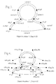
- the object outline is defined using bezier curves.
- Bezier curves are applied to the outline which result in the x, y coordinates shown.
- the depth map for the object may therefore be defined as ⁇ object number> ⁇ object depth> ⁇ x1, y1, x1 a, y1 a, x2b, y2b, x2, y2,....x1b, y1 b>
- Bezier curves may also be generated that require only 3 x, y coordinates as illustrated in figure 5 and may be defined as follows ⁇ object number > ⁇ object depth > ⁇ x1, y1, x1 a, y1 a, x2, y2, ... x8a, y8a >
- This method is preferable since it requires a smaller number of elements to define the curve.
- the object outline is defined using geometric shapes.
- Geometric shapes are applied to the outline which result in the construction shown.
- the circle forming the head will have a centre defined by x1, y1 and radius r1.
- Triangles can be described as x2a, y2a, x2b, y2b, x2c, y2c and similarly for other polygons.
- Each geometric shape may have the general form ⁇ shape > ⁇ parameters >
- the depth map for the object may therefore be defined as ⁇ object number> ⁇ object depth> ⁇ shape 1 > ⁇ parameters> whereas ⁇ shape n > ⁇ parameters>
- the outlines and/or depth maps created using any of these methods may be stored in any suitable analogue or digital format and medium, either with or without their associated 2D images.
- the storage may include, but not limited to, floppy disk, hard disk, CD-ROM, laser disk, DVD, RAM, ROM, magnetic recording tape, video tape, video cassette etc.
- the stored outlines and/or depth maps may be recalled at a later time and/or place to enable the reconstruction of the depth maps for the generation of distortion meshes for the generation of 3D images or for further adjustment and fine tuning.
- a distortion mesh may be used to convert a 2D image into 3D.
- This depth map itself being generated from additional information transmitted within the 2D video.
- the generation of a distortion grid from a depth map may take place in realtime, semi-realtime or offline and may be undertaken locally or, via any suitable transmission medium, at a remote location.
- the generation may be implemented in software or hardware.
- the information necessary to re-create the depth map may be transmitted.
- the depth map may then be reconstructed at the decoder and the conversion into a distortion grid undertaken.
- These conversions may be undertaken in either realtime, semi-realtime or offline at the receiving location and may be implemented in software or hardware.
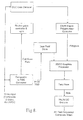
- the preferred method of conversion from depth map data into depth map then to distortion grid is as shown in a software flow chart in Figure 1 and in hardware in figure 2 .
- the individual elements of the software conversion process function as follows:
- Area & Depth Source - This is the information that is sent with the Image Sequence and in the preferred embodiment is contained in the VBI or MPEG data stream. It contains information as to the position, shape and depth of each object.
- the hard depth map is then blurred (gaussian, fast or other) to remove any hard edges.
- the blurring provides a smooth transition between the objects in order to eliminate image overlapping.
- the blurring is slightly weighted in the horizontal direction.
- the vertical blur helps stop image tearing by bleeding into the images above and below thus giving a smoother transition between near and far objects.
- the blurred depth map is then used as a source for displacement of the distortion grid, white being maximum displacement, black being no displacement.
- the amount of distortion along the horizontal axis is scaled according to the depth of the depth map at any given pixel location.
- the displacement for the left image is to the right, the right image displacement to the left.
- An overall forced parallax may be applied to the image so that the white (foreground) displaced objects are converged at screen level.
- the black (background) areas will then have a forced parallax equal to an unshifted image.
- the direction of displacement, and forced parallax may be varied to suite the particular requirements of the 3D display system on which the converted images are to be displayed.
- FIG. 2 A preferred embodiment of a hardware converter to generate separate left and right images from a distortion grid is shown in figure 2 , which could be fully digital.
- a method of implementing this process is shown in figure 2a and operates as follows.
- the system uses two line stores, which are multi-ported to allow simultaneous access.
- a line of video is written into one of the line stores while the other line store is being read to generate the output video signal.
- the line stores are swapped.
- the depth information is extracted from the video signal to regenerate the depth map for the current image.
- the depth map is translated into a pixel offset (of the distortion grid).
- the pixel offset is added to the pixel counter as the video line is read out of the line store.
- the pixel offset is a fractional value, so it is necessary to read the pixel values each side of the desired pixel and interpolate the intermediate value.
- the odd/even field signal from the video decoder is used to control the field sequential video output and to synchronise the viewer's shutter glasses to the output video signal.
- the basic circuitry may be duplicated to generate separate left and right video signals for 3D displays that require this video format.
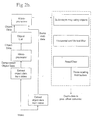
- a Functional block diagram of the DDC Decoder is shown in Figure 2b .
- the first process is to extract the object data from the incoming video which may be inserted in the VBI or MPEG data stream.
- the extracted data will be in compressed format and is subsequently decompressed using a microprocessor.
- the output from the microprocessor is the original object outline information and is again processed to produce the depth information for each object.
- This data is passed to a set of three rotating field buffers, the buffers being controlled by a microprocessor.
- the first buffer recreates the original depth maps.
- the depth maps are then passed to the next buffer where the horizontal and vertical blurs are applied. Once the blurring has been applied the resulting data is applied to the final buffer where the data is passed to the Depth to Pixel Offset Converter shown in Figure 2a . Once the data has been transferred to the Offset Converter the final buffer is cleared and is ready to receive the next depth map.
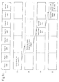
- the DDC Decoder process is illustrated in Figure 2c .
- This shows the process as a timing diagram and assumes that current microprocessors are not sufficiently fast to undertake all the decoding processes simultaneously.
- the decoding process is therefore undertaken sequentially in a pipe-line process. As microprocessor performance improves it is expected that a number, if not all, of these processes will be undertaken simultaneously.
- Figure 2c (1) four frames of video are shown, each frame comprising odd and even fields.
- the object list for frame four is generated whilst at (3) the depth map for frame 4 is generated.
- the horizontal and vertical blurs are applied and at (5) the depth map for frame 4 is output and the buffer is cleared ready for the next object list.
- Figure 2c illustrates the process for an individual frame and in practice, at any one time, depth maps for four different frames are being generated by different sections of the hardware.
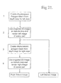
- the decoding process may be more easily understood by explaining the process as if performed manually. This is illustrated by the flow chart in Figure 9 and subsequent drawings.
- the process commences by producing an undistorted mesh, using as many polygons in the xy plane as necessary to achieve a relatively smooth deformation. In the preferred embodiment 10,000 polygons per field may typically be used.
- An example of a section of undistorted mesh is shown in Figure 10 .
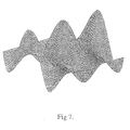
- the depth map for the object to be converted into 3D (in this example, a cone whose tip is orientated towards the viewer as per Figure 11 ) is applied to the mesh which is modified such that the z axis elevation of the mesh's polygons is dependant upon the value of the corresponding pixel in the depth map. This is illustrated in Figure 12 .
- the next step in the process is to translate the z axis elevation of each polygon into an equivalent x displacement.
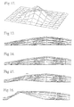
- This is illustrated in Figures 13 through 16 .
- an x axis section through the z elevation mesh is shown.
- Figure 15 shows the effect of the rotation at the 45° point and Figure 16 after 90° of rotation. This process is repeated for all x rows which effectively translates the depth maps z axis elevations into an x displacement.
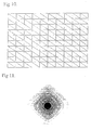
- the next step in the process is to map the original video frame onto an undistorted mesh as per Figure 17 .
- the undistorted mesh is then morphed into the x displacement map generated previously as per Figure 18 .
- the resulting video image will then distend according to the mesh's displacement, Figure 19 .
- This has the same effect as stretching the image as described in our previous application PCT/AU96/00820 .
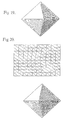
- the stretched image may be used to form one view of a stereo pair, the other being formed by rotating the points in Figure 13 by -90° which will produce a mesh and corresponding image as shown in Figure 20 .
- FIG 8 A block diagram of a hardware DDC decoder based upon a 2D/3D graphics processor is shown in Figure 8 .
- the extraction and generation of the depth maps from the DDC data remains as previously described and illustrated in Figure 2b .
- the operation of the decoder can be as follows. Incoming video is passed to the DDC data decoder which extracts the DDC information from the video stream and recovers the depth map for each video field.
- the video is also converted into RGB, YUV or other standard video format and placed into a dual field store. This enables a video field to be read out into the 2D/3D graphics processor at the same time as a new field is being loaded.
- the depth map output from the DDC data decoder is passed to the Depth Map to Polygon mesh converter which defines the shape of the polygons to be processed by the 2D/3D graphics processor.
- the other input to the graphics processor is the original 2D video image which is used as a texture map to which the polygons are applied.
- the output from the graphics processor is passed to a field store that enables the video to be read out in an interlaced format. This is subsequently passed to a PAL/NTSC encoder, the output of which will be a standard field sequential 3D video signal.
- the decoder retains in memory a sequence of previously transmitted depth maps for reuse rather than require to re-process a depth map that has been sent previously.
- Either the depth map or the resulting distortion mesh may be retained in the decoder's memory which may be volatile or nonvolatile and comprises, although not limited to, RAM, EEPROM, flash memory, magnetic or optical storage etc. It is also intended that generic depth maps and/or distortion grids be stored in the decoder. This will enable frequently occurring scenes to be converted without the need to transmit or convert the depth map.
- the correct depth map may be selected by including data in the video signal that uniquely identifies to the decoder which default depth map to apply. It is also intended that the decoder should have the capability of receiving new or altered depth maps so as to enable a library of depth maps and/or distortion grids to be maintained within the decoder.
- This library may be held within, although not limited to, the following media RAM, EEPROM, flash memory, magnetic or optical storage etc. It is intended that the library be updated by the transmission of specific depth maps or distortion grids that are included in the video signal. It is also intended that the library could be maintained by means of external or internal plug-in modules containing such depth maps or distortion grids and by down loading to the decoder via the video signal, modem or the Internet. Other means of maintaining the library will be obvious to those skilled in the art.
- the general format of DDC Data included in the video signal may, in the preferred embodiment, include a header flag which indicates to the decoder the nature of the following data.
- a header flag which indicates to the decoder the nature of the following data.
- a number of existing standards could be used for this format which in general will have the following format; ⁇ Flag# > ⁇ data to be acted upon by the decoder >
- flags include, although not limited to, the following;
- each data packet could be a different length which would uniquely define each packet and alleviate the need for a Flag.
- the decoder should be able to determine the most suitable depth map to apply to the associated 3D image by automatically making a selection from a nominated range within the library.
- the DDC data could direct the decoder to search the library of depth maps between specific index points or by generic category i.e. Evening News, Horse Race. The decoder would then select the appropriate map based upon object size, shape, speed, direction, colour, shading, obscuration etc.
- the original depth map, created during the encoding process can be made available in a suitable format for use with 3D display systems that require a 2D image and object depth information.
- These displays may be autostereoscopic and/or volumetric in nature.
- the mesh distortion process may be defined by a mathematical algorithm.
- these parameters may be stored in memory within the decoder in the form of a library and recalled by sending the library index within the DDC data.
- direction and delay can be made by considering an overall motion vector within the 2D image and selecting these parameters based upon the size, direction and stability of the vector. In the prior art it has been necessary to perform these calculations in real time at the viewing location requiring substantial processing capabilities. It has been found that a preferred method is to calculate the motion vectors, and hence the direction and amount of field delay, at the transmission location and then transmit these values as part of the video signal. Thus in a preferred embodiment the transmitted data would be as follows; ⁇ Flag9 > ⁇ direction and delay > where ⁇ direction and delay > would typically be in the range -4 to +4.
- the DDC decoder could then recover this data and use it to insert the correct amount and direction of field delay into the processed images.
- the distortion mesh may also be obtained in realtime by the addition of a camera to an existing 2D video or film camera, which, using a variable focus lens and a sharpness detecting algorithm, determines the depth of objects in the image being viewed by the camera.
- Object depth may be obtained from a stereo pair of cameras whereby correlation between pixels in each image indicates object depth.
- the output from these configurations, before processing to provide distortion mesh data, may be used to generate depth maps. This is achieved by processing the original 2D image and applying shading, or other indications, to indicate object depth as explained in this disclosure.
- the outline of each object may be obtained from object characteristics such as object size, colour, speed of motion, shading, texture, brightness, obscuration as well as differences between previous and current and future images.
- Neural networks and expert systems may also be used to assist with identifying objects. It is also proposed to shift the image within the camera so that a physical offset of subsequent images on the camera's image sensor are obtained. This shift may be produced optically, electro-optically, mechanically, electro-mechanically, electronically or other methods known to those skilled in the art. The shift may be in a single direction i.e. x or multiple directions either sequentially or randomly. The shift of objects on the camera's sensor will be greater for those objects that are closer to the camera. By correlating the pixels in successive images the depth of each object may be determined. Alternatively a plurality of cameras could be used.
- Other techniques may be used to determine the depth of objects within a scene. These include, but are not limited to, the use of range finders operating on optical, laser, ultrasonic or microwave principles or the projection of grids over objects within the scene and determining the depth of an object from the resulting distortion of the grids.
- a number of Computer Aided Drawing (CAD) software packages enable wire frame models of the images being drawn to be produced. These wire frame models, which are a projection of the facets of the object, can be used to determine the position of objects within a scene.
- CAD Computer Aided Drawing
- part of the rendering process of 3D non stereoscopic images from packages like 3D Studio allows the distance from the camera to each pixel to be output.
- This render can produce a gray scale image which has the closest object appearing white, and the furthest point from the camera appearing black.
- This gray scale map may be used as a compatible depth map for conversion into stereoscopic 3D.
Landscapes
- Engineering & Computer Science (AREA)
- Physics & Mathematics (AREA)
- General Physics & Mathematics (AREA)
- Theoretical Computer Science (AREA)
- Multimedia (AREA)
- Computer Vision & Pattern Recognition (AREA)
- Signal Processing (AREA)
- Processing Or Creating Images (AREA)
- Testing, Inspecting, Measuring Of Stereoscopic Televisions And Televisions (AREA)
- Compression Or Coding Systems Of Tv Signals (AREA)
- Image Processing (AREA)
- Image Analysis (AREA)
Applications Claiming Priority (3)
| Application Number | Priority Date | Filing Date | Title |
|---|---|---|---|
| AUPP0778A AUPP077897A0 (en) | 1997-12-05 | 1997-12-05 | Improved image conversion and encoding techniques |
| AUPP2865A AUPP286598A0 (en) | 1998-04-08 | 1998-04-08 | Improved image conversion and encoding techniques |
| EP98960865A EP1044432A4 (fr) | 1997-12-05 | 1998-12-03 | Conversion d'images amelioree et techniques de codage |
Related Parent Applications (2)
| Application Number | Title | Priority Date | Filing Date |
|---|---|---|---|
| EP98960865.8 Division | 1998-12-03 | ||
| EP98960865A Division EP1044432A4 (fr) | 1997-12-05 | 1998-12-03 | Conversion d'images amelioree et techniques de codage |
Publications (2)
| Publication Number | Publication Date |
|---|---|
| EP2252071A2 true EP2252071A2 (fr) | 2010-11-17 |
| EP2252071A3 EP2252071A3 (fr) | 2017-04-12 |
Family
ID=25645669
Family Applications (2)
| Application Number | Title | Priority Date | Filing Date |
|---|---|---|---|
| EP10173075.2A Withdrawn EP2252071A3 (fr) | 1997-12-05 | 1998-12-03 | Conversion d'images améliorée et techniques de codage |
| EP98960865A Withdrawn EP1044432A4 (fr) | 1997-12-05 | 1998-12-03 | Conversion d'images amelioree et techniques de codage |
Family Applications After (1)
| Application Number | Title | Priority Date | Filing Date |
|---|---|---|---|
| EP98960865A Withdrawn EP1044432A4 (fr) | 1997-12-05 | 1998-12-03 | Conversion d'images amelioree et techniques de codage |
Country Status (9)
| Country | Link |
|---|---|
| US (3) | US7894633B1 (fr) |
| EP (2) | EP2252071A3 (fr) |
| JP (1) | JP4698831B2 (fr) |
| KR (1) | KR100560507B1 (fr) |
| CN (1) | CN1173296C (fr) |
| CA (1) | CA2305735C (fr) |
| ID (1) | ID27878A (fr) |
| MY (1) | MY124160A (fr) |
| WO (1) | WO1999030280A1 (fr) |
Cited By (1)
| Publication number | Priority date | Publication date | Assignee | Title |
|---|---|---|---|---|
| US9342861B2 (en) | 2011-04-19 | 2016-05-17 | Deluxe 3D Llc | Alternate viewpoint rendering |
Families Citing this family (214)
| Publication number | Priority date | Publication date | Assignee | Title |
|---|---|---|---|---|
| US8253729B1 (en) * | 1983-05-09 | 2012-08-28 | Geshwind David M | Trimming depth buffer during 2D to 3D conversion |
| US7116324B2 (en) | 1998-05-27 | 2006-10-03 | In-Three, Inc. | Method for minimizing visual artifacts converting two-dimensional motion pictures into three-dimensional motion pictures |
| US7116323B2 (en) | 1998-05-27 | 2006-10-03 | In-Three, Inc. | Method of hidden surface reconstruction for creating accurate three-dimensional images converted from two-dimensional images |
| AUPQ119799A0 (en) * | 1999-06-25 | 1999-07-22 | Dynamic Digital Depth Research Pty Ltd | Ddc/3 image conversion and encoding techniques |
| AUPQ416699A0 (en) * | 1999-11-19 | 1999-12-16 | Dynamic Digital Depth Research Pty Ltd | Depth map compression technique |
| MXPA03001171A (es) | 2000-08-09 | 2003-06-30 | Dynamic Digital Depth Res Pty | Tecnicas de conversion y codificacion de imagenes. |
| US6664962B1 (en) * | 2000-08-23 | 2003-12-16 | Nintendo Co., Ltd. | Shadow mapping in a low cost graphics system |
| US8401336B2 (en) | 2001-05-04 | 2013-03-19 | Legend3D, Inc. | System and method for rapid image sequence depth enhancement with augmented computer-generated elements |
| US9286941B2 (en) | 2001-05-04 | 2016-03-15 | Legend3D, Inc. | Image sequence enhancement and motion picture project management system |
| US8897596B1 (en) | 2001-05-04 | 2014-11-25 | Legend3D, Inc. | System and method for rapid image sequence depth enhancement with translucent elements |
| JP4708619B2 (ja) * | 2001-07-31 | 2011-06-22 | キヤノン株式会社 | 立体画像形成システムおよび立体画像形成方法 |
| US8369607B2 (en) | 2002-03-27 | 2013-02-05 | Sanyo Electric Co., Ltd. | Method and apparatus for processing three-dimensional images |
| WO2003081921A1 (fr) * | 2002-03-27 | 2003-10-02 | Sanyo Electric Co., Ltd. | Procede de traitement d'images tridimensionnelles et dispositif |
| US20030198290A1 (en) * | 2002-04-19 | 2003-10-23 | Dynamic Digital Depth Pty.Ltd. | Image encoding system |
| US7489812B2 (en) * | 2002-06-07 | 2009-02-10 | Dynamic Digital Depth Research Pty Ltd. | Conversion and encoding techniques |
| EP1588327B1 (fr) * | 2003-01-17 | 2018-09-26 | Koninklijke Philips N.V. | Acquisition de carte de profondeur complète |
| US20070008404A1 (en) * | 2003-05-07 | 2007-01-11 | Seijiro Tomita | Method and system for displaying stereoscopic image |
| CN100414566C (zh) * | 2003-06-19 | 2008-08-27 | 邓兴峰 | 平面图像全景重建立体图像的方法 |
| US7606417B2 (en) | 2004-08-16 | 2009-10-20 | Fotonation Vision Limited | Foreground/background segmentation in digital images with differential exposure calculations |
| US7680342B2 (en) * | 2004-08-16 | 2010-03-16 | Fotonation Vision Limited | Indoor/outdoor classification in digital images |
| JP4644669B2 (ja) * | 2003-08-05 | 2011-03-02 | コーニンクレッカ フィリップス エレクトロニクス エヌ ヴィ | マルチビュー画像の生成 |
| US7650036B2 (en) * | 2003-10-16 | 2010-01-19 | Sharp Laboratories Of America, Inc. | System and method for three-dimensional video coding |
| JP2007529070A (ja) * | 2004-03-12 | 2007-10-18 | コーニンクレッカ フィリップス エレクトロニクス エヌ ヴィ | 奥行きマップの生成方法及び装置 |
| US20050207486A1 (en) * | 2004-03-18 | 2005-09-22 | Sony Corporation | Three dimensional acquisition and visualization system for personal electronic devices |
| KR100585966B1 (ko) * | 2004-05-21 | 2006-06-01 | 한국전자통신연구원 | 3차원 입체 영상 부가 데이터를 이용한 3차원 입체 디지털방송 송/수신 장치 및 그 방법 |
| US7643672B2 (en) | 2004-10-21 | 2010-01-05 | Kazunari Era | Image processing apparatus, image pickup device and program therefor |
| US20090073170A1 (en) * | 2004-10-26 | 2009-03-19 | Koninklijke Philips Electronics, N.V. | Disparity map |
| US8774560B2 (en) * | 2005-01-11 | 2014-07-08 | University Of Central Florida Research Foundation, Inc. | System for manipulation, modification and editing of images via remote device |
| KR101199498B1 (ko) | 2005-03-31 | 2012-11-09 | 삼성전자주식회사 | 카메라 파라미터를 이용한 다시점 영상의 부호화 장치 및생성 장치, 그 방법과, 이를 수행하기 위한 프로그램이기록된 기록 매체 |
| US20080278487A1 (en) * | 2005-04-07 | 2008-11-13 | Nxp B.V. | Method and Device for Three-Dimensional Rendering |
| US20060233461A1 (en) * | 2005-04-19 | 2006-10-19 | Honeywell International Inc. | Systems and methods for transforming 2d image domain data into a 3d dense range map |
| KR100913173B1 (ko) * | 2005-07-05 | 2009-08-19 | 삼성모바일디스플레이주식회사 | 3d 그래픽 처리장치 및 이를 이용한 입체영상 표시장치 |
| KR100932977B1 (ko) | 2005-07-05 | 2009-12-21 | 삼성모바일디스플레이주식회사 | 입체 영상 표시 장치 |
| US8384763B2 (en) * | 2005-07-26 | 2013-02-26 | Her Majesty the Queen in right of Canada as represented by the Minster of Industry, Through the Communications Research Centre Canada | Generating a depth map from a two-dimensional source image for stereoscopic and multiview imaging |
| US8279221B2 (en) * | 2005-08-05 | 2012-10-02 | Samsung Display Co., Ltd. | 3D graphics processor and autostereoscopic display device using the same |
| US8274553B2 (en) * | 2005-10-18 | 2012-09-25 | Texas Instruments Incorporated | System and method for displaying stereoscopic digital motion picture images |
| US7523405B2 (en) * | 2005-11-16 | 2009-04-21 | Microsoft Corporation | Displaying 2D graphic content using depth wells |
| US7889244B2 (en) * | 2005-12-27 | 2011-02-15 | Panasonic Corporation | Image processing apparatus |
| US7692696B2 (en) * | 2005-12-27 | 2010-04-06 | Fotonation Vision Limited | Digital image acquisition system with portrait mode |
| JP5041458B2 (ja) * | 2006-02-09 | 2012-10-03 | 本田技研工業株式会社 | 三次元物体を検出する装置 |
| US7469071B2 (en) * | 2006-02-14 | 2008-12-23 | Fotonation Vision Limited | Image blurring |
| IES20060559A2 (en) * | 2006-02-14 | 2006-11-01 | Fotonation Vision Ltd | Automatic detection and correction of non-red flash eye defects |
| US20070189750A1 (en) * | 2006-02-16 | 2007-08-16 | Sony Corporation | Method of and apparatus for simultaneously capturing and generating multiple blurred images |
| IES20060564A2 (en) * | 2006-05-03 | 2006-11-01 | Fotonation Vision Ltd | Improved foreground / background separation |
| KR100699050B1 (ko) | 2006-06-30 | 2007-03-28 | 삼성전자주식회사 | 문자정보를 음성정보로 출력하는 이동통신 단말기 및 그방법 |
| US8970680B2 (en) | 2006-08-01 | 2015-03-03 | Qualcomm Incorporated | Real-time capturing and generating stereo images and videos with a monoscopic low power mobile device |
| TWI421541B (zh) * | 2006-10-26 | 2014-01-01 | Seereal Technologies Sa | Full image display device and method (2) |
| WO2008049907A1 (fr) * | 2006-10-26 | 2008-05-02 | Seereal Technologies S.A. | Système de génération de contenu 3d |
| CN101563935B (zh) * | 2006-12-19 | 2011-12-28 | 皇家飞利浦电子股份有限公司 | 将二维视频转换为三维视频的方法和系统 |
| KR100894874B1 (ko) * | 2007-01-10 | 2009-04-24 | 주식회사 리얼이미지 | 그물 지도를 이용한 이차원 영상으로부터의 입체 영상 생성장치 및 그 방법 |
| US8077964B2 (en) * | 2007-03-19 | 2011-12-13 | Sony Corporation | Two dimensional/three dimensional digital information acquisition and display device |
| JP4938093B2 (ja) * | 2007-03-23 | 2012-05-23 | トムソン ライセンシング | 2d−to−3d変換のための2d画像の領域分類のシステム及び方法 |
| US8488868B2 (en) * | 2007-04-03 | 2013-07-16 | Her Majesty The Queen In Right Of Canada, As Represented By The Minister Of Industry, Through The Communications Research Centre Canada | Generation of a depth map from a monoscopic color image for rendering stereoscopic still and video images |
| US8213711B2 (en) * | 2007-04-03 | 2012-07-03 | Her Majesty The Queen In Right Of Canada As Represented By The Minister Of Industry, Through The Communications Research Centre Canada | Method and graphical user interface for modifying depth maps |
| US10605610B2 (en) * | 2007-04-09 | 2020-03-31 | Ian Cummings | Apparatus and methods for reducing data transmission in wireless client-server navigation systems |
| JP4921591B2 (ja) * | 2007-07-03 | 2012-04-25 | コーニンクレッカ フィリップス エレクトロニクス エヌ ヴィ | 奥行きマップの計算 |
| EP2225725A2 (fr) * | 2007-12-20 | 2010-09-08 | Koninklijke Philips Electronics N.V. | Segmentation de données d'image |
| CN101483765B (zh) * | 2008-01-11 | 2011-09-21 | 华为技术有限公司 | 一种图像处理方法、编解码方法及装置 |
| US9094675B2 (en) * | 2008-02-29 | 2015-07-28 | Disney Enterprises Inc. | Processing image data from multiple cameras for motion pictures |
| KR101488199B1 (ko) * | 2008-03-12 | 2015-01-30 | 삼성전자주식회사 | 영상 처리 방법, 영상 재생 방법, 그 장치 및 기록매체 |
| FR2929421B1 (fr) * | 2008-03-25 | 2012-04-27 | Thales Sa | Procede de reconstruction synthetique tridimensionnelle d'objets exposes a une onde electromagnetique et/ou elastique |
| US8670607B2 (en) * | 2008-04-03 | 2014-03-11 | Nlt Technologies, Ltd. | Image processing method, image processing device and recording medium |
| KR100950046B1 (ko) * | 2008-04-10 | 2010-03-29 | 포항공과대학교 산학협력단 | 무안경식 3차원 입체 tv를 위한 고속 다시점 3차원 입체영상 합성 장치 및 방법 |
| KR101539935B1 (ko) * | 2008-06-24 | 2015-07-28 | 삼성전자주식회사 | 3차원 비디오 영상 처리 방법 및 장치 |
| TW201005673A (en) * | 2008-07-18 | 2010-02-01 | Ind Tech Res Inst | Example-based two-dimensional to three-dimensional image conversion method, computer readable medium therefor, and system |
| US8184196B2 (en) * | 2008-08-05 | 2012-05-22 | Qualcomm Incorporated | System and method to generate depth data using edge detection |
| KR101497503B1 (ko) | 2008-09-25 | 2015-03-04 | 삼성전자주식회사 | 2차원 영상의 3차원 영상 변환을 위한 깊이 맵 생성 방법 및 장치 |
| WO2010050691A2 (fr) | 2008-10-27 | 2010-05-06 | Samsung Electronics Co,. Ltd. | Procédés et appareil permettant de traiter et d'afficher une image |
| US8345956B2 (en) * | 2008-11-03 | 2013-01-01 | Microsoft Corporation | Converting 2D video into stereo video |
| US8606076B2 (en) * | 2008-11-24 | 2013-12-10 | Koninklijke Philips N.V. | 3D video reproduction matching the output format to the 3D processing ability of a display |
| EP2197217A1 (fr) * | 2008-12-15 | 2010-06-16 | Koninklijke Philips Electronics N.V. | Format vidéo 3D basé sur l'image |
| KR101659576B1 (ko) | 2009-02-17 | 2016-09-30 | 삼성전자주식회사 | 영상 처리 방법 및 장치 |
| WO2010095838A2 (fr) * | 2009-02-17 | 2010-08-26 | 삼성전자 주식회사 | Procédé et appareil de traitement d'image graphique |
| US20100309287A1 (en) * | 2009-03-20 | 2010-12-09 | Rodriguez Tony F | 3D Data Representation, Conveyance, and Use |
| US8620147B2 (en) * | 2009-03-31 | 2013-12-31 | Samsung Electronics Co., Ltd. | Method and apparatus for transmitting compressed data using digital data interface, and method and apparatus for receiving compressed data using digital data interface |
| CN101562755B (zh) * | 2009-05-19 | 2010-09-01 | 无锡景象数字技术有限公司 | 一种由平面视频制作3d视频的方法 |
| US9124874B2 (en) | 2009-06-05 | 2015-09-01 | Qualcomm Incorporated | Encoding of three-dimensional conversion information with two-dimensional video sequence |
| JP2011101229A (ja) * | 2009-11-06 | 2011-05-19 | Sony Corp | 表示制御装置、表示制御方法、プログラム、出力装置、および送信装置 |
| US8368696B2 (en) * | 2009-06-19 | 2013-02-05 | Sharp Laboratories Of America, Inc. | Temporal parallax induced display |
| TW201119353A (en) | 2009-06-24 | 2011-06-01 | Dolby Lab Licensing Corp | Perceptual depth placement for 3D objects |
| CN102498720B (zh) | 2009-06-24 | 2015-09-02 | 杜比实验室特许公司 | 在3d或多视图视频数据中嵌入字幕和/或图形叠层的方法 |
| CN101938670A (zh) * | 2009-06-26 | 2011-01-05 | Lg电子株式会社 | 图像显示装置及其操作方法 |
| US8872976B2 (en) | 2009-07-15 | 2014-10-28 | Home Box Office, Inc. | Identification of 3D format and graphics rendering on 3D displays |
| US10021377B2 (en) * | 2009-07-27 | 2018-07-10 | Koninklijke Philips N.V. | Combining 3D video and auxiliary data that is provided when not reveived |
| CN101968895A (zh) * | 2009-07-27 | 2011-02-09 | 鸿富锦精密工业(深圳)有限公司 | 二维图像转换系统及方法 |
| US20110025830A1 (en) | 2009-07-31 | 2011-02-03 | 3Dmedia Corporation | Methods, systems, and computer-readable storage media for generating stereoscopic content via depth map creation |
| WO2011014419A1 (fr) | 2009-07-31 | 2011-02-03 | 3Dmedia Corporation | Procédés, systèmes et supports de mémorisation lisibles par ordinateur pour création d'images tridimensionnelles (3d) d'une scène |
| US9380292B2 (en) | 2009-07-31 | 2016-06-28 | 3Dmedia Corporation | Methods, systems, and computer-readable storage media for generating three-dimensional (3D) images of a scene |
| US9294751B2 (en) | 2009-09-09 | 2016-03-22 | Mattel, Inc. | Method and system for disparity adjustment during stereoscopic zoom |
| US8624959B1 (en) * | 2009-09-11 | 2014-01-07 | The Boeing Company | Stereo video movies |
| JP5415217B2 (ja) * | 2009-10-02 | 2014-02-12 | パナソニック株式会社 | 三次元映像処理装置 |
| WO2011071978A1 (fr) * | 2009-12-09 | 2011-06-16 | StereoD, LLC | Rendu d'image en trois dimensions |
| US8538135B2 (en) | 2009-12-09 | 2013-09-17 | Deluxe 3D Llc | Pulling keys from color segmented images |
| US8638329B2 (en) * | 2009-12-09 | 2014-01-28 | Deluxe 3D Llc | Auto-stereoscopic interpolation |
| KR101281961B1 (ko) * | 2009-12-21 | 2013-07-03 | 한국전자통신연구원 | 깊이 영상 편집 방법 및 장치 |
| US9042636B2 (en) * | 2009-12-31 | 2015-05-26 | Disney Enterprises, Inc. | Apparatus and method for indicating depth of one or more pixels of a stereoscopic 3-D image comprised from a plurality of 2-D layers |
| US8743178B2 (en) * | 2010-01-05 | 2014-06-03 | Dolby Laboratories Licensing Corporation | Multi-view video format control |
| US20100164952A1 (en) * | 2010-01-25 | 2010-07-01 | Michael Roderick | Stereoscopic image production method and system |
| US8619122B2 (en) * | 2010-02-02 | 2013-12-31 | Microsoft Corporation | Depth camera compatibility |
| US8520935B2 (en) | 2010-02-04 | 2013-08-27 | Sony Corporation | 2D to 3D image conversion based on image content |
| US8442297B2 (en) * | 2010-02-23 | 2013-05-14 | Arinc Incorporated | Methods of evaluating the quality of two-dimensional matrix dot-peened marks on objects and mark verification systems |
| US9426441B2 (en) | 2010-03-08 | 2016-08-23 | Dolby Laboratories Licensing Corporation | Methods for carrying and transmitting 3D z-norm attributes in digital TV closed captioning |
| US9697751B2 (en) | 2010-03-09 | 2017-07-04 | Microsoft Technology Licensing, Llc | Interactive representation of clusters of geographical entities |
| US20110222757A1 (en) | 2010-03-10 | 2011-09-15 | Gbo 3D Technology Pte. Ltd. | Systems and methods for 2D image and spatial data capture for 3D stereo imaging |
| US8760498B2 (en) | 2011-03-14 | 2014-06-24 | Sony Corporation | Disparity data transport in standard caption service |
| KR101385514B1 (ko) * | 2010-06-08 | 2014-04-16 | 주식회사 에스칩스 | 깊이 맵 정보를 이용한 입체 영상 변환 방법 및 장치 |
| TWI462567B (zh) * | 2010-06-18 | 2014-11-21 | Realtek Semiconductor Corp | 三維處理電路及處理方法 |
| CN102300106B (zh) * | 2010-06-28 | 2014-03-12 | 瑞昱半导体股份有限公司 | 三维处理电路及处理方法 |
| US8848038B2 (en) * | 2010-07-09 | 2014-09-30 | Lg Electronics Inc. | Method and device for converting 3D images |
| US9344701B2 (en) | 2010-07-23 | 2016-05-17 | 3Dmedia Corporation | Methods, systems, and computer-readable storage media for identifying a rough depth map in a scene and for determining a stereo-base distance for three-dimensional (3D) content creation |
| CN103026387B (zh) * | 2010-07-26 | 2019-08-13 | 香港城市大学 | 用于从单一的图像生成多视图像的方法 |
| JP5687702B2 (ja) * | 2010-08-31 | 2015-03-18 | 本田技研工業株式会社 | 車両周辺監視装置 |
| US8655093B2 (en) * | 2010-09-02 | 2014-02-18 | Edge 3 Technologies, Inc. | Method and apparatus for performing segmentation of an image |
| US8582866B2 (en) | 2011-02-10 | 2013-11-12 | Edge 3 Technologies, Inc. | Method and apparatus for disparity computation in stereo images |
| US8666144B2 (en) | 2010-09-02 | 2014-03-04 | Edge 3 Technologies, Inc. | Method and apparatus for determining disparity of texture |
| US8831273B2 (en) | 2010-09-10 | 2014-09-09 | Reald Inc. | Methods and systems for pre-processing two-dimensional image files to be converted to three-dimensional image files |
| JP5502205B2 (ja) * | 2010-09-10 | 2014-05-28 | 富士フイルム株式会社 | 立体撮像装置および立体撮像方法 |
| US9485497B2 (en) | 2010-09-10 | 2016-11-01 | Reald Inc. | Systems and methods for converting two-dimensional images into three-dimensional images |
| WO2012032825A1 (fr) | 2010-09-10 | 2012-03-15 | 富士フイルム株式会社 | Dispositif d'imagerie en trois dimensions et procédé d'imagerie en trois dimensions |
| CA2810159C (fr) * | 2010-09-19 | 2017-04-18 | Lg Electronics Inc. | Procede et appareil pour traiter un signal de telediffusion pour un service de diffusion 3d (en 3 dimensions) |
| US20120068996A1 (en) * | 2010-09-21 | 2012-03-22 | Sony Corporation | Safe mode transition in 3d content rendering |
| JP5281624B2 (ja) * | 2010-09-29 | 2013-09-04 | 日本電信電話株式会社 | 画像符号化方法,画像復号方法,画像符号化装置,画像復号装置およびそれらのプログラム |
| JP5281623B2 (ja) * | 2010-09-29 | 2013-09-04 | 日本電信電話株式会社 | 画像符号化方法,画像復号方法,画像符号化装置,画像復号装置およびそれらのプログラム |
| US9305398B2 (en) | 2010-10-08 | 2016-04-05 | City University Of Hong Kong | Methods for creating and displaying two and three dimensional images on a digital canvas |
| US8619124B2 (en) * | 2010-10-14 | 2013-12-31 | Industrial Technology Research Institute | Video data processing systems and methods |
| JP5250604B2 (ja) * | 2010-10-26 | 2013-07-31 | 富士フイルム株式会社 | 立体画像表示装置、立体画像表示方法およびプログラム |
| WO2012061549A2 (fr) | 2010-11-03 | 2012-05-10 | 3Dmedia Corporation | Procédés, systèmes et produits logiciels informatiques pour créer des séquences vidéo tridimensionnelles |
| JP5559012B2 (ja) | 2010-11-12 | 2014-07-23 | キヤノン株式会社 | 画像処理装置及びその制御方法 |
| US20120120190A1 (en) * | 2010-11-16 | 2012-05-17 | Hung-Chia Lee | Display device for use in a frame sequential 3d display system and related 3d display system |
| US20120120191A1 (en) * | 2010-11-17 | 2012-05-17 | Hung-Chia Lee | Image processor for use in a frame sequential 3d display system and related 3d display system |
| WO2012078636A1 (fr) | 2010-12-07 | 2012-06-14 | University Of Iowa Research Foundation | Séparation optimale et conviviale d'arrière-plan d'objet |
| US12367578B2 (en) | 2010-12-07 | 2025-07-22 | University Of Iowa Research Foundation | Diagnosis of a disease condition using an automated diagnostic model |
| US10200671B2 (en) | 2010-12-27 | 2019-02-05 | 3Dmedia Corporation | Primary and auxiliary image capture devices for image processing and related methods |
| US8274552B2 (en) | 2010-12-27 | 2012-09-25 | 3Dmedia Corporation | Primary and auxiliary image capture devices for image processing and related methods |
| US9386294B2 (en) | 2011-01-05 | 2016-07-05 | Google Technology Holdings LLC | Method and apparatus for 3DTV image adjustment |
| US8624891B2 (en) * | 2011-01-17 | 2014-01-07 | Disney Enterprises, Inc. | Iterative reprojection of images |
| EP2665406B1 (fr) | 2011-01-20 | 2021-03-10 | University of Iowa Research Foundation | Détermination automatisée de rapport artérioveineux dans des images de vaisseaux sanguins |
| US20140035909A1 (en) * | 2011-01-20 | 2014-02-06 | University Of Iowa Research Foundation | Systems and methods for generating a three-dimensional shape from stereo color images |
| WO2012101582A1 (fr) * | 2011-01-24 | 2012-08-02 | Invision Biometrics Ltd. | Procédé et système d'acquisition, de représentation, de compression, et de transmission de données tridimensionnelles |
| US8730232B2 (en) | 2011-02-01 | 2014-05-20 | Legend3D, Inc. | Director-style based 2D to 3D movie conversion system and method |
| US9407904B2 (en) | 2013-05-01 | 2016-08-02 | Legend3D, Inc. | Method for creating 3D virtual reality from 2D images |
| US9288476B2 (en) | 2011-02-17 | 2016-03-15 | Legend3D, Inc. | System and method for real-time depth modification of stereo images of a virtual reality environment |
| US9282321B2 (en) | 2011-02-17 | 2016-03-08 | Legend3D, Inc. | 3D model multi-reviewer system |
| US9241147B2 (en) | 2013-05-01 | 2016-01-19 | Legend3D, Inc. | External depth map transformation method for conversion of two-dimensional images to stereoscopic images |
| JP5357199B2 (ja) * | 2011-03-14 | 2013-12-04 | 日本電信電話株式会社 | 画像符号化方法,画像復号方法,画像符号化装置,画像復号装置,画像符号化プログラムおよび画像復号プログラム |
| EP2697975A1 (fr) | 2011-04-15 | 2014-02-19 | Dolby Laboratories Licensing Corporation | Systèmes et procédés permettant le rendu d'images 3d indépendamment de la taille d'affichage et de la distance de visualisation |
| KR20120127992A (ko) * | 2011-05-16 | 2012-11-26 | 삼성전자주식회사 | 컨텐츠변환장치, 컨텐츠변환방법 및 그 저장 매체 |
| KR20120133571A (ko) * | 2011-05-31 | 2012-12-11 | 삼성전자주식회사 | 3d 영상변환장치, 3d 영상변환장치에 의해 구현되는 방법 및 그 저장매체 |
| US9509972B2 (en) | 2011-06-24 | 2016-11-29 | Lg Electronics Inc. | Encoding/decoding method and apparatus using a skip mode |
| US20130004059A1 (en) * | 2011-07-01 | 2013-01-03 | Amir Said | Aligning stereoscopic images |
| US9351028B2 (en) * | 2011-07-14 | 2016-05-24 | Qualcomm Incorporated | Wireless 3D streaming server |
| US20130016098A1 (en) * | 2011-07-17 | 2013-01-17 | Raster Labs, Inc. | Method for creating a 3-dimensional model from a 2-dimensional source image |
| WO2013025151A1 (fr) * | 2011-08-12 | 2013-02-21 | Telefonaktiebolaget L M Ericsson (Publ) | Signalisation de paramètres de caméra et/ou de profondeur |
| US8928729B2 (en) * | 2011-09-09 | 2015-01-06 | Disney Enterprises, Inc. | Systems and methods for converting video |
| US8995755B2 (en) | 2011-09-30 | 2015-03-31 | Cyberlink Corp. | Two-dimensional to stereoscopic conversion systems and methods |
| AU2012318854B2 (en) | 2011-10-05 | 2016-01-28 | Bitanimate, Inc. | Resolution enhanced 3D video rendering systems and methods |
| CN103096026A (zh) * | 2011-10-31 | 2013-05-08 | 鸿富锦精密工业(深圳)有限公司 | 安全监控系统及安全监控方法 |
| KR101330523B1 (ko) | 2011-11-29 | 2013-11-18 | (주)리얼디스퀘어 | 2차원 영상을 3차원 영상으로 변환하는 영상 변환 장치와 방법 및 그에 대한 기록매체 |
| WO2013081304A1 (fr) * | 2011-11-28 | 2013-06-06 | 에스케이플래닛 주식회사 | Appareil et procédé de conversion d'image pour convertir une image bidimensionnelle en une image tridimensionnelle et support d'enregistrement correspondant |
| KR101390961B1 (ko) | 2011-11-29 | 2014-05-07 | (주)리얼디스퀘어 | 2차원 영상을 3차원 영상으로 변환하는 영상 변환 시스템과 방법 및 그에 대한 기록매체 |
| KR101388668B1 (ko) * | 2011-11-29 | 2014-04-25 | (주)리얼디스퀘어 | 2차원 영상을 3차원 영상으로 변환하는 영상 변환 장치와 방법 및 그에 대한 기록매체 |
| US20130141433A1 (en) * | 2011-12-02 | 2013-06-06 | Per Astrand | Methods, Systems and Computer Program Products for Creating Three Dimensional Meshes from Two Dimensional Images |
| US9530060B2 (en) * | 2012-01-17 | 2016-12-27 | Avigilon Fortress Corporation | System and method for building automation using video content analysis with depth sensing |
| TWI478102B (zh) * | 2012-01-20 | 2015-03-21 | Realtek Semiconductor Corp | 影像深度產生裝置與其方法 |
| US9324190B2 (en) | 2012-02-24 | 2016-04-26 | Matterport, Inc. | Capturing and aligning three-dimensional scenes |
| US10848731B2 (en) | 2012-02-24 | 2020-11-24 | Matterport, Inc. | Capturing and aligning panoramic image and depth data |
| US11282287B2 (en) | 2012-02-24 | 2022-03-22 | Matterport, Inc. | Employing three-dimensional (3D) data predicted from two-dimensional (2D) images using neural networks for 3D modeling applications and other applications |
| US9959634B2 (en) * | 2012-03-13 | 2018-05-01 | Google Llc | Method and system for identifying depth data associated with an object |
| US9552129B2 (en) | 2012-03-23 | 2017-01-24 | Microsoft Technology Licensing, Llc | Interactive visual representation of points of interest data |
| KR101356544B1 (ko) * | 2012-03-29 | 2014-02-19 | 한국과학기술원 | 3차원 입체영상 생성 방법 및 장치 |
| US9545196B2 (en) | 2012-05-04 | 2017-01-17 | University Of Iowa Research Foundation | Automated assessment of glaucoma loss from optical coherence tomography |
| US9838669B2 (en) * | 2012-08-23 | 2017-12-05 | Stmicroelectronics (Canada), Inc. | Apparatus and method for depth-based image scaling of 3D visual content |
| US20140062999A1 (en) * | 2012-09-05 | 2014-03-06 | Shenzhen China Star Optoelectronics Technology Co., Ltd. | Display system and display control method thereof |
| KR101648094B1 (ko) * | 2012-09-25 | 2016-08-12 | 니폰 덴신 덴와 가부시끼가이샤 | 화상 부호화 방법, 화상 복호 방법, 화상 부호화 장치, 화상 복호 장치, 화상 부호화 프로그램, 화상 복호 프로그램 및 기록매체 |
| US9250653B2 (en) | 2012-09-28 | 2016-02-02 | City University Of Hong Kong | Capturing, processing, and reconstructing audio and video content of mobile devices |
| US9007365B2 (en) | 2012-11-27 | 2015-04-14 | Legend3D, Inc. | Line depth augmentation system and method for conversion of 2D images to 3D images |
| US9547937B2 (en) | 2012-11-30 | 2017-01-17 | Legend3D, Inc. | Three-dimensional annotation system and method |
| US20140184596A1 (en) * | 2012-12-28 | 2014-07-03 | Microsoft Corporation | Image based rendering |
| US9214138B2 (en) | 2012-12-28 | 2015-12-15 | Microsoft Technology Licensing, Llc | Redundant pixel mitigation |
| US9135742B2 (en) | 2012-12-28 | 2015-09-15 | Microsoft Technology Licensing, Llc | View direction determination |
| US8983176B2 (en) * | 2013-01-02 | 2015-03-17 | International Business Machines Corporation | Image selection and masking using imported depth information |
| US9083960B2 (en) * | 2013-01-30 | 2015-07-14 | Qualcomm Incorporated | Real-time 3D reconstruction with power efficient depth sensor usage |
| US9007404B2 (en) | 2013-03-15 | 2015-04-14 | Legend3D, Inc. | Tilt-based look around effect image enhancement method |
| WO2014143891A1 (fr) | 2013-03-15 | 2014-09-18 | University Of Iowa Research Foundation | Séparation automatisée d'arbres binaires se chevauchant |
| US9438878B2 (en) | 2013-05-01 | 2016-09-06 | Legend3D, Inc. | Method of converting 2D video to 3D video using 3D object models |
| US9563955B1 (en) | 2013-05-15 | 2017-02-07 | Amazon Technologies, Inc. | Object tracking techniques |
| US9489774B2 (en) * | 2013-05-16 | 2016-11-08 | Empire Technology Development Llc | Three dimensional user interface in augmented reality |
| JP5862635B2 (ja) | 2013-10-11 | 2016-02-16 | カシオ計算機株式会社 | 画像処理装置、立体データ生成方法、及びプログラム |
| JP2015104016A (ja) * | 2013-11-26 | 2015-06-04 | キヤノン株式会社 | 被写体検出装置、撮像装置、被写体検出装置の制御方法、被写体検出装置の制御プログラムおよび記憶媒体 |
| CN103646426A (zh) * | 2013-12-13 | 2014-03-19 | 武汉恩倍思科技有限公司 | 一种将2d平面照片转换为3d立体照片的方法 |
| JP6118948B2 (ja) * | 2014-03-03 | 2017-04-19 | コンソーシアム・ピー・インコーポレーテッドConsortium P Incorporated | 除外区域を用いたリアルタイム位置検出 |
| US10410355B2 (en) | 2014-03-21 | 2019-09-10 | U.S. Department Of Veterans Affairs | Methods and systems for image analysis using non-euclidean deformed graphs |
| US9407896B2 (en) * | 2014-03-24 | 2016-08-02 | Hong Kong Applied Science and Technology Research Institute Company, Limited | Multi-view synthesis in real-time with fallback to 2D from 3D to reduce flicker in low or unstable stereo-matching image regions |
| US9449234B2 (en) | 2014-03-31 | 2016-09-20 | International Business Machines Corporation | Displaying relative motion of objects in an image |
| US9196027B2 (en) | 2014-03-31 | 2015-11-24 | International Business Machines Corporation | Automatic focus stacking of captured images |
| US9300857B2 (en) | 2014-04-09 | 2016-03-29 | International Business Machines Corporation | Real-time sharpening of raw digital images |
| US10122992B2 (en) | 2014-05-22 | 2018-11-06 | Disney Enterprises, Inc. | Parallax based monoscopic rendering |
| US9721385B2 (en) | 2015-02-10 | 2017-08-01 | Dreamworks Animation Llc | Generation of three-dimensional imagery from a two-dimensional image using a depth map |
| US9897806B2 (en) | 2015-02-10 | 2018-02-20 | Dreamworks Animation L.L.C. | Generation of three-dimensional imagery to supplement existing content |
| US10368104B1 (en) * | 2015-04-01 | 2019-07-30 | Rockwell Collins, Inc. | Systems and methods for transmission of synchronized physical and visible images for three dimensional display |
| US10115194B2 (en) | 2015-04-06 | 2018-10-30 | IDx, LLC | Systems and methods for feature detection in retinal images |
| DE102015210453B3 (de) | 2015-06-08 | 2016-10-13 | Bitmanagement Software GmbH | Verfahren und vorrichtung zum erzeugen von daten für eine zwei- oder dreidimensionale darstellung zumindest eines teils eines objekts und zum erzeugen der zwei- oder dreidimensionalen darstellung zumindest des teils des objekts |
| US9609307B1 (en) | 2015-09-17 | 2017-03-28 | Legend3D, Inc. | Method of converting 2D video to 3D video using machine learning |
| US10237531B2 (en) | 2016-06-22 | 2019-03-19 | Microsoft Technology Licensing, Llc | Discontinuity-aware reprojection |
| US10129523B2 (en) | 2016-06-22 | 2018-11-13 | Microsoft Technology Licensing, Llc | Depth-aware reprojection |
| US10558855B2 (en) * | 2016-08-17 | 2020-02-11 | Technologies Holdings Corp. | Vision system with teat detection |
| HK1224513A2 (zh) * | 2016-10-14 | 2017-08-18 | 智能3D有限公司 | 通过机器学习技术改进2d至3d的自动转换质量的方法 |
| WO2018172881A1 (fr) * | 2017-03-24 | 2018-09-27 | 株式会社半導体エネルギー研究所 | Dispositif à semi-conducteur, système d'affichage et dispositif électronique |
| US10229537B2 (en) * | 2017-08-02 | 2019-03-12 | Omnivor, Inc. | System and method for compressing and decompressing time-varying surface data of a 3-dimensional object using a video codec |
| US10692247B2 (en) * | 2017-08-02 | 2020-06-23 | Omnivor, Inc. | System and method for compressing and decompressing surface data of a 3-dimensional object using an image codec |
| US10740431B2 (en) | 2017-11-13 | 2020-08-11 | Samsung Electronics Co., Ltd | Apparatus and method of five dimensional (5D) video stabilization with camera and gyroscope fusion |
| EP3857451A4 (fr) * | 2018-09-25 | 2022-06-22 | Matterport, Inc. | Utilisation de données tridimensionnelles prédites à partir d'images bidimensionnelles à l'aide de réseaux neuronaux destinés à des applications de modélisation 3d |
| US10769848B1 (en) * | 2019-05-24 | 2020-09-08 | Adobe, Inc. | 3D object reconstruction using photometric mesh representation |
| US11501470B2 (en) | 2020-05-27 | 2022-11-15 | Microsoft Technology Licensing, Llc | Geometric encoding of data |
Family Cites Families (46)
| Publication number | Priority date | Publication date | Assignee | Title |
|---|---|---|---|---|
| US3772465A (en) * | 1971-06-09 | 1973-11-13 | Ass Of Motion Picture Televisi | Image modification of motion pictures |
| SE365325B (fr) * | 1971-11-04 | 1974-03-18 | Rothfjell R | |
| GB2037545B (en) * | 1978-05-31 | 1983-03-30 | Purdy H | Reproduction of character images particularly for typesetting apparatus |
| US4773098A (en) * | 1980-05-27 | 1988-09-20 | Texas Instruments Incorporated | Method of optical character recognition |
| US4783829A (en) * | 1983-02-23 | 1988-11-08 | Hitachi, Ltd. | Pattern recognition apparatus |
| US4925294A (en) * | 1986-12-17 | 1990-05-15 | Geshwind David M | Method to convert two dimensional motion pictures for three-dimensional systems |
| US5644654A (en) * | 1987-04-06 | 1997-07-01 | Canon Kabushiki Kaisha | Image processing apparatus capable of efficient coding of complex shape information |
| JPH0766445B2 (ja) * | 1988-09-09 | 1995-07-19 | 工業技術院長 | 画像処理方法 |
| US5109425A (en) * | 1988-09-30 | 1992-04-28 | The United States Of America As Represented By The United States National Aeronautics And Space Administration | Method and apparatus for predicting the direction of movement in machine vision |
| JPH03218581A (ja) * | 1989-11-01 | 1991-09-26 | Hitachi Ltd | 画像セグメンテーション方法 |
| US5130815A (en) | 1990-07-20 | 1992-07-14 | Mti Associates | Method and apparatus for encoding a video signal having multi-language capabilities |
| JPH0568268A (ja) * | 1991-03-04 | 1993-03-19 | Sharp Corp | 立体視画像作成装置および立体視画像作成方法 |
| US5537638A (en) * | 1991-10-25 | 1996-07-16 | Hitachi, Ltd. | Method and system for image mapping |
| FR2683648B1 (fr) | 1991-11-12 | 1996-12-13 | Apple Computer | Procede de choix d'objets dans une sequence d'images mobiles et piste d'essai de reussite correspondante. |
| US5333209A (en) * | 1992-03-24 | 1994-07-26 | At&T Bell Laboratories | Method of recognizing handwritten symbols |
| US5469535A (en) * | 1992-05-04 | 1995-11-21 | Midway Manufacturing Company | Three-dimensional, texture mapping display system |
| JPH0644755A (ja) * | 1992-07-24 | 1994-02-18 | Sony Corp | ビデオ信号の伝送方法及び記録装置 |
| KR0184313B1 (ko) | 1993-04-09 | 1999-05-01 | 모리시타 요이찌 | 디지털영상신호를 스크램블 및 디스크램블해서 전송하는 스크램블전송장치 |
| JPH0778267A (ja) * | 1993-07-09 | 1995-03-20 | Silicon Graphics Inc | 陰影を表示する方法及びコンピュータ制御表示システム |
| CA2106222C (fr) | 1993-09-15 | 2000-10-31 | Russell D. N. Mackinnon | Reseau de communication oriente objets |
| GB9322260D0 (en) | 1993-10-28 | 1993-12-15 | Pandora Int Ltd | Digital video processor |
| US5511153A (en) * | 1994-01-18 | 1996-04-23 | Massachusetts Institute Of Technology | Method and apparatus for three-dimensional, textured models from plural video images |
| US5640468A (en) * | 1994-04-28 | 1997-06-17 | Hsu; Shin-Yi | Method for identifying objects and features in an image |
| US5673377A (en) * | 1994-09-02 | 1997-09-30 | Ray Dream, Inc. | Method and system for displaying a representation of a three-dimensional object with surface features that conform to the surface of the three-dimensional object |
| JPH0877356A (ja) * | 1994-09-09 | 1996-03-22 | Fujitsu Ltd | 三次元多眼画像の処理方法及び処理装置 |
| JPH08138053A (ja) * | 1994-11-08 | 1996-05-31 | Canon Inc | 被写体情報処理装置及び遠隔装置 |
| US5790086A (en) * | 1995-01-04 | 1998-08-04 | Visualabs Inc. | 3-D imaging system |
| KR100414629B1 (ko) * | 1995-03-29 | 2004-05-03 | 산요덴키가부시키가이샤 | 3차원표시화상생성방법,깊이정보를이용한화상처리방법,깊이정보생성방법 |
| US5798762A (en) * | 1995-05-10 | 1998-08-25 | Cagent Technologies, Inc. | Controlling a real-time rendering engine using a list-based control mechanism |
| US5617334A (en) * | 1995-07-21 | 1997-04-01 | The Trustees Of Columbia University In The City Of New York | Multi-viewpoint digital video coder/decoder and method |
| US5864342A (en) * | 1995-08-04 | 1999-01-26 | Microsoft Corporation | Method and system for rendering graphical objects to image chunks |
| AUPN732395A0 (en) * | 1995-12-22 | 1996-01-25 | Xenotech Research Pty Ltd | Image conversion and encoding techniques |
| US5793900A (en) * | 1995-12-29 | 1998-08-11 | Stanford University | Generating categorical depth maps using passive defocus sensing |
| US5806005A (en) * | 1996-05-10 | 1998-09-08 | Ricoh Company, Ltd. | Wireless image transfer from a digital still video camera to a networked computer |
| GB9613039D0 (en) * | 1996-06-21 | 1996-08-28 | Philips Electronics Nv | Image data compression for interactive applications |
| JP3679512B2 (ja) * | 1996-07-05 | 2005-08-03 | キヤノン株式会社 | 画像抽出装置および方法 |
| US5809139A (en) * | 1996-09-13 | 1998-09-15 | Vivo Software, Inc. | Watermarking method and apparatus for compressed digital video |
| US6055330A (en) * | 1996-10-09 | 2000-04-25 | The Trustees Of Columbia University In The City Of New York | Methods and apparatus for performing digital image and video segmentation and compression using 3-D depth information |
| JPH10191020A (ja) * | 1996-12-20 | 1998-07-21 | Canon Inc | 被写体画像切出し方法及び装置 |
| US5974175A (en) | 1997-01-22 | 1999-10-26 | Fujitsu Limited | Image processing apparatus and method for detecting a contour of an object from images of a motion picture and extracting the object therefrom |
| JP3008875B2 (ja) * | 1997-02-25 | 2000-02-14 | 日本電気株式会社 | 被写体抽出装置 |
| US6031564A (en) * | 1997-07-07 | 2000-02-29 | Reveo, Inc. | Method and apparatus for monoscopic to stereoscopic image conversion |
| US6630931B1 (en) * | 1997-09-22 | 2003-10-07 | Intel Corporation | Generation of stereoscopic displays using image approximation |
| US6029173A (en) * | 1997-11-26 | 2000-02-22 | Navigation Technologies Corporation | Method and system for representation and use of shape information in geographic databases |
| US6504569B1 (en) * | 1998-04-22 | 2003-01-07 | Grass Valley (U.S.), Inc. | 2-D extended image generation from 3-D data extracted from a video sequence |
| AUPQ416699A0 (en) * | 1999-11-19 | 1999-12-16 | Dynamic Digital Depth Research Pty Ltd | Depth map compression technique |
-
1998
- 1998-12-03 MY MYPI98005481A patent/MY124160A/en unknown
- 1998-12-03 CN CNB988118491A patent/CN1173296C/zh not_active Expired - Fee Related
- 1998-12-03 WO PCT/AU1998/001005 patent/WO1999030280A1/fr not_active Ceased
- 1998-12-03 ID IDW20001305A patent/ID27878A/id unknown
- 1998-12-03 JP JP2000524763A patent/JP4698831B2/ja not_active Expired - Fee Related
- 1998-12-03 EP EP10173075.2A patent/EP2252071A3/fr not_active Withdrawn
- 1998-12-03 KR KR1020007005574A patent/KR100560507B1/ko not_active Expired - Fee Related
- 1998-12-03 CA CA002305735A patent/CA2305735C/fr not_active Expired - Fee Related
- 1998-12-03 EP EP98960865A patent/EP1044432A4/fr not_active Withdrawn
-
2000
- 2000-06-05 US US09/586,869 patent/US7894633B1/en not_active Expired - Fee Related
-
2003
- 2003-08-18 US US10/642,300 patent/US7551770B2/en not_active Expired - Fee Related
- 2003-08-18 US US10/642,490 patent/US7054478B2/en not_active Expired - Fee Related
Cited By (1)
| Publication number | Priority date | Publication date | Assignee | Title |
|---|---|---|---|---|
| US9342861B2 (en) | 2011-04-19 | 2016-05-17 | Deluxe 3D Llc | Alternate viewpoint rendering |
Also Published As
| Publication number | Publication date |
|---|---|
| US7054478B2 (en) | 2006-05-30 |
| EP1044432A1 (fr) | 2000-10-18 |
| JP4698831B2 (ja) | 2011-06-08 |
| WO1999030280A1 (fr) | 1999-06-17 |
| US20040032980A1 (en) | 2004-02-19 |
| EP1044432A4 (fr) | 2007-02-21 |
| MY124160A (en) | 2006-06-30 |
| ID27878A (id) | 2001-05-03 |
| US7551770B2 (en) | 2009-06-23 |
| CN1281569A (zh) | 2001-01-24 |
| JP2001526477A (ja) | 2001-12-18 |
| EP2252071A3 (fr) | 2017-04-12 |
| US7894633B1 (en) | 2011-02-22 |
| KR20010032346A (ko) | 2001-04-16 |
| KR100560507B1 (ko) | 2006-03-15 |
| US20040032488A1 (en) | 2004-02-19 |
| CA2305735C (fr) | 2008-01-08 |
| CN1173296C (zh) | 2004-10-27 |
| CA2305735A1 (fr) | 1999-06-17 |
Similar Documents
| Publication | Publication Date | Title |
|---|---|---|
| CA2305735C (fr) | Conversion d'images amelioree et techniques de codage | |
| US6496598B1 (en) | Image processing method and apparatus | |
| AU760594B2 (en) | System and method for creating 3D models from 2D sequential image data | |
| KR101038452B1 (ko) | 멀티뷰 이미지 생성 | |
| US8488868B2 (en) | Generation of a depth map from a monoscopic color image for rendering stereoscopic still and video images | |
| US9986258B2 (en) | Efficient encoding of multiple views | |
| JP5243612B2 (ja) | 中間画像合成およびマルチビューデータ信号抽出 | |
| US20090219383A1 (en) | Image depth augmentation system and method | |
| US20150379720A1 (en) | Methods for converting two-dimensional images into three-dimensional images | |
| JP2022533754A (ja) | ボリュメトリック映像の符号化および復号化のための方法、装置、およびコンピュータプログラム製品 | |
| EP3298578B1 (fr) | Procédé et appareil pour déterminer une carte de profondeur pour une image | |
| AU738692B2 (en) | Improved image conversion and encoding techniques | |
| HK1146170A (en) | Improved image conversion and encoding techniques | |
| CN115314658A (zh) | 基于三维显示的视频通信方法及系统 | |
| MXPA00005355A (en) | Improved image conversion and encoding techniques | |
| CN116866540A (zh) | 图像渲染方法、系统、装置及存储介质 |
Legal Events
| Date | Code | Title | Description |
|---|---|---|---|
| PUAI | Public reference made under article 153(3) epc to a published international application that has entered the european phase |
Free format text: ORIGINAL CODE: 0009012 |
|
| 17P | Request for examination filed |
Effective date: 20100915 |
|
| AC | Divisional application: reference to earlier application |
Ref document number: 1044432 Country of ref document: EP Kind code of ref document: P |
|
| AK | Designated contracting states |
Kind code of ref document: A2 Designated state(s): AT BE CH CY DE DK ES FI FR GB GR IE IT LI LU MC NL PT SE |
|
| REG | Reference to a national code |
Ref country code: HK Ref legal event code: DE Ref document number: 1146170 Country of ref document: HK |
|
| RIC1 | Information provided on ipc code assigned before grant |
Ipc: G06T 9/00 20060101ALI20161206BHEP Ipc: G06T 7/00 20170101ALI20161206BHEP Ipc: G06K 9/48 20060101ALI20161206BHEP Ipc: H04N 13/00 20060101AFI20161206BHEP Ipc: H04N 13/02 20060101ALI20161206BHEP |
|
| PUAL | Search report despatched |
Free format text: ORIGINAL CODE: 0009013 |
|
| AK | Designated contracting states |
Kind code of ref document: A3 Designated state(s): AT BE CH CY DE DK ES FI FR GB GR IE IT LI LU MC NL PT SE |
|
| RIC1 | Information provided on ipc code assigned before grant |
Ipc: G06T 7/00 20170101ALI20170309BHEP Ipc: H04N 13/00 20060101AFI20170309BHEP Ipc: H04N 13/02 20060101ALI20170309BHEP Ipc: G06K 9/48 20060101ALI20170309BHEP Ipc: G06T 9/00 20060101ALI20170309BHEP |
|
| STAA | Information on the status of an ep patent application or granted ep patent |
Free format text: STATUS: THE APPLICATION IS DEEMED TO BE WITHDRAWN |
|
| 18D | Application deemed to be withdrawn |
Effective date: 20171013 |
|
| REG | Reference to a national code |
Ref country code: HK Ref legal event code: WD Ref document number: 1146170 Country of ref document: HK |