EP2256342B1 - Procédé de freinage d'urgence d'une éolienne et éolienne dotée d'un réglage de pale de rotor pour le freinage d'urgence - Google Patents
Procédé de freinage d'urgence d'une éolienne et éolienne dotée d'un réglage de pale de rotor pour le freinage d'urgence Download PDFInfo
- Publication number
- EP2256342B1 EP2256342B1 EP09007124.2A EP09007124A EP2256342B1 EP 2256342 B1 EP2256342 B1 EP 2256342B1 EP 09007124 A EP09007124 A EP 09007124A EP 2256342 B1 EP2256342 B1 EP 2256342B1
- Authority
- EP
- European Patent Office
- Prior art keywords
- speed
- rotor blade
- blade
- predetermined
- pitch angle
- Prior art date
- Legal status (The legal status is an assumption and is not a legal conclusion. Google has not performed a legal analysis and makes no representation as to the accuracy of the status listed.)
- Active
Links
Images



Classifications
-
- F—MECHANICAL ENGINEERING; LIGHTING; HEATING; WEAPONS; BLASTING
- F03—MACHINES OR ENGINES FOR LIQUIDS; WIND, SPRING, OR WEIGHT MOTORS; PRODUCING MECHANICAL POWER OR A REACTIVE PROPULSIVE THRUST, NOT OTHERWISE PROVIDED FOR
- F03D—WIND MOTORS
- F03D7/00—Controlling wind motors
- F03D7/02—Controlling wind motors the wind motors having rotation axis substantially parallel to the air flow entering the rotor
- F03D7/0264—Controlling wind motors the wind motors having rotation axis substantially parallel to the air flow entering the rotor for stopping; controlling in emergency situations
-
- F—MECHANICAL ENGINEERING; LIGHTING; HEATING; WEAPONS; BLASTING
- F03—MACHINES OR ENGINES FOR LIQUIDS; WIND, SPRING, OR WEIGHT MOTORS; PRODUCING MECHANICAL POWER OR A REACTIVE PROPULSIVE THRUST, NOT OTHERWISE PROVIDED FOR
- F03D—WIND MOTORS
- F03D7/00—Controlling wind motors
- F03D7/02—Controlling wind motors the wind motors having rotation axis substantially parallel to the air flow entering the rotor
- F03D7/022—Adjusting aerodynamic properties of the blades
- F03D7/0224—Adjusting blade pitch
-
- F—MECHANICAL ENGINEERING; LIGHTING; HEATING; WEAPONS; BLASTING
- F03—MACHINES OR ENGINES FOR LIQUIDS; WIND, SPRING, OR WEIGHT MOTORS; PRODUCING MECHANICAL POWER OR A REACTIVE PROPULSIVE THRUST, NOT OTHERWISE PROVIDED FOR
- F03D—WIND MOTORS
- F03D7/00—Controlling wind motors
- F03D7/02—Controlling wind motors the wind motors having rotation axis substantially parallel to the air flow entering the rotor
- F03D7/022—Adjusting aerodynamic properties of the blades
- F03D7/024—Adjusting aerodynamic properties of the blades of individual blades
-
- F—MECHANICAL ENGINEERING; LIGHTING; HEATING; WEAPONS; BLASTING
- F03—MACHINES OR ENGINES FOR LIQUIDS; WIND, SPRING, OR WEIGHT MOTORS; PRODUCING MECHANICAL POWER OR A REACTIVE PROPULSIVE THRUST, NOT OTHERWISE PROVIDED FOR
- F03D—WIND MOTORS
- F03D7/00—Controlling wind motors
- F03D7/02—Controlling wind motors the wind motors having rotation axis substantially parallel to the air flow entering the rotor
- F03D7/0244—Controlling wind motors the wind motors having rotation axis substantially parallel to the air flow entering the rotor for braking
-
- F—MECHANICAL ENGINEERING; LIGHTING; HEATING; WEAPONS; BLASTING
- F03—MACHINES OR ENGINES FOR LIQUIDS; WIND, SPRING, OR WEIGHT MOTORS; PRODUCING MECHANICAL POWER OR A REACTIVE PROPULSIVE THRUST, NOT OTHERWISE PROVIDED FOR
- F03D—WIND MOTORS
- F03D7/00—Controlling wind motors
- F03D7/02—Controlling wind motors the wind motors having rotation axis substantially parallel to the air flow entering the rotor
- F03D7/04—Automatic control; Regulation
- F03D7/042—Automatic control; Regulation by means of an electrical or electronic controller
-
- F—MECHANICAL ENGINEERING; LIGHTING; HEATING; WEAPONS; BLASTING
- F05—INDEXING SCHEMES RELATING TO ENGINES OR PUMPS IN VARIOUS SUBCLASSES OF CLASSES F01-F04
- F05B—INDEXING SCHEME RELATING TO WIND, SPRING, WEIGHT, INERTIA OR LIKE MOTORS, TO MACHINES OR ENGINES FOR LIQUIDS COVERED BY SUBCLASSES F03B, F03D AND F03G
- F05B2260/00—Function
- F05B2260/70—Adjusting of angle of incidence or attack of rotating blades
- F05B2260/74—Adjusting of angle of incidence or attack of rotating blades by turning around an axis perpendicular the rotor centre line
-
- F—MECHANICAL ENGINEERING; LIGHTING; HEATING; WEAPONS; BLASTING
- F05—INDEXING SCHEMES RELATING TO ENGINES OR PUMPS IN VARIOUS SUBCLASSES OF CLASSES F01-F04
- F05B—INDEXING SCHEME RELATING TO WIND, SPRING, WEIGHT, INERTIA OR LIKE MOTORS, TO MACHINES OR ENGINES FOR LIQUIDS COVERED BY SUBCLASSES F03B, F03D AND F03G
- F05B2260/00—Function
- F05B2260/96—Preventing, counteracting or reducing vibration or noise
-
- F—MECHANICAL ENGINEERING; LIGHTING; HEATING; WEAPONS; BLASTING
- F05—INDEXING SCHEMES RELATING TO ENGINES OR PUMPS IN VARIOUS SUBCLASSES OF CLASSES F01-F04
- F05B—INDEXING SCHEME RELATING TO WIND, SPRING, WEIGHT, INERTIA OR LIKE MOTORS, TO MACHINES OR ENGINES FOR LIQUIDS COVERED BY SUBCLASSES F03B, F03D AND F03G
- F05B2270/00—Control
- F05B2270/10—Purpose of the control system
- F05B2270/107—Purpose of the control system to cope with emergencies
-
- Y—GENERAL TAGGING OF NEW TECHNOLOGICAL DEVELOPMENTS; GENERAL TAGGING OF CROSS-SECTIONAL TECHNOLOGIES SPANNING OVER SEVERAL SECTIONS OF THE IPC; TECHNICAL SUBJECTS COVERED BY FORMER USPC CROSS-REFERENCE ART COLLECTIONS [XRACs] AND DIGESTS
- Y02—TECHNOLOGIES OR APPLICATIONS FOR MITIGATION OR ADAPTATION AGAINST CLIMATE CHANGE
- Y02E—REDUCTION OF GREENHOUSE GAS [GHG] EMISSIONS, RELATED TO ENERGY GENERATION, TRANSMISSION OR DISTRIBUTION
- Y02E10/00—Energy generation through renewable energy sources
- Y02E10/70—Wind energy
- Y02E10/72—Wind turbines with rotation axis in wind direction
Definitions
- the present invention relates to a method for emergency braking of a wind turbine, in which at least one rotor blade of the wind turbine is adjusted to its flag position.
- the invention further relates to a wind energy plant with at least one rotor blade and at least one rotor blade adjustment device which sets the blade pitch for the at least one rotor blade and can adjust the at least one rotor blade into its feathering position in response to a control signal for emergency braking.
- the blade pitch of the rotor blade is defined as the angle that the chord of the rotor blade encloses with the plane of rotation.
- the feathering position of the rotor blade is that position of the rotor blade in which the chord of the rotor blade is approximately perpendicular to the plane of rotation of the rotor blade. In the flag position, either the leading edge or the trailing edge of the rotor blade is turned into the wind so that no buoyancy can arise on the blade profile.
- Out DE 10 2005 034 899 A1 is a wind turbine with single pitch known.
- a selector When moving the rotor blade into its feathering position, a selector is provided which, at the beginning of the traversing operation, selects a regulator regime which provides a high adjustment speed for the rotor blade.
- a lower adjustment speed is selected for the rotor blade.
- WO 2009/010059 A2 a method for adjusting the rotor blades during the stopping of the rotor is known.
- the rotor blades are moved to a position in which no thrust force is absorbed by the rotor. Subsequently, with the present aerodynamic thrust of the rotor is controlled so that the thrust is substantially zero or counteracts the direction of movement of the tower with its first natural frequency.
- the invention is based on the object in the emergency braking of the wind turbine to reduce the loads occurring on the rotor blades and the rotor blade connections and the tower head oscillations.
- the object of the invention is achieved by a method having the features of claim 1. Likewise, the object of the invention is achieved by a wind turbine with the features of claim 7. Advantageous embodiments form the subject of the dependent claims.
- the inventive method is used for emergency braking a wind turbine, in which at least one rotor blade of the wind turbine is moved to its flag position.
- the adjustment of the blade pitch also referred to as the pitch angle, acts as an aerodynamic brake in the feathering position and is independent of other components to drive the wind turbine to the shutdown position.
- the adjustment process with which the rotor blade is brought into its feathered position is distinguished into a first phase and a second phase. In the first phase, which begins immediately after the movement into the feathered position has begun, the at least one rotor blade is adjusted at a first speed.
- the at least one rotor blade is adjusted from a predetermined first blade pitch angle at a second speed.
- the second speed is increased until reaching a maximum speed and / or until reaching a second predetermined blade pitch angle.
- the second speed is increased continuously or stepwise in the second phase.
- the invention is based on the finding that in the second phase of the emergency drive, since the rotational speed of the rotor and drive train already reduced and the rotor blade only a small amount of lift is present, an increase in the pitch without increasing the loads on the rotor blades or the tower head vibrations is possible.
- the method consists in that in the first phase, in which the rotor blade still absorbs a moment from the wind and thus acts on strong forces acting on it, an adjustment of the rotor blade can take place at a lower speed than is hitherto known from the prior art ,
- the forces acting on the wind energy plant and in particular on the rotor blades and on the tower head can be reduced without increasing the time to reach the flag position.
- the impact torque at the blade connection and the deflection of the tower head increase. These are damped vibrations that stop after the braking process has ended.
- the amplitudes of these oscillations can be significantly reduced, in particular the low adjustment speed in the first phase has the effect of damping vibrations for the tower head oscillation.
- EP 1 701 034 A2 is initially adjusted at a lower speed in the inventive method and the transition to the second phase is independent of the deflection of the tower head.
- the first speed with which the rotor blade is adjusted in the first phase is constant over the duration of the first phase.
- the first predetermined blade pitch is in a range from which low loads on the rotor blade, preferably between 30 ° and 50 °.
- a third phase is provided, which is passed through after the first phase and before the second phase of the adjustment process.
- a third predetermined blade pitch is defined that is less than the first predetermined pitch angle.
- the speed for adjusting the rotor blade is lowered.
- the initial first adjustment speed is lowered.
- the at least one rotor blade is adjusted at a constant speed.
- the third predetermined blade pitch angle is approximately 10 ° to 20 ° less than the first predetermined pitch angle at which the second phase of the pitching process begins.
- the wind power plant according to the invention has at least one rotor blade and at least one rotor blade adjusting device which sets the blade pitch for the at least one rotor blade and which can move the at least one rotor blade into its feathering position in response to a control signal for emergency braking.
- the rotor blade adjustment device is also referred to as a pitch system.
- the rotor blade adjusting device according to the invention moves the at least one rotor blade into its feathering position, wherein in a first phase the rotor blade is adjusted at a first speed and the rotor blade is adjusted in a second phase at a second speed from a first predetermined blade pitch angle.
- the rotor blade adjusting device increases stepwise or continuously the second speed until reaching a maximum speed and / or until reaching a second predetermined angular position.
- the rotor blade adjusting device automatically carries out the method for adjusting the blade pitch angle when the control signal is applied to the rotor blade adjusting device.
- the rotor blade adjusting device selects a constant speed in the first phase and increases the second speed continuously or stepwise in the second phase. When reaching the maximum speed, this is then retained.
- the first predetermined blade pitch is in a range from which to be expected with lower loads, preferably between 30 ° and 50 °. If this first predetermined blade pitch angle is reached during the adjustment, the rotor blade adjusting device switches to the second phase.
- the speed for the adjustment of the rotor blade is lowered in a third phase from a third predetermined blade pitch angle, which is smaller than the first predetermined blade pitch angle.
- the rotor blade is adjusted at a speed which is smaller than the first speed in the first phase.
- the third blade pitch is preferably 10 ° to 20 ° smaller than the first blade pitch, so that the rotor blade in the third phase passes through an angle range of 10 ° to 20 ° with the third adjustment speed.
- the rotor blade adjusting device reduces the speed of the rotor blade from reaching a second predetermined blade pitch, which is close to the flag position.
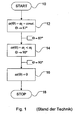
- FIG. 1 shows a flowchart for a braking method according to the prior art.
- the braking program is started in step 10.
- the rotor blade is adjusted at constant angular velocity ⁇ 1 in the direction of the feathering position. From a blade pitch angle ⁇ of approximately 87 °, the adjustment of the rotor blade until reaching the feathering position according to step 14 takes place with a lower angular velocity ⁇ x ⁇ 1 . After reaching the end position of the rotor blade at approximately 90 °, the angular velocity ⁇ is lowered to the value 0 in step 16 and the braking program is terminated in step 18.
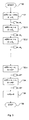
- FIG. 3 shows a flowchart for the inventive method.
- the braking program is started. This may be done, for example, in response to a signal for emergency braking.
- the rotor blade is driven at a constant angular velocity ⁇ 1 until reaching a first defined angular position ⁇ 1 in the direction of the feathering position.
- the adjustment of the rotor blade until reaching the feathering position according to step 34 takes place at a lower angular velocity ⁇ x .
- the angular velocity ⁇ is lowered to the value 0 in step 36 and the braking program is terminated in step 38.
- FIGS. 4 a and b show the time course of the sheet adjustment speed ⁇ and the sheet adjustment angle ⁇ after the in FIG. 3 described method.
- the same boundary conditions as in the example from the prior art are assumed.
- the brake program is triggered.
- the rotor blade is adjusted at a first constant angular velocity ⁇ 1 .
- the rotor blade reaches a setting angle ⁇ of approximately 87 °.
- the angular velocity U1 is lowered to a value ⁇ x smaller than ⁇ n .
- FIG. 5 shows a flowchart for an extended variant of the method according to the invention.
- the braking program is started in step 50.
- step 52 a query of the current sheet pitch ⁇ . If the value of the current blade adjustment angle ⁇ is greater than or equal to a predetermined blade adjustment angle ⁇ 0 , the braking program runs according to the method according to the invention in accordance with step 56. If the current sheet pitch angle ⁇ is smaller than the predetermined sheet pitch angle ⁇ 0 , the sheet is adjusted in step 54 with an angular velocity ⁇ 10 , where ⁇ 10 is greater than the angular velocity ⁇ 1 with which the brake program according to the invention is started. The amount of angular velocity ⁇ 10 may be constant or decreased stepwise. After reaching a predetermined blade pitch angle ⁇ 0 , the braking program is continued in step 56 with the inventive method and ends after reaching the flag position in step 58.
- FIGS. 6 a and b show the time course of the sheet adjustment speed ⁇ and the sheet adjustment angle ⁇ after the in FIG. 5 described method.
- the wind turbine is in production at rated power, with the blade pitch ⁇ is about 10 °.
- a gust hits the wind energy plant and the rotor blade is adjusted to adapt the rotational speed to a blade pitch angle ⁇ A.
- a load shedding occurs and the generator speed increases to a value above the rated speed. This speed increase triggers the brake program.
Landscapes
- Engineering & Computer Science (AREA)
- Life Sciences & Earth Sciences (AREA)
- Sustainable Development (AREA)
- Sustainable Energy (AREA)
- Chemical & Material Sciences (AREA)
- Combustion & Propulsion (AREA)
- Mechanical Engineering (AREA)
- General Engineering & Computer Science (AREA)
- Physics & Mathematics (AREA)
- Fluid Mechanics (AREA)
- Wind Motors (AREA)
Claims (13)
- Procédé de freinage d'urgence d'une éolienne, dans lequel au moins une pale de rotor de l'éolienne est déplacée pour être mise en drapeau, le procédé présentant les étapes suivantes :- une première phase dans laquelle au moins une pale de rotor est déplacée à une première vitesse (ω1), et- une deuxième phase dans laquelle au moins une pale de rotor est déplacée à une deuxième vitesse (ω2, ω3...) à partir d'un premier angle de réglage de pale (Θ1) prédéfini, indépendamment d'une déviation d'une tête de tour de l'éolienne,caractérisé en ce que la deuxième vitesse (ω2, ω3...) est plus élevée que la première vitesse (ω1) et est augmentée en continu ou bien graduellement jusqu'à l'obtention d'une vitesse maximale et/ou jusqu'à l'obtention d'un deuxième angle de réglage de pale (Θ2) prédéfini.
- Procédé selon la revendication 1, caractérisé en ce que la première vitesse (ω1) est constante dans la première phase.
- Procédé selon la revendication 1 ou 2, caractérisé en ce que le premier angle de réglage de pale (Θ1) prédéfini se situe dans une plage dans laquelle il apparaît des charges quantitativement plus faibles sur la pale de rotor qu'au début de processus de déplacement.
- Procédé selon une des revendications 1 à 3, caractérisé en ce que le premier angle de réglage de pale (Θ1) prédéfini présente une valeur de 30° à 50°.
- Procédé selon une des revendications 1 à 4, caractérisé en ce que, à partir d'un troisième angle de réglage de pale (Θ3) prédéfini qui est plus petit que le premier angle de réglage de pale (Θ1) prédéfini, la vitesse du déplacement de la pale de rotor est abaissée dans une troisième phase.
- Procédé selon la revendication 5, caractérisé en ce que le troisième angle de réglage de pale (Θ3) prédéfini est inférieur de 10° à 20° au premier angle de réglage de pale (Θ1) prédéfini.
- Eolienne avec au moins une pale de rotor et au moins un dispositif de déplacement de pale de rotor qui peut régler pour au moins une pale de rotor l'angle de réglage de pale (Θ) et qui, en réaction à un signal de commande pour un freinage d'urgence, peut déplacer au moins une pale de rotor pour la mettre en drapeau, le dispositif de déplacement de pale de rotor déplaçant, dans une première phase, la pale de rotor à une première vitesse (ω1) lors de la mise en drapeau de la pale de rotor au moins au nombre de un et, à partir d'un premier angle de réglage de pale (Θ1) prédéfini, déplaçant, dans une deuxième phase, à une deuxième vitesse (ω2, ω3...) la pale de rotor indépendamment d'une déviation d'une tête de tour de l'éolienne, caractérisée en ce que la deuxième vitesse (ω2, ω3...) est plus élevée que la première vitesse (ω1) et est augmentée en continu ou bien graduellement jusqu'à l'obtention d'une vitesse maximale et/ou jusqu'à l'obtention d'un deuxième angle de réglage de pale (Θ2) prédéfini.
- Eolienne selon la revendication 7, caractérisée en ce que la première vitesse (ω1) est constante dans la première phase.
- Eolienne selon la revendication 7 ou 8, caractérisée en ce que le premier angle de réglage de pale (Θ1) prédéfini se situe dans une plage à partir de laquelle il faut s'attendre à des charges quantitativement plus faibles sur la pale de rotor, en particulier entre 30° et 50°.
- Eolienne selon une des revendications 7 à 9, caractérisée en ce que le dispositif de déplacement de pale de rotor, à partir d'un troisième angle de réglage de pale (Θ3) prédéfini qui est plus petit que le premier angle de réglage de pale (Θ1) prédéfini, abaisse la vitesse de déplacement de la pale de rotor dans une troisième phase.
- Eolienne selon la revendication 10, caractérisée en ce que, dans la troisième phase, on est en présence d'une vitesse constante.
- Eolienne selon la revendication 10 ou 11, caractérisée en ce que le troisième angle de réglage de pale (Θ3) prédéfini est inférieur de 10° à 20° au premier angle de réglage de pale (Θ1) prédéfini.
- Eolienne selon une des revendications 7 à 12, caractérisée en ce que le dispositif de déplacement de pale de rotor réduit la vitesse lors de l'obtention du deuxième angle de réglage de pale (Θ2) prédéfini.
Priority Applications (2)
| Application Number | Priority Date | Filing Date | Title |
|---|---|---|---|
| EP09007124.2A EP2256342B8 (fr) | 2009-05-28 | 2009-05-28 | Procédé de freinage d'urgence d'une éolienne et éolienne dotée d'un réglage de pale de rotor pour le freinage d'urgence |
| US12/504,778 US8348617B2 (en) | 2009-05-28 | 2009-07-17 | Method for the emergency braking of a wind power plant and a wind power plant with a rotor blade pitch control for emergency braking |
Applications Claiming Priority (1)
| Application Number | Priority Date | Filing Date | Title |
|---|---|---|---|
| EP09007124.2A EP2256342B8 (fr) | 2009-05-28 | 2009-05-28 | Procédé de freinage d'urgence d'une éolienne et éolienne dotée d'un réglage de pale de rotor pour le freinage d'urgence |
Publications (3)
| Publication Number | Publication Date |
|---|---|
| EP2256342A1 EP2256342A1 (fr) | 2010-12-01 |
| EP2256342B1 true EP2256342B1 (fr) | 2013-09-18 |
| EP2256342B8 EP2256342B8 (fr) | 2013-10-23 |
Family
ID=41361319
Family Applications (1)
| Application Number | Title | Priority Date | Filing Date |
|---|---|---|---|
| EP09007124.2A Active EP2256342B8 (fr) | 2009-05-28 | 2009-05-28 | Procédé de freinage d'urgence d'une éolienne et éolienne dotée d'un réglage de pale de rotor pour le freinage d'urgence |
Country Status (2)
| Country | Link |
|---|---|
| US (1) | US8348617B2 (fr) |
| EP (1) | EP2256342B8 (fr) |
Cited By (1)
| Publication number | Priority date | Publication date | Assignee | Title |
|---|---|---|---|---|
| EP2876300B1 (fr) | 2013-11-25 | 2021-12-29 | General Electric Company | Procédés et systèmes pour éteindre une turbine éolienne |
Families Citing this family (6)
| Publication number | Priority date | Publication date | Assignee | Title |
|---|---|---|---|---|
| WO2013159779A1 (fr) | 2012-04-23 | 2013-10-31 | Vestas Wind Systems A/S | Procédé de commande d'une turbine éolienne pendant un arrêt |
| EP2844870B1 (fr) * | 2012-05-02 | 2020-07-01 | General Electric Company | Système et méthode d'arrêt du fonctionnement d'une turbine éolienne |
| CN103352798B (zh) * | 2013-06-26 | 2015-07-15 | 国家电网公司 | 一种风电机组收桨系统及收桨方法 |
| KR102042259B1 (ko) * | 2013-08-14 | 2019-11-07 | 두산중공업 주식회사 | 풍력발전시스템 및 그것의 구동 정지 방법 |
| JP6462388B2 (ja) * | 2015-02-06 | 2019-01-30 | 株式会社日立製作所 | 風力発電装置 |
| CN109139372B (zh) * | 2018-08-06 | 2020-01-10 | 大连理工大学 | 一种基于独立变桨的风电机组控制和制动方法 |
Family Cites Families (6)
| Publication number | Priority date | Publication date | Assignee | Title |
|---|---|---|---|---|
| US4462753A (en) * | 1982-06-22 | 1984-07-31 | United Technologies Corporation | Blade feathering system for wind turbines |
| FI117352B (fi) | 2005-03-09 | 2006-09-15 | Winwind Oy | Menetelmä tuulivoimalan roottorin pysäyttämiseksi |
| DE102005034899A1 (de) | 2005-07-26 | 2007-02-01 | Repower Systems Ag | Windenergieanlage mit Einzelpitcheinrichtungen |
| US7488155B2 (en) | 2005-11-18 | 2009-02-10 | General Electric Company | Method and apparatus for wind turbine braking |
| DE102006001613B4 (de) * | 2006-01-11 | 2008-01-31 | Repower Systems Ag | Verfahren zum Betreiben einer Windenergieanlage und Windenergieanlage |
| WO2009010059A2 (fr) | 2007-07-14 | 2009-01-22 | Vestas Wind Systems A/S | Commande d'un rotor pendant un processus d'arrêt d'une éolienne |
-
2009
- 2009-05-28 EP EP09007124.2A patent/EP2256342B8/fr active Active
- 2009-07-17 US US12/504,778 patent/US8348617B2/en active Active
Cited By (1)
| Publication number | Priority date | Publication date | Assignee | Title |
|---|---|---|---|---|
| EP2876300B1 (fr) | 2013-11-25 | 2021-12-29 | General Electric Company | Procédés et systèmes pour éteindre une turbine éolienne |
Also Published As
| Publication number | Publication date |
|---|---|
| EP2256342B8 (fr) | 2013-10-23 |
| US8348617B2 (en) | 2013-01-08 |
| EP2256342A1 (fr) | 2010-12-01 |
| US20100303622A1 (en) | 2010-12-02 |
Similar Documents
| Publication | Publication Date | Title |
|---|---|---|
| EP2256342B1 (fr) | Procédé de freinage d'urgence d'une éolienne et éolienne dotée d'un réglage de pale de rotor pour le freinage d'urgence | |
| DE10058076C2 (de) | Verfahren zur Steuerung einer Windenergieanlage | |
| DE60218328T2 (de) | Rotor mit teleskopischem blättern und steuerungskriterien | |
| DE102006001613B4 (de) | Verfahren zum Betreiben einer Windenergieanlage und Windenergieanlage | |
| DE10106208C2 (de) | Windenergieanlage | |
| EP1286049B1 (fr) | Eolienne | |
| EP2217805B1 (fr) | Dispositif de commande pour des installations éoliennes comportant un système de détection de panne de secteur | |
| DE102004024564B4 (de) | Verfahren zur Steuerung und Regelung einer Windenergieanlage sowie Windenergieanlage | |
| EP3735532B1 (fr) | Fonctionnement d'une éolienne en cas de tempête | |
| DE102010031081A1 (de) | Windenergieanlage | |
| EP2063109A2 (fr) | Procédé de commande d'une éolienne | |
| EP2923079B1 (fr) | Procédé pour faire fonctionner une éolienne et éolienne | |
| EP3857051A1 (fr) | Procédé pour faire fonctionner une éolienne, éolienne et parc éolien | |
| EP3489507B1 (fr) | Procédé et dispositif destinés au fonctionnement d'une éolienne | |
| EP3926162A1 (fr) | Procédé de fonctionnement d'une éolienne, dispositif de commande destiné au fonctionnement d'un éolienne et parc éolien | |
| EP2948678B1 (fr) | Procédé de réglage azimutal d'une éolienne, système de réglage azimutal et éolienne | |
| EP3768970B1 (fr) | Procédé pour faire fonctionner une éolienne, éolienne et parc éolien | |
| EP3981981A1 (fr) | Pale de rotor pour une éolienne, éolienne et procédé de conception d'une pale de rotor | |
| EP3165765B1 (fr) | Procédé et système de commande d'un angle d'attaque d'une pale de rotor et éolienne et procédé de fonctionnement d'une éolienne | |
| EP3839249B1 (fr) | Procede de reglage de l'angle de pas d'une pale de rotor, dispositif de commande pour regler l'angle de pas, et eolienne correspondante | |
| EP4148270B1 (fr) | Procédé d'ajustement d'une courbe caractéristique de fonctionnement d'une éolienne | |
| WO2010075833A2 (fr) | Éolienne | |
| WO2024094764A1 (fr) | Dispositif et procédé pour positionner une pièce mobile dans une position de consigne par rapport à un fluide en écoulement |
Legal Events
| Date | Code | Title | Description |
|---|---|---|---|
| PUAI | Public reference made under article 153(3) epc to a published international application that has entered the european phase |
Free format text: ORIGINAL CODE: 0009012 |
|
| AK | Designated contracting states |
Kind code of ref document: A1 Designated state(s): AT BE BG CH CY CZ DE DK EE ES FI FR GB GR HR HU IE IS IT LI LT LU LV MC MK MT NL NO PL PT RO SE SI SK TR |
|
| AX | Request for extension of the european patent |
Extension state: AL BA RS |
|
| 17P | Request for examination filed |
Effective date: 20110514 |
|
| 17Q | First examination report despatched |
Effective date: 20110617 |
|
| GRAP | Despatch of communication of intention to grant a patent |
Free format text: ORIGINAL CODE: EPIDOSNIGR1 |
|
| INTG | Intention to grant announced |
Effective date: 20130415 |
|
| GRAS | Grant fee paid |
Free format text: ORIGINAL CODE: EPIDOSNIGR3 |
|
| GRAA | (expected) grant |
Free format text: ORIGINAL CODE: 0009210 |
|
| AK | Designated contracting states |
Kind code of ref document: B1 Designated state(s): AT BE BG CH CY CZ DE DK EE ES FI FR GB GR HR HU IE IS IT LI LT LU LV MC MK MT NL NO PL PT RO SE SI SK TR |
|
| REG | Reference to a national code |
Ref country code: GB Ref legal event code: FG4D Free format text: NOT ENGLISH |
|
| REG | Reference to a national code |
Ref country code: CH Ref legal event code: EP |
|
| REG | Reference to a national code |
Ref country code: IE Ref legal event code: FG4D Free format text: LANGUAGE OF EP DOCUMENT: GERMAN |
|
| REG | Reference to a national code |
Ref country code: AT Ref legal event code: REF Ref document number: 632940 Country of ref document: AT Kind code of ref document: T Effective date: 20131015 |
|
| RAP2 | Party data changed (patent owner data changed or rights of a patent transferred) |
Owner name: NORDEX ENERGY GMBH |
|
| REG | Reference to a national code |
Ref country code: DE Ref legal event code: R096 Ref document number: 502009008021 Country of ref document: DE Effective date: 20131114 |
|
| REG | Reference to a national code |
Ref country code: DE Ref legal event code: R081 Ref document number: 502009008021 Country of ref document: DE Owner name: NORDEX ENERGY GMBH, DE Free format text: FORMER OWNER: NORDEX ENERGY GMBH, 22848 NORDERSTEDT, DE Effective date: 20131029 |
|
| REG | Reference to a national code |
Ref country code: SE Ref legal event code: TRGR |
|
| PG25 | Lapsed in a contracting state [announced via postgrant information from national office to epo] |
Ref country code: LT Free format text: LAPSE BECAUSE OF FAILURE TO SUBMIT A TRANSLATION OF THE DESCRIPTION OR TO PAY THE FEE WITHIN THE PRESCRIBED TIME-LIMIT Effective date: 20130918 Ref country code: HR Free format text: LAPSE BECAUSE OF FAILURE TO SUBMIT A TRANSLATION OF THE DESCRIPTION OR TO PAY THE FEE WITHIN THE PRESCRIBED TIME-LIMIT Effective date: 20130918 Ref country code: NO Free format text: LAPSE BECAUSE OF FAILURE TO SUBMIT A TRANSLATION OF THE DESCRIPTION OR TO PAY THE FEE WITHIN THE PRESCRIBED TIME-LIMIT Effective date: 20131218 Ref country code: CY Free format text: LAPSE BECAUSE OF FAILURE TO SUBMIT A TRANSLATION OF THE DESCRIPTION OR TO PAY THE FEE WITHIN THE PRESCRIBED TIME-LIMIT Effective date: 20130911 |
|
| REG | Reference to a national code |
Ref country code: NL Ref legal event code: VDEP Effective date: 20130918 |
|
| REG | Reference to a national code |
Ref country code: LT Ref legal event code: MG4D |
|
| PG25 | Lapsed in a contracting state [announced via postgrant information from national office to epo] |
Ref country code: LV Free format text: LAPSE BECAUSE OF FAILURE TO SUBMIT A TRANSLATION OF THE DESCRIPTION OR TO PAY THE FEE WITHIN THE PRESCRIBED TIME-LIMIT Effective date: 20130918 Ref country code: FI Free format text: LAPSE BECAUSE OF FAILURE TO SUBMIT A TRANSLATION OF THE DESCRIPTION OR TO PAY THE FEE WITHIN THE PRESCRIBED TIME-LIMIT Effective date: 20130918 Ref country code: SI Free format text: LAPSE BECAUSE OF FAILURE TO SUBMIT A TRANSLATION OF THE DESCRIPTION OR TO PAY THE FEE WITHIN THE PRESCRIBED TIME-LIMIT Effective date: 20130918 Ref country code: GR Free format text: LAPSE BECAUSE OF FAILURE TO SUBMIT A TRANSLATION OF THE DESCRIPTION OR TO PAY THE FEE WITHIN THE PRESCRIBED TIME-LIMIT Effective date: 20131219 |
|
| PG25 | Lapsed in a contracting state [announced via postgrant information from national office to epo] |
Ref country code: CY Free format text: LAPSE BECAUSE OF FAILURE TO SUBMIT A TRANSLATION OF THE DESCRIPTION OR TO PAY THE FEE WITHIN THE PRESCRIBED TIME-LIMIT Effective date: 20130918 |
|
| PG25 | Lapsed in a contracting state [announced via postgrant information from national office to epo] |
Ref country code: IS Free format text: LAPSE BECAUSE OF FAILURE TO SUBMIT A TRANSLATION OF THE DESCRIPTION OR TO PAY THE FEE WITHIN THE PRESCRIBED TIME-LIMIT Effective date: 20140118 Ref country code: NL Free format text: LAPSE BECAUSE OF FAILURE TO SUBMIT A TRANSLATION OF THE DESCRIPTION OR TO PAY THE FEE WITHIN THE PRESCRIBED TIME-LIMIT Effective date: 20130918 Ref country code: CZ Free format text: LAPSE BECAUSE OF FAILURE TO SUBMIT A TRANSLATION OF THE DESCRIPTION OR TO PAY THE FEE WITHIN THE PRESCRIBED TIME-LIMIT Effective date: 20130918 Ref country code: EE Free format text: LAPSE BECAUSE OF FAILURE TO SUBMIT A TRANSLATION OF THE DESCRIPTION OR TO PAY THE FEE WITHIN THE PRESCRIBED TIME-LIMIT Effective date: 20130918 Ref country code: SK Free format text: LAPSE BECAUSE OF FAILURE TO SUBMIT A TRANSLATION OF THE DESCRIPTION OR TO PAY THE FEE WITHIN THE PRESCRIBED TIME-LIMIT Effective date: 20130918 Ref country code: RO Free format text: LAPSE BECAUSE OF FAILURE TO SUBMIT A TRANSLATION OF THE DESCRIPTION OR TO PAY THE FEE WITHIN THE PRESCRIBED TIME-LIMIT Effective date: 20130918 |
|
| PG25 | Lapsed in a contracting state [announced via postgrant information from national office to epo] |
Ref country code: ES Free format text: LAPSE BECAUSE OF FAILURE TO SUBMIT A TRANSLATION OF THE DESCRIPTION OR TO PAY THE FEE WITHIN THE PRESCRIBED TIME-LIMIT Effective date: 20130918 Ref country code: PL Free format text: LAPSE BECAUSE OF FAILURE TO SUBMIT A TRANSLATION OF THE DESCRIPTION OR TO PAY THE FEE WITHIN THE PRESCRIBED TIME-LIMIT Effective date: 20130918 |
|
| PLBI | Opposition filed |
Free format text: ORIGINAL CODE: 0009260 |
|
| PG25 | Lapsed in a contracting state [announced via postgrant information from national office to epo] |
Ref country code: PT Free format text: LAPSE BECAUSE OF FAILURE TO SUBMIT A TRANSLATION OF THE DESCRIPTION OR TO PAY THE FEE WITHIN THE PRESCRIBED TIME-LIMIT Effective date: 20140120 |
|
| 26 | Opposition filed |
Opponent name: ENERCON GMBH Effective date: 20140618 |
|
| PLAX | Notice of opposition and request to file observation + time limit sent |
Free format text: ORIGINAL CODE: EPIDOSNOBS2 |
|
| REG | Reference to a national code |
Ref country code: DE Ref legal event code: R026 Ref document number: 502009008021 Country of ref document: DE Effective date: 20140618 |
|
| PG25 | Lapsed in a contracting state [announced via postgrant information from national office to epo] |
Ref country code: IT Free format text: LAPSE BECAUSE OF FAILURE TO SUBMIT A TRANSLATION OF THE DESCRIPTION OR TO PAY THE FEE WITHIN THE PRESCRIBED TIME-LIMIT Effective date: 20130918 |
|
| PG25 | Lapsed in a contracting state [announced via postgrant information from national office to epo] |
Ref country code: DK Free format text: LAPSE BECAUSE OF FAILURE TO SUBMIT A TRANSLATION OF THE DESCRIPTION OR TO PAY THE FEE WITHIN THE PRESCRIBED TIME-LIMIT Effective date: 20130918 |
|
| PLAF | Information modified related to communication of a notice of opposition and request to file observations + time limit |
Free format text: ORIGINAL CODE: EPIDOSCOBS2 |
|
| PG25 | Lapsed in a contracting state [announced via postgrant information from national office to epo] |
Ref country code: LU Free format text: LAPSE BECAUSE OF FAILURE TO SUBMIT A TRANSLATION OF THE DESCRIPTION OR TO PAY THE FEE WITHIN THE PRESCRIBED TIME-LIMIT Effective date: 20140528 |
|
| REG | Reference to a national code |
Ref country code: CH Ref legal event code: PL |
|
| PG25 | Lapsed in a contracting state [announced via postgrant information from national office to epo] |
Ref country code: LI Free format text: LAPSE BECAUSE OF NON-PAYMENT OF DUE FEES Effective date: 20140531 Ref country code: MC Free format text: LAPSE BECAUSE OF FAILURE TO SUBMIT A TRANSLATION OF THE DESCRIPTION OR TO PAY THE FEE WITHIN THE PRESCRIBED TIME-LIMIT Effective date: 20130918 Ref country code: CH Free format text: LAPSE BECAUSE OF NON-PAYMENT OF DUE FEES Effective date: 20140531 |
|
| PLBB | Reply of patent proprietor to notice(s) of opposition received |
Free format text: ORIGINAL CODE: EPIDOSNOBS3 |
|
| REG | Reference to a national code |
Ref country code: IE Ref legal event code: MM4A |
|
| PG25 | Lapsed in a contracting state [announced via postgrant information from national office to epo] |
Ref country code: IE Free format text: LAPSE BECAUSE OF NON-PAYMENT OF DUE FEES Effective date: 20140528 |
|
| REG | Reference to a national code |
Ref country code: AT Ref legal event code: MM01 Ref document number: 632940 Country of ref document: AT Kind code of ref document: T Effective date: 20140528 |
|
| PG25 | Lapsed in a contracting state [announced via postgrant information from national office to epo] |
Ref country code: AT Free format text: LAPSE BECAUSE OF NON-PAYMENT OF DUE FEES Effective date: 20140528 |
|
| PG25 | Lapsed in a contracting state [announced via postgrant information from national office to epo] |
Ref country code: MT Free format text: LAPSE BECAUSE OF FAILURE TO SUBMIT A TRANSLATION OF THE DESCRIPTION OR TO PAY THE FEE WITHIN THE PRESCRIBED TIME-LIMIT Effective date: 20130918 |
|
| REG | Reference to a national code |
Ref country code: FR Ref legal event code: PLFP Year of fee payment: 8 |
|
| PG25 | Lapsed in a contracting state [announced via postgrant information from national office to epo] |
Ref country code: BG Free format text: LAPSE BECAUSE OF FAILURE TO SUBMIT A TRANSLATION OF THE DESCRIPTION OR TO PAY THE FEE WITHIN THE PRESCRIBED TIME-LIMIT Effective date: 20130918 |
|
| PG25 | Lapsed in a contracting state [announced via postgrant information from national office to epo] |
Ref country code: TR Free format text: LAPSE BECAUSE OF FAILURE TO SUBMIT A TRANSLATION OF THE DESCRIPTION OR TO PAY THE FEE WITHIN THE PRESCRIBED TIME-LIMIT Effective date: 20130918 Ref country code: BE Free format text: LAPSE BECAUSE OF FAILURE TO SUBMIT A TRANSLATION OF THE DESCRIPTION OR TO PAY THE FEE WITHIN THE PRESCRIBED TIME-LIMIT Effective date: 20140531 Ref country code: HU Free format text: LAPSE BECAUSE OF FAILURE TO SUBMIT A TRANSLATION OF THE DESCRIPTION OR TO PAY THE FEE WITHIN THE PRESCRIBED TIME-LIMIT; INVALID AB INITIO Effective date: 20090528 |
|
| PLBP | Opposition withdrawn |
Free format text: ORIGINAL CODE: 0009264 |
|
| PLBD | Termination of opposition procedure: decision despatched |
Free format text: ORIGINAL CODE: EPIDOSNOPC1 |
|
| REG | Reference to a national code |
Ref country code: DE Ref legal event code: R100 Ref document number: 502009008021 Country of ref document: DE |
|
| REG | Reference to a national code |
Ref country code: FR Ref legal event code: PLFP Year of fee payment: 9 |
|
| PLBM | Termination of opposition procedure: date of legal effect published |
Free format text: ORIGINAL CODE: 0009276 |
|
| STAA | Information on the status of an ep patent application or granted ep patent |
Free format text: STATUS: OPPOSITION PROCEDURE CLOSED |
|
| 27C | Opposition proceedings terminated |
Effective date: 20170224 |
|
| REG | Reference to a national code |
Ref country code: FR Ref legal event code: PLFP Year of fee payment: 10 |
|
| PG25 | Lapsed in a contracting state [announced via postgrant information from national office to epo] |
Ref country code: MK Free format text: LAPSE BECAUSE OF FAILURE TO SUBMIT A TRANSLATION OF THE DESCRIPTION OR TO PAY THE FEE WITHIN THE PRESCRIBED TIME-LIMIT Effective date: 20130918 |
|
| REG | Reference to a national code |
Ref country code: DE Ref legal event code: R082 Ref document number: 502009008021 Country of ref document: DE Representative=s name: HAUCK PATENTANWALTSPARTNERSCHAFT MBB, DE Ref country code: DE Ref legal event code: R081 Ref document number: 502009008021 Country of ref document: DE Owner name: NORDEX ENERGY SE & CO. KG, DE Free format text: FORMER OWNER: NORDEX ENERGY GMBH, 22419 HAMBURG, DE |
|
| P01 | Opt-out of the competence of the unified patent court (upc) registered |
Effective date: 20230602 |
|
| PGFP | Annual fee paid to national office [announced via postgrant information from national office to epo] |
Ref country code: DE Payment date: 20250519 Year of fee payment: 17 |
|
| PGFP | Annual fee paid to national office [announced via postgrant information from national office to epo] |
Ref country code: FR Payment date: 20250521 Year of fee payment: 17 |
|
| PGFP | Annual fee paid to national office [announced via postgrant information from national office to epo] |
Ref country code: SE Payment date: 20250522 Year of fee payment: 17 |
|
| PGFP | Annual fee paid to national office [announced via postgrant information from national office to epo] |
Ref country code: GB Payment date: 20260324 Year of fee payment: 18 |