EP2259157A2 - Mouvement horloger pour montre bracelet - Google Patents
Mouvement horloger pour montre bracelet Download PDFInfo
- Publication number
- EP2259157A2 EP2259157A2 EP10180522A EP10180522A EP2259157A2 EP 2259157 A2 EP2259157 A2 EP 2259157A2 EP 10180522 A EP10180522 A EP 10180522A EP 10180522 A EP10180522 A EP 10180522A EP 2259157 A2 EP2259157 A2 EP 2259157A2
- Authority
- EP
- European Patent Office
- Prior art keywords
- belt
- watch
- movement
- movement according
- belts
- Prior art date
- Legal status (The legal status is an assumption and is not a legal conclusion. Google has not performed a legal analysis and makes no representation as to the accuracy of the status listed.)
- Granted
Links
- 230000033001 locomotion Effects 0.000 claims abstract description 90
- 229910052751 metal Inorganic materials 0.000 claims abstract description 5
- 239000002184 metal Substances 0.000 claims abstract description 5
- 229920002994 synthetic fiber Polymers 0.000 claims abstract description 5
- 239000000758 substrate Substances 0.000 claims abstract description 3
- 230000005540 biological transmission Effects 0.000 abstract description 4
- 238000004519 manufacturing process Methods 0.000 abstract description 4
- 230000037431 insertion Effects 0.000 abstract 1
- 238000003780 insertion Methods 0.000 abstract 1
- 238000000465 moulding Methods 0.000 abstract 1
- 210000000707 wrist Anatomy 0.000 description 7
- 210000004247 hand Anatomy 0.000 description 6
- 230000001105 regulatory effect Effects 0.000 description 6
- BASFCYQUMIYNBI-UHFFFAOYSA-N platinum Chemical compound [Pt] BASFCYQUMIYNBI-UHFFFAOYSA-N 0.000 description 5
- 238000006073 displacement reaction Methods 0.000 description 4
- 230000000694 effects Effects 0.000 description 4
- 238000004804 winding Methods 0.000 description 4
- 230000035939 shock Effects 0.000 description 3
- 230000001133 acceleration Effects 0.000 description 2
- 239000011521 glass Substances 0.000 description 2
- 229910052697 platinum Inorganic materials 0.000 description 2
- PEDCQBHIVMGVHV-UHFFFAOYSA-N Glycerine Chemical compound OCC(O)CO PEDCQBHIVMGVHV-UHFFFAOYSA-N 0.000 description 1
- 230000002457 bidirectional effect Effects 0.000 description 1
- 210000004027 cell Anatomy 0.000 description 1
- 238000010276 construction Methods 0.000 description 1
- 239000013078 crystal Substances 0.000 description 1
- 210000002858 crystal cell Anatomy 0.000 description 1
- 238000009826 distribution Methods 0.000 description 1
- 238000005516 engineering process Methods 0.000 description 1
- 238000004880 explosion Methods 0.000 description 1
- 230000005484 gravity Effects 0.000 description 1
- 230000008595 infiltration Effects 0.000 description 1
- 238000001764 infiltration Methods 0.000 description 1
- 239000004973 liquid crystal related substance Substances 0.000 description 1
- 238000005461 lubrication Methods 0.000 description 1
- 239000000463 material Substances 0.000 description 1
- 238000000034 method Methods 0.000 description 1
- 238000012986 modification Methods 0.000 description 1
- 230000004048 modification Effects 0.000 description 1
- 230000010355 oscillation Effects 0.000 description 1
- 239000010453 quartz Substances 0.000 description 1
- VYPSYNLAJGMNEJ-UHFFFAOYSA-N silicon dioxide Inorganic materials O=[Si]=O VYPSYNLAJGMNEJ-UHFFFAOYSA-N 0.000 description 1
- 235000019640 taste Nutrition 0.000 description 1
Images


Classifications
-
- G—PHYSICS
- G04—HOROLOGY
- G04B—MECHANICALLY-DRIVEN CLOCKS OR WATCHES; MECHANICAL PARTS OF CLOCKS OR WATCHES IN GENERAL; TIME PIECES USING THE POSITION OF THE SUN, MOON OR STARS
- G04B1/00—Driving mechanisms
-
- G—PHYSICS
- G04—HOROLOGY
- G04B—MECHANICALLY-DRIVEN CLOCKS OR WATCHES; MECHANICAL PARTS OF CLOCKS OR WATCHES IN GENERAL; TIME PIECES USING THE POSITION OF THE SUN, MOON OR STARS
- G04B1/00—Driving mechanisms
- G04B1/10—Driving mechanisms with mainspring
- G04B1/12—Driving mechanisms with mainspring with several mainsprings
-
- G—PHYSICS
- G04—HOROLOGY
- G04B—MECHANICALLY-DRIVEN CLOCKS OR WATCHES; MECHANICAL PARTS OF CLOCKS OR WATCHES IN GENERAL; TIME PIECES USING THE POSITION OF THE SUN, MOON OR STARS
- G04B19/00—Indicating the time by visual means
- G04B19/04—Hands; Discs with a single mark or the like
-
- G—PHYSICS
- G04—HOROLOGY
- G04B—MECHANICALLY-DRIVEN CLOCKS OR WATCHES; MECHANICAL PARTS OF CLOCKS OR WATCHES IN GENERAL; TIME PIECES USING THE POSITION OF THE SUN, MOON OR STARS
- G04B19/00—Indicating the time by visual means
- G04B19/20—Indicating by numbered bands, drums, discs, or sheets
-
- G—PHYSICS
- G04—HOROLOGY
- G04B—MECHANICALLY-DRIVEN CLOCKS OR WATCHES; MECHANICAL PARTS OF CLOCKS OR WATCHES IN GENERAL; TIME PIECES USING THE POSITION OF THE SUN, MOON OR STARS
- G04B19/00—Indicating the time by visual means
- G04B19/20—Indicating by numbered bands, drums, discs, or sheets
- G04B19/207—Indicating by numbered bands, drums, discs, or sheets by means of bands
-
- G—PHYSICS
- G04—HOROLOGY
- G04B—MECHANICALLY-DRIVEN CLOCKS OR WATCHES; MECHANICAL PARTS OF CLOCKS OR WATCHES IN GENERAL; TIME PIECES USING THE POSITION OF THE SUN, MOON OR STARS
- G04B37/00—Cases
- G04B37/0008—Cases for pocket watches and wrist watches
- G04B37/0058—Cases for pocket watches and wrist watches for shaped watches
-
- G—PHYSICS
- G04—HOROLOGY
- G04B—MECHANICALLY-DRIVEN CLOCKS OR WATCHES; MECHANICAL PARTS OF CLOCKS OR WATCHES IN GENERAL; TIME PIECES USING THE POSITION OF THE SUN, MOON OR STARS
- G04B37/00—Cases
- G04B37/08—Hermetic sealing of openings, joints, passages or slits
- G04B37/081—Complete encasings for wrist or pocket watches also comprising means for hermetic sealing of the winding stem and crown
- G04B37/083—Complete encasings for wrist or pocket watches also comprising means for hermetic sealing of the winding stem and crown for shaped watches
-
- G—PHYSICS
- G04—HOROLOGY
- G04B—MECHANICALLY-DRIVEN CLOCKS OR WATCHES; MECHANICAL PARTS OF CLOCKS OR WATCHES IN GENERAL; TIME PIECES USING THE POSITION OF THE SUN, MOON OR STARS
- G04B45/00—Time pieces of which the indicating means or cases provoke special effects, e.g. aesthetic effects
- G04B45/0069—Cases and fixed parts with a special shape
-
- G—PHYSICS
- G04—HOROLOGY
- G04B—MECHANICALLY-DRIVEN CLOCKS OR WATCHES; MECHANICAL PARTS OF CLOCKS OR WATCHES IN GENERAL; TIME PIECES USING THE POSITION OF THE SUN, MOON OR STARS
- G04B45/00—Time pieces of which the indicating means or cases provoke special effects, e.g. aesthetic effects
- G04B45/02—Time pieces of which the clockwork is visible partly or wholly
-
- G—PHYSICS
- G04—HOROLOGY
- G04B—MECHANICALLY-DRIVEN CLOCKS OR WATCHES; MECHANICAL PARTS OF CLOCKS OR WATCHES IN GENERAL; TIME PIECES USING THE POSITION OF THE SUN, MOON OR STARS
- G04B5/00—Automatic winding up
- G04B5/02—Automatic winding up by self-winding caused by the movement of the watch
- G04B5/04—Automatic winding up by self-winding caused by the movement of the watch by oscillating weights the movement of which is limited
- G04B5/08—Automatic winding up by self-winding caused by the movement of the watch by oscillating weights the movement of which is limited acting in both directions
-
- G—PHYSICS
- G04—HOROLOGY
- G04B—MECHANICALLY-DRIVEN CLOCKS OR WATCHES; MECHANICAL PARTS OF CLOCKS OR WATCHES IN GENERAL; TIME PIECES USING THE POSITION OF THE SUN, MOON OR STARS
- G04B5/00—Automatic winding up
- G04B5/02—Automatic winding up by self-winding caused by the movement of the watch
- G04B5/18—Supports, suspensions or guide arrangements, for oscillating weights
- G04B5/182—Guide arrangement of the moving weight in a straight course
-
- B—PERFORMING OPERATIONS; TRANSPORTING
- B29—WORKING OF PLASTICS; WORKING OF SUBSTANCES IN A PLASTIC STATE IN GENERAL
- B29C—SHAPING OR JOINING OF PLASTICS; SHAPING OF MATERIAL IN A PLASTIC STATE, NOT OTHERWISE PROVIDED FOR; AFTER-TREATMENT OF THE SHAPED PRODUCTS, e.g. REPAIRING
- B29C45/00—Injection moulding, i.e. forcing the required volume of moulding material through a nozzle into a closed mould; Apparatus therefor
- B29C45/14—Injection moulding, i.e. forcing the required volume of moulding material through a nozzle into a closed mould; Apparatus therefor incorporating preformed parts or layers, e.g. injection moulding around inserts or for coating articles
- B29C45/14631—Coating reinforcements
-
- B—PERFORMING OPERATIONS; TRANSPORTING
- B29—WORKING OF PLASTICS; WORKING OF SUBSTANCES IN A PLASTIC STATE IN GENERAL
- B29K—INDEXING SCHEME ASSOCIATED WITH SUBCLASSES B29B, B29C OR B29D, RELATING TO MOULDING MATERIALS OR TO MATERIALS FOR MOULDS, REINFORCEMENTS, FILLERS OR PREFORMED PARTS, e.g. INSERTS
- B29K2705/00—Use of metals, their alloys or their compounds, for preformed parts, e.g. for inserts
-
- B—PERFORMING OPERATIONS; TRANSPORTING
- B29—WORKING OF PLASTICS; WORKING OF SUBSTANCES IN A PLASTIC STATE IN GENERAL
- B29L—INDEXING SCHEME ASSOCIATED WITH SUBCLASS B29C, RELATING TO PARTICULAR ARTICLES
- B29L2031/00—Other particular articles
- B29L2031/709—Articles shaped in a closed loop, e.g. conveyor belts
- B29L2031/7094—Driving belts
Definitions
- the present invention relates to a watch movement for a wristwatch, in particular a training device for watch movement.
- the mechanical movement wristwatch has become a luxury item and therefore subject to many modifications due to the fashion effect.
- the case was the starting point with its custom shapes, then the bracelet with its different shapes and materials and closing devices.
- the usual mechanical watches comprise an energy accumulator constituted by a barrel, a counting member, or a work train, a regulating member, or distribution, comprising an escapement and a balance-spring which determine the running of the watch, as well as a display assured in general by hands on a dial.
- the present invention relates more particularly to the kinematic chain for transmitting energy and movements between these different members.
- conventional mechanical movements, as well as in quartz movements the couples and movements are transmitted between the different moving parts of a watch by means of gears.
- the barrel spring, disarming drives the rotating barrel drum, then gear in gear until the pinion exhaust and to the needles.
- the gears consist of toothed wheels or racks geared directly to each other.
- Gears are an efficient means of energy transmission and the reliability of which is proven. In the course of the reflection leading to the invention, however, it was found that they impose a number of constraints to the movement builders.
- the axes of the two wheels of a gear must be parallel or possibly perpendicular; any orientation axes are only possible with expensive conical gears, which are difficult to manufacture and of lower efficiency.
- watch movements are almost always built around a platinum and bridges parallel to each other.
- the watch movements almost always comprise two main planar and parallel faces, any other geometry imposing constraints that are difficult to overcome for the production of the gear train.
- a flat movement is not always optimal; a curved shape, for example a concave shape adapted to the wrist or a convex shape allowing the skin to breathe is often desirable. It would also be desirable to be able to display hands or other indicators not parallel to the dial, for example on the side faces of the watch or in an oblique plane.
- the gears transmit energy efficiently only when the two intermeshing wheels are perfectly aligned and spaced correctly.
- Minimal displacements caused by shock or acceleration can block the gear; it is therefore necessary to use rigid axles and fixed to the plate and the bridges using shockproof means, for example stones and incablocs TM bearings.
- shockproof means for example stones and incablocs TM bearings.
- Gears also have the disadvantage of requiring lubrication which must be repeated periodically.
- Gears are also unsuitable for driving wheels or mobiles away from each other in a movement, in which case an intermediate gear chain must be used which increases the cost of movement, reduces its reliability and requires additional axes.
- Another expensive and bulky solution is to increase the diameter of the two wheels of the gear.
- the two wheels of a gear necessarily turn in opposite directions; when it is necessary to turn them in the same direction, a wheel or an intermediate gear must be used which increases the movement and requires an additional place in the reduced space of the movement.
- the minute wheel can not mesh directly with the hour wheel or with the seconds wheel, since the three corresponding hands must turn in the same direction.
- An object of the present invention is therefore to provide a watch movement that avoids these disadvantages.
- Another goal is to use alternative means in the kinematic chain of a watch movement, causing a surprise effect by the choice of an unusual technology.
- Another goal is to propose an alternative and new design watch movement that allows constructions and designs different from conventional movements.
- a watch movement intended to be integrated into a wristwatch box and comprising at least one belt for transmitting the movements and / or the pairs between at least two pulleys (that is to say between a driving pulley and at least one driven pulley).
- the term belt must be interpreted broadly in said application to include smooth or notched belts, chains, tapes and transmission cables between pulleys.
- the belt used is a belt at least partially of synthetic material and provided with notches (teeth).
- the document CH61963 describes a watch movement comprising a kinematic chain incorporating a chain between two pulleys.
- the movement described is intended for a clock and could not without great difficulty be integrated into a wristwatch, where it would not bring the benefits sought in this document.
- Wall or table clocks with chains and belts are also described in US1667685 , US2494011 , US4320480 , US5105398 , US4022015 and in US4676662 . All these documents however concern clocks and large clocks, whose movement can in no way be miniaturized to be housed in a wristwatch.
- FR391702 describes a wristwatch that indicates the time by means of a perforated band that is all around the wrist being driven by two wheels. The time can be read by checking the position of an indicator on the band around the wrist. Reading is particularly awkward when the moving indicator is on the outer side of the wrist, hard to look at.
- This solution is suitable only for an extremely particular type of watch that certainly does not satisfy all the needs and tastes of the users; the movement described can absolutely not be integrated into a more conventional watch case.
- the band used is an indicator for replacing the needles, but is not intended to transmit movements or couples in a kinematic chain between two pulleys. Both wheels in contact with this band are indeed catchy.
- a watch 9 equipped with a watch movement according to the invention is illustrated by way of example on the figure 1 .
- the watch has a box 90 to fit the movement at the bottom, as will be seen.
- a crown of winding and setting time 19, linked to a winding module and removable time setting 62 ( figure 4 ) allows you to go up and / or put the watch on time.
- 91 and 92 hour hands, and a small seconds hand 93 at 16:30 move over a dial 94 to display the time.
- the dial comprises at least one aperture 95 making it possible to see at least part of the movement, preferably a portion of the movement comprising a belt or a significant section of belt, as will be seen below.
- the watch is of the skeleton type, that is to say devoid of a dial, and the hands move directly above the movement.
- the dial consists of a glass or an opaque synthetic material for an observer who looks at it in front, and transparent when tilted with respect to the direction of gaze. This variant, which can be used in combination with any watch movement, makes it possible to easily distinguish the hands above the dial when it is inclined in the reading position, and to check the operation of the movement simply. orienting the watch in a preferred direction.
- the dial could consist of an opaque liquid crystal cell at rest and transparent when a voltage between the two faces orients the crystals differently.
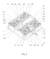
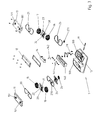
- FIG. 2 to 4 An example of a movement according to the invention is illustrated on the Figures 2 to 4 .
- the movement is built around a frame 1 provided with a plate 10 and a bottom 11, 12, 13 having two oblique faces 100, inclined, in this example of about 13 ° relative to the plate.
- the central portion 12 between the two inclined faces 11 and 13 is parallel to the plate 100 and the dial 94.
- This convex shape of the bottom makes it possible to reduce the support surface between the bottom of the watch and the wrist, and reduce perspiration problems.
- the bottom of the movement directly constitutes the bottom of the watch; the flat central portion 12 of the bottom of the movement is therefore directly in contact with the wrist of the wearer.
- the bottom 11, 12, 13 of the movement is preferably sealed with unreferenced seals to prevent moisture infiltration into the movement.
- each mirror is held by a frame (not referenced) screwed individually on the frame 1.
- the movement comprises four barrels 15, 16, 17 and 18 parallel to the two inclined faces 100 and provided with springs for storing the energy necessary to actuate the movement.
- the axes of the barrels are not perpendicular to the plate. Both ends of each axis are held by ball bearings, the upper bearings 151, 161, 171 and 181 being visible on the bearings. figures 2 and 3 .
- the springs of barrels are reloaded by the displacement of an oscillating mass, in this example a linear oscillating mass 14 moving under the effect of the movements of the carrier in a slide 140 under the central ice 120.
- the lower face of the oscillating mass 14 is provided with a rack 146 ( Figures 6 and 7 ) actuating a pinion 28 with a horizontal axis driving the left pulley 29 through the gear 26 or a gear train.
- the four barrels are each provided with two toothed pulleys, only the pulleys 150, 160, 170 and 180 near the bottom being visible on the figure 2 .
- the two barrels 15 and 16 are connected in series by means of a left winding belt 20 meshing with the first pulleys 150, 160 and a left discharge belt 24 ( figure 3 ) meshing with the second non-referenced pulleys.
- An upper left bridge 22 separates the two belts 20 and 24 in the path between the two barrels 15, 16.
- the belts 20 and 24 are tensioned by means of a tensioner 31 provided with an eccentric portion 310 and acting on the dorsal side of the belts; by adjusting the angular position of the eccentric portion 310 by means of the unreferenced screw, the length of the belt path is changed in order to adjust its tension.
- the belt 20 also meshes with the load pulley of the left barrels 29. The displacements of the oscillating mass 14 are therefore transmitted to the belt 20 via the gears 28 and 26 and the load pulley 29 to recharge the two barrels 15 and 16.
- the two barrels 17 and 18 are connected in series by means of a right winding belt 21 meshing with the first pulleys 170, 180 and a right discharge belt 25 meshing with the second non-referenced pulleys, a right upper deck 23 separating the two belts.
- the tension of the belts 21, 25 can be adjusted by the bottom by acting on the eccentric portion 320 of the tensioner 32.
- a load pulley of the straight barrels 30 is driven by the belt 21.
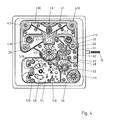
- the pulley 29 in the path of the belt 20 drives the pulley 30 on the path of the belt 21 by means of the toothed belt 41, visible on the figure 4 illustrating a view from above, through the plate 10 of the movement.
- the pulley 41 is stretched by the two tensioners 410 and 411 provided with eccentric portions. The oscillations of the mass 14 are thus also transmitted to the second pair of barrels 17, 18.
- the belt 24 connecting the second pulleys of the first pair of barrels 15, 16 drives a discharge pulley 270 actuating a left-handed distributor belt 42 of which only a portion is visible on the figure 4 .
- the belt 42 drives the upper plate of the torque splitter 40 whose role will be described below.
- the belt 25 connecting the second pulleys of the second pair of barrels 17, 18 drives a second pulley of discharge 271 actuating a right tundish belt 43, which drives the lower plate of the torque tappet 40.
- the torque distributor 40 comprises two plates supported against each other by a plate holding spring, not shown. One plate is driven by the left belt 42 while the other plate is driven by the right belt 43.
- the two plates are provided with teeth cooperating with each other, so that the couples transmitted by the two pairs of barrels 15-16 and 17 -18 add up.
- the toothing of the two plates is however arranged so that a difference in torque between the two plates tends to spread them against the force of the spring.
- the spacing between the two plates of the distributor is such that the two gears "unhook" and jump one step; the difference in torque is absorbed by the holding spring trays.
- the torque distributor 40 thus ensures that the two pairs of barrels 15-16 and 17-18 provide an approximately constant torque, even if the barrel springs do not have identical characteristics.
- a belt 44 connects the torque splitter 40 to the hour pulley (not shown) on the needle barrel 45 at the center of the movement.
- the hour pulley directly actuates the hour hand 92, as well as the minute pulley 60 through the minute belt 61.
- the minute pulley 60 drives the minute hand 91 through a gear or gear. an additional belt not shown.
- the rotations of the timing pulley 60 are further transmitted through a gear train and / or belts not shown to the small second pulley 48 which drives a small second belt 47 stretched by a return 49 49 to 16:30 .
- An additional pulley, or gear driven by the belt 47, drives the small second barrel 50 to drive the small second hand 93.
- a removable regulating member 51 mounted on a bridge 511 is fixed by screws 511 to the plate 10.
- the regulating member can be completely adjusted out of motion and then mounted after adjustment, only a second level fine adjustment by means of a single screw of the raqueterie being still necessary to adapt the march of the watch with each movement.
- the regulating member comprises several elements and is on the same plane as other members (40, for example) connected to the frame.
- the adjustment is thus greatly facilitated since the set of adjustment points is easily accessible when the regulating member is disassembled.
- the regulating member may be conventional, carousel, tourbillon or even electronic and comprises in this example an escapement 52, a portion of which is visible on the figure 4 . It is connected by a not shown gear train, or by an additional belt, to the small coaxial second wheel at the small second gun 52.
- belts may also be used to carry an index finger, a needle or any type of indicator on the dial, on the side edge or on an oblique surface of the watch, the horns or the bracelet.
- the use of belts, pulleys and universal joints also makes it possible to greatly facilitate the design of movements comprising several non-parallel bridges.
- the pulleys 29 and 30 are parallel to the barrels and inclined faces 100; their axes preferably comprise a cardan, or double cardan not shown, and for mounting pulleys or gears parallel to the plate 10.
- the axes of these two pulleys are connected to platinum through a cardan.
- the belt consists of a thin metal substrate 200, which gives it the required strength and transverse rigidity, on which is molded a greater thickness of rubber or synthetic material and in which the teeth 203 are formed.
- the interstices 202 between two teeth 203 are preferably rounded, for example semicircular, parabolic or cycloidal, while the teeth 202 of the belt are summed up with a thin ridge between two interstices. So, even when the belt 20 is very closed, the gap 202 between two teeth 203 remains wide enough that the teeth of the pulley can be introduced.
- the shape and size of the teeth of different pulleys collaborating with the same belt can also be adapted to the radius of curvature of the belt around the pulley.
- the Figures 6 and 7 illustrate by way of example the oscillating mass 14 used in the movement to reload the barrels through the kinematic chain 26-28.
- the oscillating mass moves linearly in a slide 140. Pivoting oscillating masses can, however, also be used with pulley movements according to the invention; moreover, the oscillating mass described can also be used with more conventional gear movements.
- the oscillating mass 14, which is visible by the bottom of the movement through the ice 120, is provided with four wheels 143 which allow it to slide between the lower rails 144 and upper 145 along the slide 140.
- the mass 14 is moves under the action of gravity and accelerations according to the movements of the wearer's wrist.
- Springs 141 and 142 are arranged at each end of the path of the mass in order to absorb shocks at the end of travel, to reduce the noise and to return the mass 14 in sense reverse. Spiral or elastomeric springs may also be used.
- a rack 146 on the basis of the oscillating mass 14 transmits the bidirectional linear movements of the mass 14 to the horizontal axis pinion 28, which converts them into circular motions transmitted through a kinematic chain to recharge the four barrels 15, 16, 17, 18.
- the slide 147 is simply fixed by means of screws 147 to the frame 1.
- the watch described has four barrels not parallel to each other and a torque splitter between these barrels, the man of the trade will understand that pulleys and belts may also be used with watches having a single barrel, or any number of barrels.
- belts in a watch movement is also appropriate when a mobile or indicator has to travel a very long trajectory or particular shape.
- the mobile or the indicator can be carried directly by the belt.
- a date-carrying belt for a large-date display, or to display moon phases, planetary displacements or tidal cycles along a route. two-dimensional or even three-dimensional trajectory.
Landscapes
- Physics & Mathematics (AREA)
- General Physics & Mathematics (AREA)
- Transmission Devices (AREA)
- Electric Clocks (AREA)
- Devices For Conveying Motion By Means Of Endless Flexible Members (AREA)
- Measurement Of Unknown Time Intervals (AREA)
- Electromechanical Clocks (AREA)
- Pulleys (AREA)
- Thermotherapy And Cooling Therapy Devices (AREA)
Abstract
Description
- La présente invention concerne un mouvement horloger pour montre bracelet, en particulier un dispositif d'entraînement pour mouvement de montre.
- La montre bracelet à mouvement mécanique est devenue un objet de luxe et par conséquent sujette à de nombreuses modifications du fait de l'effet de mode. Le boîtier a été l'élément de départ avec ses formes personnalisées, puis le bracelet avec ses formes et matières différentes et ses dispositifs de fermeture. Est venu ensuite l'intérieur de la montre et son mécanisme. De plus en plus ce mouvement a fait l'objet de complications mécaniques montrant ainsi l'ingéniosité des différents systèmes et le savoir-faire du maître d'oeuvre. Il est bien évident que c'est là que les possibilités sont les plus nombreuses et rien ne peut arrêter l'imagination du créateur.
- Les montres mécaniques usuelles comportent un accumulateur d'énergie constitué par un barillet, un organe de comptage, ou rouage, un organe de régulation, ou distribution, comportant un échappement et un balancier-spiral qui déterminent la marche de la montre, ainsi qu'un affichage assuré en général par des aiguilles sur un cadran. La présente invention concerne plus particulièrement la chaîne cinématique de transmission de l'énergie et des mouvements entre ces différents organes. Dans les mouvements mécaniques conventionnels, ainsi que dans les mouvements à quartz, les couples et les mouvements sont transmis entre les différents éléments mobiles d'une montre au moyen d'engrenages. Ainsi, le ressort de barillet, en se désarmant, entraîne le tambour de barillet en rotation, puis d'engrenage en engrenage jusqu'au pignon d'échappement et jusqu'aux aiguilles. Les engrenages sont constitués par des roues dentées ou par des crémaillères engrenées directement les uns aux autres.
- Les engrenages sont un moyen de transmission d'énergie efficace et dont la fiabilité est éprouvée. Au cours de la réflexion ayant mené à l'invention, il a toutefois été constaté qu'ils imposent un certain nombre de contraintes aux constructeurs de mouvements. Ainsi, les axes des deux roues d'un engrenage doivent être parallèles ou éventuellement perpendiculaires; des axes d'orientation quelconques sont uniquement possibles avec des engrenages coniques coûteux, difficiles à fabriquer et de plus faible rendement. Pour cette raison, les mouvements de montre sont presque toujours construits autour d'une platine et de ponts parallèles entre eux. Ainsi, les mouvements de montre comportent presque toujours deux faces principales planes et parallèles entre elles, toute autre géométrie imposant des contraintes difficiles à surmonter pour la réalisation du train d'engrenage.
- Dans le cas de montres de grand diamètre, un mouvement plat n'est pas toujours optimal; une forme incurvée, par exemple une forme concave adaptée au poignet ou une forme convexe permettant à la peau de respirer est souvent désirable. Il serait aussi souhaitable de pouvoir afficher des aiguilles ou d'autres indicateurs non parallèles au cadran, par exemple sur les faces latérales de la montre ou dans un plan oblique. Ces réalisations sont toutefois difficiles à réaliser avec des engrenages cylindriques dont les axes sont parallèles.
- Les engrenages transmettent l'énergie de manière efficace uniquement lorsque les deux roues engrenées sont parfaitement alignées et espacées correctement. Dans une montre, il est donc nécessaire de fixer les axes de roues et des pignons avec une très grande précision, ce qui renchérit le coût de fabrication. Des déplacements minimes provoqués par un choc ou une accélération peuvent bloquer l'engrenage; il est donc nécessaire d'utiliser des axes rigides et fixés à la platine et aux ponts à l'aide de moyens antichocs, par exemple de pierres et de paliers incablocs™. Ces éléments sont coûteux, fragiles et difficiles à assembler. Par ailleurs, les dents des composants de l'engrenage doivent impérativement être fabriquées en métal dur afin de limiter leur usure et de garantir un contact optimal même après plusieurs années de fonctionnement.
- Les engrenages ont par ailleurs l'inconvénient de nécessiter une lubrification qui doit être répétée périodiquement.
- Les engrenages sont aussi peu appropriés à l'entraînement de roues ou de mobiles éloignés les uns des autres dans un mouvement, dans un tel cas, une chaîne d'engrenages intermédiaire doit être utilisée, qui renchérit le coût du mouvement, réduit sa fiabilité et nécessite des axes supplémentaires. Une autre solution chère et encombrante est d'augmenter le diamètre des deux roues de l'engrenage.
- Enfin, les deux roues d'un engrenage tournent nécessairement en sens opposé; lorsqu'il est nécessaire de les faire tourner dans le même sens, une roue ou un pignon intermédiaire doit être utilisé qui renchérit le mouvemement et nécessite une place supplémentaire dans l'espace réduit du mouvement. Par exemple, la roue des minutes ne peut pas engrener directement avec la roue des heures ni avec celles des secondes, puisque les trois aiguilles correspondantes doivent tourner dans le même sens.
- Un but de la présente invention est donc de proposer un mouvement de montre qui évite ces inconvénients.
- Un autre but est d'utiliser de moyens alternatifs dans la chaîne cinématique d'un mouvement de montre, provoquant un effet de surprise par le choix d'une technologie inhabituelle.
- Un autre but est de proposer un mouvement de montre de conception alternative et nouvelle qui autorise des constructions et de designs différents des mouvements conventionnels.
- Selon l'invention, ces buts sont atteints au moyen d'un mouvement de montre qui présente les caractéristiques de la revendication 1, des modes de réalisation préférentiels étant par ailleurs indiqués dans la description
- En particulier, ces buts sont atteints grâce à un mouvement horloger destiné à être intégré dans un boîte de montre-bracelet et comportant au moins une courroie pour transmettre les mouvements et/ou les couples entre au moins deux poulies (c'est-à-dire entre une poulie entraînante et au moins une poulie entraînée).
- En remplaçant un ou plusieurs engrenages par un ensemble formé de deux poulies et d'une courroie, on obtient tout d'abord un effet de surprise, particulièrement si les courroies sont visibles au travers du fond de la montre ou au travers du cadran. Par ailleurs, les différentes poulies connectées par une même courroie peuvent être orientées dans des plans différents, ce qui donne une liberté supplémentaire au constructeur de mouvement lors de la conception d'un nouveau mouvement.
- Les autres problèmes des engrenages évoqués plus haut sont aussi résolus.
- Le terme de courroie doit être interprété de manière large dans ladite demande pour inclure des courroies lisses ou crantées, des chaînes, des bandes et des câbles de transmission entre poulies. Toutefois, dans une variante préférentielle, la courroie utilisée est une courroie au moins partiellement en matériau synthétique et munie de crans (dents).
- Le document
CH61963 - Des pendules murales ou de table munies de chaînes et de courroies sont aussi décrites dans
US1667685 ,US2494011 ,US4320480 ,US5105398 ,US4022015 et dansUS4676662 . Tous ces documents concernent cependant des horloges et pendules de grandes dimensions, dont le mouvement ne peut en aucun cas être miniaturisé pour être logé dans une montre bracelet. -
FR391702 - L'invention sera mieux comprise à la lecture d'un exemple annexé illustré par les figures qui montrent:
- La
figure 1 une vue de dessus d'une montre bracelet incluant un mouvement horloger selon l'invention. - La
figure 2 une vue en perspective de trois quarts d'un mouvement horloger selon l'invention. - La
figure 3 un éclaté partiel du mouvement horloger de l'invention. - La
figure 4 une vue de dessus du mouvement de l'invention, vu à travers la platine. - La
figure 5 un détail d'une courroie. - La
figure 6 une coupe longitudinale de la masse oscillante linéaire du mouvement horloger de l'invention. - La
figure 7 une coupe transversale de la masse oscillante linéaire du mouvement horloger de l'invention. - Une montre 9 équipée d'un mouvement horloger selon l'invention est illustrée à titre d'exemple sur la
figure 1 . La montre comporte une boîte 90 permettant d'emboîter le mouvement par le fond, comme on le verra. Une couronne de remontoir et de mise à l'heure 19, liée à un module de remontage et de mise à l'heure amovible 62 (figure 4 ) permet de remonter et/ou de mettre la montre à l'heure. Des aiguilles de minute 91 et d'heure 92, ainsi qu'une aiguille de petite seconde 93 à 16h30 se déplacent au-dessus d'un cadran 94 afin d'afficher l'heure. Le cadran comporte au moins une ouverture 95 permettant d'apercevoir au moins une partie du mouvement, de préférence une partie du mouvement comportant une courroie ou un tronçon significatif de courroie, comme on le verra plus loin. - Dans une autre variante non illustrée, la montre est de type squelette, c'est-à-dire dépourvue de cadran, et les aiguilles se déplacent directement au-dessus du mouvement. Dans encore une autre variante non illustrée, le cadran est constitué d'un verre ou d'un matériau synthétique opaque pour un observateur qui le regarde en face, et transparent lorsqu'on l'incline par rapport à la direction du regard. Cette variante, qui peut du reste être utilisée en combinaison avec n'importe quel mouvement de montre, permet de distinguer facilement les aiguilles au-dessus du cadran lorsque celui-ci est incliné en position de lecture, et de vérifier le fonctionnement du mouvement simplement en orientant la montre dans une direction préférentielle. Dans une autre variante, le cadran pourrait être constitué d'une cellule de cristaux liquides opaque au repos et transparents lorsqu'une tension entre les deux faces oriente les cristaux différemment.
- Un exemple de mouvement selon l'invention est illustré sur les
figures 2 à 4 . Le mouvement est construit autour d'un châssis 1 muni d'une platine 10 et d'un fond 11, 12, 13 comportant deux faces obliques 100, inclinées, dans cet exemple d'environ 13° par rapport à la platine. La portion centrale 12 entre les deux faces inclinées 11 et 13 est parallèle à la platine 100 et au cadran 94. Cette forme convexe du fond permet de réduire la surface d'appui entre le fond de la montre et le poignet, et de réduire les problèmes de transpiration. - Selon une caractéristique indépendante de l'invention, le fond du mouvement constitue directement le fond de la montre; la portion centrale plane 12 du fond du mouvement est donc directement en contact avec le poignet du porteur. Le fond 11, 12, 13 du mouvement est de préférence étanchéifié à l'aide de joints non référencés afin d'empêcher les infiltrations d'humidité dans le mouvement.
- Afin de contrôler le fonctionnement du mouvement, les faces 11, 12, 13 sont fermées par des glaces 110, 120, 130 respectivement. Dans l'exemple, chaque glace est tenue par un cadre (non référencé) vissé individuellement sur le châssis 1.
- Le mouvement comporte quatre barillets 15, 16, 17 et 18 parallèles aux deux faces inclinées 100 et munis de ressorts pour emmagasiner l'énergie nécessaire à actionner le mouvement. Les axes des barillets ne sont donc pas perpendiculaires à la platine. Les deux extrémités de chaque axe sont tenues par des roulements à bille, les roulements supérieurs 151, 161, 171 et 181 étant visibles sur les
figures 2 et3 . Les ressorts de barillets sont rechargés par le déplacement d'une masse oscillante, dans cet exemple une masse oscillante linéaire 14 se déplaçant sous l'effet des mouvements du porteur dans une coulisse 140 sous la glace centrale 120. La face inférieure de la masse oscillante 14 est munie d'une crémaillère 146 (figures 6 et 7 ) actionnant un pignon 28 à axe horizontal entraînant la poulie de renvoi gauche 29 au travers de l'engrenage 26 ou d'un train d'engrenage. - Les quatre barillets sont munis chacun de deux poulies crantées, seules les poulies 150, 160, 170 et 180 proches du fond étant visibles sur la
figure 2 . Les deux barillets 15 et 16 sont reliés en série au moyen d'une courroie de remontage gauche 20 engrenant avec les premières poulies 150, 160 et d'une courroie de décharge gauche 24 (figure 3 ) engrenant avec les deuxièmes poulies non référencées. Un pont supérieur gauche 22 sépare les deux courroies 20 et 24 dans le chemin entre les deux barillets 15, 16. Les courroies 20 et 24 sont tendues au moyen d'un tendeur 31 muni d'une portion excentrique 310 et agissant sur la face dorsale des courroies; en réglant la position angulaire de la portion excentrique 310 au moyen de la vis non référencée, on modifie la longueur du chemin de courroie afin de régler sa tension. La courroie 20 engrène en outre avec la poulie de charge des barillets gauches 29. Les déplacements de la masse oscillante 14 sont donc transmis à la courroie 20 par l'intermédiaire des engrenages 28 et 26 et de la poulie de charge 29 pour recharger les deux barillets 15 et 16. - De la même façon, les deux barillets 17 et 18 sont reliés en série au moyen d'une courroie de remontage droite 21 engrenant avec les premières poulies 170, 180 et d'une courroie de décharge droite 25 engrenant avec les deuxièmes poulies non référencées, un pont supérieur droit 23 séparant les deux courroies. La tension des courroies 21, 25 peut être réglée par le fond en agissant sur la portion excentrique 320 du tendeur 32. Une poulie de charge des barillets droits 30 est entraînée par la courroie 21.
- La poulie 29 sur le chemin de la courroie 20 entraîne la poulie 30 sur le chemin de la courroie 21 au moyen de la courroie crantée 41, visible sur la
figure 4 illustrant une vue de dessus, au travers de la platine 10 du mouvement. La poulie 41 est tendue par les deux tendeurs 410 et 411 munis de portions excentriques. Les oscillations de la masse 14 sont ainsi également transmises à la deuxième paire de barillets 17, 18. - La courroie 24 reliant les deuxièmes poulies de la première paire de barillets 15, 16 entraîne une poulie de décharge 270 actionnant une courroie de répartiteur gauche 42 dont seule une portion est visible sur la
figure 4 . La courroie 42 entraîne le plateau supérieur du répartiteur de couple 40 dont le rôle sera décrit plus bas. - De la même façon, la courroie 25 reliant les deuxièmes poulies de la deuxième paire de barillets 17, 18 entraîne une deuxième poulie de décharge 271 actionnant une courroie de répartiteur droite 43, qui entraîne le plateau inférieur du répartiteur de couple 40.
- Le répartiteur de couple 40 comporte deux plateaux appuyés l'un contre l'autre par un ressort de maintien des plateaux, non représenté. Un plateau est entraîné par la courroie gauche 42 tandis que l'autre plateau est entraîné par la courroie droite 43. Les deux plateaux sont munis de dentures coopérant mutuellement, en sorte que les couples transmis par les deux paires de barillets 15-16 et 17-18 s'additionnent. La denture des deux plateaux est toutefois agencée de manière à ce qu'une différence de couple entre les deux plateaux tende à les écarter à l'encontre de la force du ressort. Lorsque cette différence de couple devient importante, l'écartement entre les deux plateaux du répartiteur est telle que les deux engrenages "décrochent" et sautent un pas; la différence de couple est donc absorbée par le ressort de maintien des plateaux. Le répartiteur de couple 40 permet ainsi de garantir que les deux paires de barillets 15-16 et 17-18 fournissent un couple approximativement constant, même si les ressorts de barillets n'ont pas des caractéristiques identiques.
- Une courroie 44 relie le répartiteur de couple 40 à la poulie des heures (non représentée) sur le canon des aiguilles 45 au centre du mouvement. La poulie des heures actionne directement l'aiguille des heures 92, ainsi que la poulie de minuterie 60 au travers de la courroie de minutes 61. La poulie de minuterie 60 entraîne l'aiguille des minutes 91 au travers d'un engrenage ou d'une courroie supplémentaire non représentée.
- Les rotations de la poulie de minuterie 60 sont en outre transmises au travers d'un train d'engrenages et/ou de courroies non représenté à la poulie de petite seconde 48 qui entraîne une courroie de petite seconde 47 tendue par un renvoi 49 à 16h30. Une poulie supplémentaire, ou un engrenage actionné par la courroie 47, permet d'entraîner le canon de petite seconde 50 pour entraîner l'aiguille de petite seconde 93.
- Un organe réglant 51 amovible monté sur un pont 511 est fixé par des vis 511 à la platine 10. L'organe réglant peut être entièrement réglé hors du mouvement puis monté après réglage, seul un réglage fin de deuxième niveau au moyen d'une seule vis de la raqueterie étant encore nécessaire pour adapter la marche de la montre à chaque mouvement. L'organe réglant comporte plusieurs éléments et se trouve sur le même plan que d'autres organes (40, par exemple) liés au châssis.
- Le réglage est ainsi grandement facilité puisque l'ensemble des points de réglage est accessible aisément lorsque l'organe réglant est démonté. L'organe réglant peut être conventionnel, à carrousel, à tourbillon ou même électronique et comporte dans cet exemple un échappement 52 dont une portion est visible sur la
figure 4 . Il est relié par un train d'engrenages non représenté, ou par une courroie supplémentaire, à la roue de petite seconde coaxiale au canon de petite seconde 52. - Ainsi la quasi-totalité du train d'engrenage des mouvements de montre traditionnels est remplacé par des courroies et des poulies. En particulier, la chaîne cinématique entre les barillets et le canon des aiguilles est entièrement constituée de courroies. Par ailleurs, les paliers et rubis habituels sont au moins partiellement remplacés par des roulements à bille maintenant les axes de poulies. Les tolérances sur le positionnement des axes lors du montage du mouvement peuvent ainsi être relâchées, puisque les courroies peuvent absorber des erreurs de parallélisme ou d'écartement entre poulies même relativement importantes. Par ailleurs, il est possible de disposer des poulies dans des plans non parallèles entre eux, ce qui donne au constructeur de mouvement une liberté supplémentaire lors de la conception. Par exemple, des courroies peuvent aussi être utilisées pour transporter un index, une aiguille ou n'importe quel type d'indicateur sur le cadran, sur le bord latéral ou sur une surface oblique de la montre, des cornes ou du bracelet. L'utilisation de courroies, de poulies et de cardans permet en outre de faciliter grandement la conception de mouvements comportant plusieurs ponts non parallèles entre eux.
- Les poulies 29 et 30 sont parallèles aux barillets et aux faces inclinées 100; leurs axes comportent de préférence un cardan, ou un double cardan non représenté, et permettant de monter des poulies ou des engrenages parallèles à la platine 10. Les axes de ces deux poulies sont donc liés à platine au travers d'un cardan.
- La
figure 5 illustre à titre d'exemple un tronçon de courroie 20 selon l'invention. Différentes contraintes sont posées aux courroies du mouvement: - ■ Longueurs et sections nettement inférieures à celles des courroies connues dans d'autres domaines de la technique.
- ■ Fonctionnement en continu ou quasi-continu avec un minimum d'usure et d'élongation.
- ■ Doit pouvoir collaborer avec des poulies et des renvois de diamètres fortement variables.
- ■ Suffisamment élastiques pour pouvoir être tendues au moyen des tendeurs et, si désiré, pour pouvoir être vrillée entre deux poulies non parallèles.
- ■ Suffisamment rigides pour ne pas quitter la poulie, même en cas de chocs importants.
- Selon l'invention, la courroie est constituée d'un substrat métallique fin 200, qui lui donne la solidité et la rigidité transversale requises, sur lequel est surmoulée une épaisseur de caoutchouc ou de matériau synthétique plus importante et dans laquelle sont formées les dents 203. Afin de garantir un angle de contact avec les dents de la courroie acceptable quel que soit le rayon de courbure de la courroie, les interstices 202 entre deux dents 203 sont de préférence arrondis, par exemple demi-circulaires, paraboliques ou cycloïdes, tandis que les dents 202 de la courroie se résument à une arête fine entre deux interstices. Ainsi, même lorsque la courroie 20 est très refermée, l'interstice 202 entre deux dents 203 reste suffisamment large pour que les dents de la poulie puissent y être introduites. La forme et la taille des dents de différentes poulies collaborant avec une même courroie peuvent aussi être adaptées au rayon de courbure de la courroie autour de la poulie.
- Des courroies lisses ou pourvues de dents de formes différentes peuvent aussi être utilisées dans le cadre de l'invention.
- Les
figures 6 et 7 illustrent à titre d'exemple la masse oscillante 14 utilisée dans le mouvement pour recharger les barillets au travers de la chaîne cinématique 26-28. Selon l'invention, la masse oscillante se déplace linéairement dans une coulisse 140. Des masses oscillantes pivotantes peuvent cependant aussi être utilisées avec des mouvements à poulies selon l'invention; par ailleurs, la masse oscillante décrite peut aussi être utilisée avec des mouvements plus conventionnels à engrenages. La masse oscillante 14, qui est visible par le fond du mouvement au travers de la glace 120, est munie de quatre roues 143 qui lui permettent de coulisser entre des rails inférieurs 144 et supérieurs 145 le long de la coulisse 140. La masse 14 se déplace sous l'action de la gravité et des accélérations en fonction des mouvements du poignet du porteur. - Des ressorts 141 et 142, constitués dans cet exemple par des lames métalliques flexibles recourbées, sont disposées à chaque extrémité du parcours de la masse afin d'absorber les chocs en bout de course, de réduire le bruit et de renvoyer la masse 14 en sens inverse. Des ressorts spiraux ou élastomères peuvent aussi être utilisés. Une crémaillère 146 sur la base de la masse oscillante 14 transmet les mouvements linéaires bidirectionnels de la masse 14 au pignon à axe horizontal 28, qui les convertit en mouvements circulaires transmis au travers d'une chaîne cinématique pour recharger les quatre barillets 15, 16, 17, 18. La coulisse 147 est simplement fixée au moyen de vis 147 au châssis 1.
- Bien que la montre décrite comporte quatre barillets non parallèles entre eux et un répartiteur de couple entre ces barillets, l'homme du métier comprendra que des poulies et des courroies peuvent aussi être utilisées avec des montres comportant un seul barillet, ou n'importe quel nombre de barillets.
- L'utilisation de courroies dans un mouvement de montre est aussi appropriée lorsqu'un mobile ou un indicateur doit parcourir une trajectoire très longue ou de forme particulière. Dans ce cas, le mobile ou l'indicateur peut être porté directement par la courroie. Par exemple, il serait possible dans le cadre de l'invention d'utiliser une courroie portant des quantièmes pour un afficheur de grande date, ou pour afficher des phases de lune, des déplacements de planètes ou des cycles de marées le long d'une trajectoire bidimensionnelle ou même tridimensionnelle.
Claims (13)
- Mouvement horloger destiné à être intégré dans une boîte de montre-bracelet (9) et comprenant une chaine cinématique pour modifier la position angulaire d'au moins une aiguille (91, 92, 93),
caractérisé en ce que ladite chaîne cinématique comprend au moins une courroie (20, 21, 24, 25, 42, 43, 44, 45, 47) pour transmettre les mouvements et/ou les couples entre au moins deux poulies (150, 160, 170, 180, 29, 30, 270,271). - Mouvement horloger selon la revendication 1, caractérisé en ce qu'il est de type mécanique et comporte au moins un barillet (15, 16, 17, 18), au moins une courroie étant prévue dans la chaîne cinématique entre lesdits barillets et lesdites aiguilles.
- Mouvement horloger selon la revendication 2, dans lequel au moins une dite courroie (42, 43, 44) est utilisée pour transmettre l'énergie emmagasinée par ledit ou lesdits barillets (15, 16, 17, 18) au reste de la montre.
- Mouvement horloger selon l'une des revendications 1 à 3, dans lequel au moins une dite courroie (20, 21) est au moins partiellement visible sur la face inférieure du mouvement.
- Mouvement horloger selon l'une des revendications 1 à 4, dans lequel au moins une dite courroie (47) est au moins partiellement visible au travers d'un guichet (95) dans le cadran (94) de la montre.
- Mouvement horloger selon l'une des revendications 1 à 5, comprenant au moins une poulie (29, 30) non parallèle à la platine (10) du mouvement.
- Mouvement horloger selon l'une des revendications 1 à 6, au moins une desdites courroies (20, 21) étant crantée.
- Mouvement horloger selon l'une des revendications 1 à 7, au moins une des dites courroies (20) étant fabriquée par surmoulage de matériau synthétique (201) sur un substrat métallique (200).
- Mouvement horloger selon l'une des revendications 1 à 8, lesdits barillets (15, 16, 17, 18) étant tendus par les déplacements d'une masse oscillante linéaire (14) visible au travers du fond du mouvement.
- Mouvement horloger selon la revendication 1, comportant une poulie des heures actionnant directement l'aiguille des heures (92).
- Mouvement horloger selon la revendication 1, comportant une poulie de minuterie (60) actionnée au travers d'une courroie de minutes (61).
- Mouvement horloger selon la revendication 1, comportant une aiguille de petite seconde (93) actionnée par une courroie de petite seconde (47).
- Montre bracelet (9) comprenant un mouvement selon l'une des revendications 1 à 12.
Applications Claiming Priority (3)
| Application Number | Priority Date | Filing Date | Title |
|---|---|---|---|
| CH01188/02A CH705048B1 (fr) | 2002-07-09 | 2002-07-09 | Dispositif d'entraînement par courroies lisses ou crantées d'un mouvement de montre mécanique. |
| PCT/EP2003/050301 WO2004006026A2 (fr) | 2002-07-09 | 2003-07-09 | Mouvement horloger pour montre bracelet |
| EP03762695A EP1520214B1 (fr) | 2002-07-09 | 2003-07-09 | Mouvement horloger pour montre bracelet |
Related Parent Applications (2)
| Application Number | Title | Priority Date | Filing Date |
|---|---|---|---|
| EP03762695.9 Division | 2003-07-09 | ||
| EP03762695A Division EP1520214B1 (fr) | 2002-07-09 | 2003-07-09 | Mouvement horloger pour montre bracelet |
Publications (3)
| Publication Number | Publication Date |
|---|---|
| EP2259157A2 true EP2259157A2 (fr) | 2010-12-08 |
| EP2259157A3 EP2259157A3 (fr) | 2011-01-26 |
| EP2259157B1 EP2259157B1 (fr) | 2018-10-31 |
Family
ID=30005584
Family Applications (2)
| Application Number | Title | Priority Date | Filing Date |
|---|---|---|---|
| EP03762695A Expired - Lifetime EP1520214B1 (fr) | 2002-07-09 | 2003-07-09 | Mouvement horloger pour montre bracelet |
| EP10180522.4A Expired - Lifetime EP2259157B1 (fr) | 2002-07-09 | 2003-07-09 | Mouvement horloger pour montre bracelet |
Family Applications Before (1)
| Application Number | Title | Priority Date | Filing Date |
|---|---|---|---|
| EP03762695A Expired - Lifetime EP1520214B1 (fr) | 2002-07-09 | 2003-07-09 | Mouvement horloger pour montre bracelet |
Country Status (13)
| Country | Link |
|---|---|
| US (3) | US7697376B2 (fr) |
| EP (2) | EP1520214B1 (fr) |
| JP (2) | JP4666689B2 (fr) |
| KR (1) | KR100854940B1 (fr) |
| CN (1) | CN1672102B (fr) |
| AT (1) | ATE488787T1 (fr) |
| AU (1) | AU2003254502A1 (fr) |
| CH (3) | CH705048B1 (fr) |
| DE (1) | DE60334992D1 (fr) |
| RU (1) | RU2310898C2 (fr) |
| TW (1) | TWI259938B (fr) |
| WO (1) | WO2004006026A2 (fr) |
| ZA (1) | ZA200500125B (fr) |
Families Citing this family (35)
| Publication number | Priority date | Publication date | Assignee | Title |
|---|---|---|---|---|
| WO2002077723A1 (fr) * | 2001-03-21 | 2002-10-03 | Glashütter Uhrenbetrieb GmbH | Piece d'horlogerie comportant un mecanisme pour l'enclenchement d'une fonction horaire et l'armage simultane d'un ressort de barillet |
| CH705048B1 (fr) | 2002-07-09 | 2012-12-14 | Lvmh Swiss Mft Sa | Dispositif d'entraînement par courroies lisses ou crantées d'un mouvement de montre mécanique. |
| DE602004016282D1 (de) * | 2004-04-01 | 2008-10-16 | Richemont Int Sa | Uhrwerk mit mehreren Federhäusern |
| EP1753581A1 (fr) | 2004-06-08 | 2007-02-21 | Tag-Heuer S.A. | Procede de fabrication d'une piece micro- ou nanomecanique par une etape d'ablation laser a l'aide d'un femtolaser |
| US7252113B2 (en) | 2004-07-14 | 2007-08-07 | L.R. Nelson Corporation | Mechanical in line timer valve |
| EP1840676A1 (fr) | 2006-03-29 | 2007-10-03 | Francis Gerber | Pièce d'horlogerie à affichage par ruban |
| EP1884841A1 (fr) * | 2006-08-01 | 2008-02-06 | Agenhor SA | Mouvement d'horlogerie permettant de commander un organe d'affichage suivant une trajectoire complexe et pièce d'horlogerie comportant un tel mouvement |
| US7568831B2 (en) * | 2006-10-06 | 2009-08-04 | Tiffany & Co. Watch Center Ag | Tourbillion-type timepiece movement |
| RU2446425C2 (ru) * | 2007-02-08 | 2012-03-27 | Комплитайм Са | Часовой механизм |
| IT1398711B1 (it) * | 2009-10-19 | 2013-03-18 | Bissolotti | Quadrante di orologio in cui le ore non hanno uguali angoli al centro. |
| US8355297B2 (en) | 2009-11-05 | 2013-01-15 | Devon Works, LLC | Watch assembly having a plurality of time-coordinated belts |
| CH702776A1 (fr) * | 2010-03-01 | 2011-09-15 | Interlemo Holding Sa | Module horloger comportant un organe moteur a plusieurs barillets et un dispositif d'armage. |
| USD631375S1 (en) | 2010-05-14 | 2011-01-25 | Devon Works, LLC | Watch |
| RU2598377C2 (ru) * | 2011-05-09 | 2016-09-27 | Те Свотч Груп Рисерч Энд Дивелопмент Лтд | Часы, содержащие покрытие, включающее полимерные щетки |
| FR2988866B1 (fr) * | 2012-04-02 | 2014-12-26 | Daniel Messerli | Montre analogique munie d’un mobile decoratif |
| RU2526561C1 (ru) * | 2012-12-21 | 2014-08-27 | Общество с ограниченной ответственностью "Часовой завод "НИКА" | Наручные таинственные часы |
| USD782337S1 (en) * | 2015-12-04 | 2017-03-28 | Nixon, Inc. | Watch |
| USD782338S1 (en) * | 2015-12-04 | 2017-03-28 | Nixon, Inc. | Watch |
| USD782336S1 (en) * | 2015-12-04 | 2017-03-28 | Nixon Inc. | Watch |
| CA176786S (en) * | 2017-03-17 | 2018-12-24 | Lvmh Swiss Mft Sa | Watch movement |
| USD847665S1 (en) * | 2017-03-17 | 2019-05-07 | Lvmh Swiss Manufactures Sa | Watch movement in a watch case |
| EP3382468B1 (fr) * | 2017-03-30 | 2020-01-15 | The Swatch Group Research and Development Ltd | Mouvement avec prolongateur de réserve de marche |
| EP3620865B1 (fr) | 2018-09-05 | 2021-02-24 | The Swatch Group Research and Development Ltd | Piece d'horlogerie mecanique ou electromecanique a entrainement mysterieux |
| CN109081040A (zh) * | 2018-09-07 | 2018-12-25 | 江苏三科精工机械有限公司 | 一种料槽转动摆臂 |
| USD953892S1 (en) * | 2019-07-15 | 2022-06-07 | Ksenia Kiseleva | Watch with a QR code |
| EP3828645B1 (fr) * | 2019-11-27 | 2025-11-12 | Montres Breguet S.A. | Montre squelette |
| USD917310S1 (en) * | 2020-01-31 | 2021-04-27 | Citizen Watch Co., Ltd. | Watch |
| CN111708272A (zh) * | 2020-07-01 | 2020-09-25 | 嘉兴麦远文化传媒有限公司 | 一种防止汗渍积淀的智能通讯手表 |
| IT202100004790A1 (it) * | 2021-03-02 | 2022-09-02 | Lonati Spa | Dispositivo di movimentazione. |
| EP4194963A1 (fr) * | 2021-12-10 | 2023-06-14 | Blancpain SA | Mouvement d'horlogerie comprenant un organe muni de moyens d'ajustement variable de l'inclinaison |
| USD989635S1 (en) * | 2022-03-31 | 2023-06-20 | CODE41 Sàrl | Table clock |
| JP7252406B1 (ja) * | 2022-10-14 | 2023-04-04 | ナカソネ住設株式会社 | スケルトン形コンソール時計 |
| USD1030515S1 (en) * | 2023-04-28 | 2024-06-11 | Lvmh Swiss Manufactures Sa | Watch case with dial |
| USD1059181S1 (en) * | 2023-05-25 | 2025-01-28 | Lvmh Swiss Manufactures Sa | Watch case with dial |
| CH721004A1 (fr) * | 2023-08-02 | 2025-02-14 | Hublot Sa Geneve | Dispositif de remontage automatique d'un ressort de barillet |
Citations (8)
| Publication number | Priority date | Publication date | Assignee | Title |
|---|---|---|---|---|
| FR391702A (fr) | 1908-06-25 | 1908-11-07 | Victor Forti | Système d'allumage automatique des becs de gaz |
| CH61963A (de) | 1912-03-25 | 1913-11-01 | Franz Kastner | Acht Tage gehende Pendeluhr mit Schlagwerk und gemeinsamer Aufziehvorrichtung für das Gang- und Schlagwerk |
| US1667685A (en) | 1923-11-10 | 1928-04-24 | Schwab & Sons Ag | Clock attachment |
| US2494011A (en) | 1945-12-10 | 1950-01-10 | Harold G Stein | Clock |
| US4022015A (en) | 1974-02-11 | 1977-05-10 | Bailey James R | Time indicating device |
| US4320480A (en) | 1980-05-01 | 1982-03-16 | Dieter Graesslin Feinwerktechnik | Switch chain with switch riders for switch clocks |
| US4676662A (en) | 1985-12-16 | 1987-06-30 | Chiaki Sekido | Large clock driven by solar cell |
| US5105398A (en) | 1987-09-25 | 1992-04-14 | Seikosha Co., Ltd. | Three hands type clock with belt drive |
Family Cites Families (92)
| Publication number | Priority date | Publication date | Assignee | Title |
|---|---|---|---|---|
| DE499642C (de) * | 1930-06-13 | Alexander Gaertner | Zeitanzeiger fuer die 24-Stunden-Zeit | |
| CH60360A (fr) | 1912-06-07 | 1913-07-16 | Movado L A J Ditesheim & Frere | Montre-bracelet |
| DE281385C (fr) | 1912-09-20 | |||
| CH104594A (fr) * | 1923-05-24 | 1924-05-01 | Co Jura Watch | Montre à mouvement visible. |
| GB218553A (en) * | 1923-11-17 | 1924-07-10 | Thomas Gregg Towne | Improvements in or relating to watches |
| US1572097A (en) * | 1925-03-12 | 1926-02-09 | Nils P Walters | Timepiece |
| GB281385A (en) * | 1926-09-01 | 1927-12-01 | Reginald Norman Reid | Calendar clock |
| US1676030A (en) * | 1926-09-17 | 1928-07-03 | Francis A Helin | Twenty-four-hour clock |
| US1914015A (en) | 1930-01-11 | 1933-06-13 | Hatot Leon | Self winding watch |
| US1893882A (en) * | 1930-04-24 | 1933-01-10 | Oscar Langlo | Toy clock |
| DE529785C (de) * | 1931-01-08 | 1931-07-16 | Uhrenfabrik La Champagne Louis | Uhr mit Ruettelaufzug |
| CH156804A (fr) * | 1931-06-09 | 1932-08-31 | Montres Wyler S A Fab Des | Montre à remontage automatique. |
| CH157997A (fr) * | 1931-09-29 | 1932-10-31 | Eterna Schild Freres & Co Fab | Pièce d'horlogerie à remontoir automatique. |
| CH164257A (fr) * | 1932-11-01 | 1933-09-30 | Schild Sa A | Montre-bracelet à remontage automatique. |
| CH172127A (fr) * | 1933-04-13 | 1934-09-30 | Leon Levy & Freres S A | Pièce d'horlogerie à remontage automatique. |
| US2024066A (en) * | 1935-04-16 | 1935-12-10 | Crispin B Segovia | Geographical clock |
| CH190207A (fr) * | 1936-06-24 | 1937-04-15 | Bulova Watch Co Inc | Montre-bracelet. |
| US2221413A (en) * | 1939-02-28 | 1940-11-12 | Jacob L Schanz | Straight-line clock |
| CH212243A (fr) * | 1939-07-20 | 1940-11-15 | Colomb Henri | Mouvement de montre. |
| US2431968A (en) * | 1945-11-24 | 1947-12-02 | James M Sparkes | Calendar timepiece |
| US2506134A (en) * | 1946-11-05 | 1950-05-02 | Burchell Holloway Corp | Clock display device |
| CH291567A (fr) * | 1951-06-29 | 1953-06-30 | Tavannes Watch Co Sa | Pièce d'horlogerie. |
| US2790300A (en) * | 1954-01-14 | 1957-04-30 | Lux Clock Mfg Company Inc | Calendar clock |
| US2952967A (en) * | 1957-02-04 | 1960-09-20 | Nussle Guillaume | Wrist-watch |
| CH337789A (fr) * | 1957-04-10 | 1959-04-15 | Nussle Guillaume | Montre |
| CH341449A (fr) * | 1958-09-11 | 1959-09-30 | Ebauches Sa | Compteur-avertisseur |
| GB1166256A (en) | 1965-10-14 | 1969-10-08 | Atkins Fulford Ltd | Improvements in or relating to Belt and Chain Gearing. |
| CH538715A (de) | 1967-04-15 | 1972-11-30 | Bueren Watch Company S A | Mouvement de montre à ressorts moteurs |
| DE2031341A1 (de) * | 1969-06-26 | 1971-01-07 | Citizen Watch Co Ltd , Tokio | Uhr mit Kalender |
| CH526804A (fr) * | 1969-10-27 | 1972-04-14 | Omega Brandt & Freres Sa Louis | Pièce d'horlogerie |
| ZA712713B (en) * | 1970-05-02 | 1972-01-26 | Dunlop Holdings Ltd | Improvements in toothed belts |
| JPS5149971Y2 (fr) * | 1971-02-17 | 1976-12-02 | ||
| DE2227335A1 (de) * | 1971-06-11 | 1973-02-15 | Cigala & Bertinetti S A S Di C | Treibriemen und verfahren zu seiner herstellung |
| DE2202041A1 (de) * | 1972-01-17 | 1973-07-26 | Baublys Mikas Dr Ing | Riemen mit mehreren metallschichten und verfahren zur herstellung desselben |
| US3759592A (en) * | 1972-03-24 | 1973-09-18 | Bearings Seals & Gears Inc | Memory disc drive spindle |
| JPS5322863B2 (fr) * | 1972-03-27 | 1978-07-11 | ||
| US3956879A (en) * | 1974-02-11 | 1976-05-18 | Bailey James R | Time indicating device |
| CH585926B5 (fr) * | 1974-06-10 | 1977-03-15 | Metallprodukte Ag Grenchen | |
| US3977176A (en) * | 1974-08-22 | 1976-08-31 | Citizen Watch Co., Ltd. | Electronic watch structure |
| CH599580B5 (fr) * | 1974-08-22 | 1978-05-31 | Longines Montres Comp D | |
| US3942316A (en) * | 1974-11-08 | 1976-03-09 | Bulova Watch Company, Inc. | Sectioned casing for electronic watches |
| US4033110A (en) * | 1975-12-22 | 1977-07-05 | Bulova Watch Company, Inc. | Solid-state electronic watch assembly |
| US4103484A (en) * | 1976-07-22 | 1978-08-01 | Bailey James R | Time indicating device |
| US4250223A (en) * | 1978-07-07 | 1981-02-10 | Dearborn Rubber Company | Belt type expansion joints |
| DE2834415B1 (de) * | 1978-08-05 | 1979-11-22 | Karl Hehl | Vorrichtung zur wegabhaengigen Steuerung von Funktionsablaeufen einer Spritzgiessmaschine |
| JPS5525793A (en) | 1978-08-16 | 1980-02-23 | Kyoichiro Tajima | Vent hole with automatic opening/closing device |
| JPS6133587Y2 (fr) * | 1979-07-13 | 1986-10-01 | ||
| DE3328474A1 (de) * | 1983-08-06 | 1985-02-21 | Continental Gummi-Werke Ag, 3000 Hannover | Verfahren zum herstellen von endlosen kraftuebertragungsriemen, insdesondere zahnriemen |
| JPS61144491A (ja) | 1984-12-14 | 1986-07-02 | シャープ株式会社 | 真空断熱構造体 |
| JPS61144491U (fr) * | 1985-02-27 | 1986-09-06 | ||
| JPS6273287A (ja) | 1985-09-26 | 1987-04-03 | Konishiroku Photo Ind Co Ltd | 複写装置 |
| JPS6273287U (fr) * | 1985-10-28 | 1987-05-11 | ||
| JPH0541426Y2 (fr) * | 1988-08-27 | 1993-10-20 | ||
| FR2624238B1 (fr) * | 1987-12-08 | 1990-05-04 | Hutchinson | Perfectionnements aux courroies de transmission de puissance |
| JPH01197688A (ja) * | 1988-02-02 | 1989-08-09 | Seikosha Co Ltd | 時計 |
| JPH0535354Y2 (fr) * | 1988-06-01 | 1993-09-08 | ||
| JPH01313791A (ja) * | 1988-06-13 | 1989-12-19 | Teruhiko Daiho | 針なしインテリア時計 |
| JPH0233388A (ja) | 1988-07-19 | 1990-02-02 | Nkk Corp | スクリーンユニットの製造方法 |
| US4852072A (en) * | 1988-07-29 | 1989-07-25 | Sullivan Scott L | Clock apparatus |
| JPH0512784Y2 (fr) * | 1988-10-04 | 1993-04-02 | ||
| JPH02133698A (ja) | 1988-11-14 | 1990-05-22 | Kanzaki Paper Mfg Co Ltd | 両面塗被紙の製造方法 |
| JPH02136782A (ja) * | 1988-11-17 | 1990-05-25 | Seikosha Co Ltd | 時計駆動ユニット |
| JP2675600B2 (ja) | 1988-12-27 | 1997-11-12 | 株式会社東芝 | 磁気記録再生装置 |
| JPH0729511Y2 (ja) * | 1989-04-11 | 1995-07-05 | セイコーエプソン株式会社 | 携帯時計 |
| EP0396807B1 (fr) * | 1989-05-12 | 1994-12-14 | Willington L.T. Wang | Horloge universelle |
| CH678254B5 (fr) * | 1990-02-16 | 1992-02-28 | Rado Montres Sa | |
| JP2563847B2 (ja) * | 1990-07-17 | 1996-12-18 | 全宏 上田 | 時 計 |
| JPH04120389A (ja) | 1990-09-11 | 1992-04-21 | Hiroshi Shimizu | 敷居、鴨居の施工方法並に敷居、鴨居素材 |
| JP3058665B2 (ja) | 1990-09-17 | 2000-07-04 | 株式会社日立製作所 | 衣類乾燥機 |
| IT1244953B (it) * | 1991-03-27 | 1994-09-13 | Carlo Ferrara | Sistema per il movimento di lancette di orologio. |
| JPH04120389U (ja) * | 1991-04-12 | 1992-10-28 | シチズン時計株式会社 | クオーツ式スケルトン時計 |
| RU2050572C1 (ru) * | 1991-06-27 | 1995-12-20 | Марк Самуилович Эйдельман | Способ измерения времени и индикаторное устройство часов (варианты) |
| CH682871B5 (fr) | 1992-06-06 | 1994-06-15 | Piguet Frederic Sa | Mouvement de montre extra-plat. |
| CH684918B5 (fr) | 1993-04-16 | 1995-08-15 | H D G S A R L | Module additionnel pour mouvement d'horlogerie. |
| JP2915777B2 (ja) * | 1994-02-09 | 1999-07-05 | 三菱重工業株式会社 | 自己充電式観測ブイ |
| CH685222B5 (de) | 1994-04-12 | 1995-11-15 | Johannes Wilhelm Hach | Transportvorrichtung fur Zeiger bei Armbanduhren. |
| JP2958940B2 (ja) | 1994-09-29 | 1999-10-06 | 株式会社ケンウッド | 蓋係止装置 |
| US5943302A (en) | 1996-11-13 | 1999-08-24 | Bonneville Watches | Modular wristwatch assembly and case assembly for same |
| JP3650269B2 (ja) * | 1997-10-07 | 2005-05-18 | セイコーインスツル株式会社 | 発電素子を有する電子時計 |
| JPH11183645A (ja) * | 1997-12-18 | 1999-07-09 | Seiko Instruments Inc | 自動巻時計 |
| DE69811338T2 (de) * | 1998-05-07 | 2003-12-11 | Janvier S.A., Sainte-Croix | Schwungmasse für Uhren mit selbstaufziehendem Uhrwerk und damit ausgestattete Uhr |
| JP2000014936A (ja) * | 1998-06-29 | 2000-01-18 | Rhythm Watch Co Ltd | からくり機構 |
| EP0973076B1 (fr) * | 1998-07-16 | 2008-02-13 | ETA SA Manufacture Horlogère Suisse | Montre à tourbillon |
| JP2000190354A (ja) * | 1998-12-24 | 2000-07-11 | Unitta Co Ltd | 射出成形 |
| WO2001035173A1 (fr) * | 1999-11-11 | 2001-05-17 | The Swatch Group Management Services Ag | Montre-bracelet electronique comportant un circuit imprime incorpore dans un bracelet souple |
| DE60038433T2 (de) | 2000-01-06 | 2009-04-09 | Chopard Manufacture Sa | Antriebsvorrichtung für Uhrwerk mit grosser Gangreserve |
| JP2001203956A (ja) * | 2000-01-24 | 2001-07-27 | Mixed Reality Systems Laboratory Inc | ヘッドマウントディスプレイ装置及び情報処理システム |
| KR100382796B1 (ko) * | 2000-09-22 | 2003-05-12 | 안영남 | 대형 시계 |
| JP2002296365A (ja) * | 2001-03-29 | 2002-10-09 | Seiko Epson Corp | 電子機器、電子制御式機械時計、電子機器の制御方法 |
| ATE390654T1 (de) * | 2002-02-01 | 2008-04-15 | Tag Heuer Sa | Vorrichtung mit uhrwerk und chronographenmodul |
| DE20206965U1 (de) * | 2002-05-02 | 2002-08-14 | Simic, Marcus, 45355 Essen | Zahnriemenuhr mit paralleler Zeitablesung |
| CH705048B1 (fr) * | 2002-07-09 | 2012-12-14 | Lvmh Swiss Mft Sa | Dispositif d'entraînement par courroies lisses ou crantées d'un mouvement de montre mécanique. |
-
2002
- 2002-07-09 CH CH01188/02A patent/CH705048B1/fr not_active IP Right Cessation
-
2003
- 2003-07-09 TW TW092118861A patent/TWI259938B/zh not_active IP Right Cessation
- 2003-07-09 DE DE60334992T patent/DE60334992D1/de not_active Expired - Lifetime
- 2003-07-09 AT AT03762695T patent/ATE488787T1/de not_active IP Right Cessation
- 2003-07-09 CN CN038163381A patent/CN1672102B/zh not_active Expired - Lifetime
- 2003-07-09 WO PCT/EP2003/050301 patent/WO2004006026A2/fr not_active Ceased
- 2003-07-09 RU RU2005103233/28A patent/RU2310898C2/ru active
- 2003-07-09 JP JP2004518787A patent/JP4666689B2/ja not_active Expired - Lifetime
- 2003-07-09 EP EP03762695A patent/EP1520214B1/fr not_active Expired - Lifetime
- 2003-07-09 AU AU2003254502A patent/AU2003254502A1/en not_active Abandoned
- 2003-07-09 EP EP10180522.4A patent/EP2259157B1/fr not_active Expired - Lifetime
- 2003-07-09 KR KR1020057000113A patent/KR100854940B1/ko not_active Expired - Fee Related
-
2004
- 2004-07-09 CH CH01175/04A patent/CH695469A5/fr not_active IP Right Cessation
- 2004-07-09 CH CH01176/04A patent/CH695468A5/fr not_active IP Right Cessation
-
2005
- 2005-01-06 US US11/030,676 patent/US7697376B2/en not_active Expired - Lifetime
- 2005-01-06 ZA ZA200500125A patent/ZA200500125B/en unknown
-
2009
- 2009-12-31 US US12/651,059 patent/US8498180B2/en not_active Expired - Fee Related
-
2010
- 2010-10-29 JP JP2010243855A patent/JP5530336B2/ja not_active Expired - Lifetime
-
2013
- 2013-06-26 US US13/927,894 patent/US8976629B2/en not_active Expired - Lifetime
Patent Citations (8)
| Publication number | Priority date | Publication date | Assignee | Title |
|---|---|---|---|---|
| FR391702A (fr) | 1908-06-25 | 1908-11-07 | Victor Forti | Système d'allumage automatique des becs de gaz |
| CH61963A (de) | 1912-03-25 | 1913-11-01 | Franz Kastner | Acht Tage gehende Pendeluhr mit Schlagwerk und gemeinsamer Aufziehvorrichtung für das Gang- und Schlagwerk |
| US1667685A (en) | 1923-11-10 | 1928-04-24 | Schwab & Sons Ag | Clock attachment |
| US2494011A (en) | 1945-12-10 | 1950-01-10 | Harold G Stein | Clock |
| US4022015A (en) | 1974-02-11 | 1977-05-10 | Bailey James R | Time indicating device |
| US4320480A (en) | 1980-05-01 | 1982-03-16 | Dieter Graesslin Feinwerktechnik | Switch chain with switch riders for switch clocks |
| US4676662A (en) | 1985-12-16 | 1987-06-30 | Chiaki Sekido | Large clock driven by solar cell |
| US5105398A (en) | 1987-09-25 | 1992-04-14 | Seikosha Co., Ltd. | Three hands type clock with belt drive |
Also Published As
| Publication number | Publication date |
|---|---|
| US8498180B2 (en) | 2013-07-30 |
| EP1520214B1 (fr) | 2010-11-17 |
| ZA200500125B (en) | 2006-11-29 |
| RU2310898C2 (ru) | 2007-11-20 |
| WO2004006026A2 (fr) | 2004-01-15 |
| TWI259938B (en) | 2006-08-11 |
| EP2259157A3 (fr) | 2011-01-26 |
| JP2011022164A (ja) | 2011-02-03 |
| EP2259157B1 (fr) | 2018-10-31 |
| TW200407684A (en) | 2004-05-16 |
| ATE488787T1 (de) | 2010-12-15 |
| CN1672102A (zh) | 2005-09-21 |
| HK1080555A1 (zh) | 2006-04-28 |
| US20050122844A1 (en) | 2005-06-09 |
| CH695468A5 (fr) | 2006-05-31 |
| RU2005103233A (ru) | 2005-07-10 |
| JP5530336B2 (ja) | 2014-06-25 |
| EP1520214A2 (fr) | 2005-04-06 |
| CN1672102B (zh) | 2010-09-22 |
| WO2004006026A3 (fr) | 2004-04-01 |
| JP4666689B2 (ja) | 2011-04-06 |
| CH695469A5 (fr) | 2006-05-31 |
| US7697376B2 (en) | 2010-04-13 |
| US20130329534A1 (en) | 2013-12-12 |
| DE60334992D1 (de) | 2010-12-30 |
| KR100854940B1 (ko) | 2008-08-29 |
| KR20050051631A (ko) | 2005-06-01 |
| AU2003254502A1 (en) | 2004-01-23 |
| JP2006515060A (ja) | 2006-05-18 |
| US20100195449A1 (en) | 2010-08-05 |
| CH705048B1 (fr) | 2012-12-14 |
| US8976629B2 (en) | 2015-03-10 |
Similar Documents
| Publication | Publication Date | Title |
|---|---|---|
| EP2259157B1 (fr) | Mouvement horloger pour montre bracelet | |
| EP2593839B1 (fr) | Pièce d'horlogerie | |
| EP2275880A1 (fr) | Mouvement de montre | |
| WO2007006805A2 (fr) | Piece d'horlogerie | |
| WO2005096104A1 (fr) | Mouvement de montre comportant plusieurs barillets | |
| EP3671363B1 (fr) | Mouvement d'horlogerie et pièce d'horlogerie comportant un tel mouvement | |
| WO2021023710A1 (fr) | Piece de joaillerie ou bijouterie comprenant un mecanisme d'animation d'un objet | |
| EP3772674A1 (fr) | Mecanisme d`animation d'un objet pour piece de joaillerie ou de bijouterie | |
| EP2397923B1 (fr) | Pièce d'horlogerie ou de bijouterie comportant des éléments mobiles | |
| EP3798741B1 (fr) | Mouvement horloger | |
| CH716486A2 (fr) | Mécanisme d'animation d'un objet pour pièce de joaillerie ou de bijouterie. | |
| EP4202573B1 (fr) | Mecanisme d'animation d'un objet pour piece d'horlogerie | |
| WO2021063953A1 (fr) | Mouvement horloger | |
| CH714303B1 (fr) | Système décoratif pour pièce d'horlogerie ou de bijouterie. | |
| EP1445671B1 (fr) | Mouvement d'horlogerie comportant deux affichages analogiques opposés | |
| EP3176652B1 (fr) | Mouvement pour pièce d'horlogerie et pièce d'horlogerie comportant un tel mouvement | |
| EP4607290A1 (fr) | Mouvement d'horlogerie, echappement pour piece d'horlogerie, et piece d'horlogerie comportant un tel echappement | |
| CH720090B1 (fr) | Ensemble régulateur pour mouvement horloger, mouvement horloger et pièce d'horlogerie correspondants | |
| CH715969B1 (fr) | Mécanisme horloger de génération d'une force de frottement. | |
| CH719288A2 (fr) | Mécanisme d'animation d'un objet pour pièce d'horlogerie. | |
| CH717755A2 (fr) | Mécanisme animé et produit manufacturé le comprenant. | |
| CH718929B1 (fr) | Mécanisme horloger à effet optique décoratif. | |
| CH716644A2 (fr) | Mouvement horloger à élément fonctionnel en porte-à-faux. | |
| CH701098B1 (fr) | Mouvement de montre pour montre-bracelet. | |
| CH706474B1 (fr) | Pièce d'horlogerie comportant un mouvement de base et un mécanisme additionnel interchangeable. |
Legal Events
| Date | Code | Title | Description |
|---|---|---|---|
| PUAI | Public reference made under article 153(3) epc to a published international application that has entered the european phase |
Free format text: ORIGINAL CODE: 0009012 |
|
| AC | Divisional application: reference to earlier application |
Ref document number: 1520214 Country of ref document: EP Kind code of ref document: P |
|
| AK | Designated contracting states |
Kind code of ref document: A2 Designated state(s): AT BE BG CH CY CZ DE DK EE ES FI FR GB GR HU IE IT LI LU MC NL PT RO SE SI SK TR |
|
| PUAL | Search report despatched |
Free format text: ORIGINAL CODE: 0009013 |
|
| AK | Designated contracting states |
Kind code of ref document: A3 Designated state(s): AT BE BG CH CY CZ DE DK EE ES FI FR GB GR HU IE IT LI LU MC NL PT RO SE SI SK TR |
|
| RIC1 | Information provided on ipc code assigned before grant |
Ipc: G04B 19/20 20060101ALI20101220BHEP Ipc: G04B 1/12 20060101ALI20101220BHEP Ipc: G04B 1/00 20060101AFI20101018BHEP Ipc: G04B 19/04 20060101ALI20101220BHEP Ipc: B29C 45/14 20060101ALI20101220BHEP |
|
| 17P | Request for examination filed |
Effective date: 20110715 |
|
| GRAP | Despatch of communication of intention to grant a patent |
Free format text: ORIGINAL CODE: EPIDOSNIGR1 |
|
| STAA | Information on the status of an ep patent application or granted ep patent |
Free format text: STATUS: GRANT OF PATENT IS INTENDED |
|
| INTG | Intention to grant announced |
Effective date: 20180406 |
|
| GRAJ | Information related to disapproval of communication of intention to grant by the applicant or resumption of examination proceedings by the epo deleted |
Free format text: ORIGINAL CODE: EPIDOSDIGR1 |
|
| STAA | Information on the status of an ep patent application or granted ep patent |
Free format text: STATUS: REQUEST FOR EXAMINATION WAS MADE |
|
| REG | Reference to a national code |
Ref country code: DE Ref legal event code: R079 Ref document number: 60351607 Country of ref document: DE Free format text: PREVIOUS MAIN CLASS: G04B0001000000 Ipc: B29K0705000000 |
|
| INTC | Intention to grant announced (deleted) | ||
| GRAR | Information related to intention to grant a patent recorded |
Free format text: ORIGINAL CODE: EPIDOSNIGR71 |
|
| GRAS | Grant fee paid |
Free format text: ORIGINAL CODE: EPIDOSNIGR3 |
|
| STAA | Information on the status of an ep patent application or granted ep patent |
Free format text: STATUS: GRANT OF PATENT IS INTENDED |
|
| GRAA | (expected) grant |
Free format text: ORIGINAL CODE: 0009210 |
|
| STAA | Information on the status of an ep patent application or granted ep patent |
Free format text: STATUS: THE PATENT HAS BEEN GRANTED |
|
| RIC1 | Information provided on ipc code assigned before grant |
Ipc: G04B 19/04 20060101ALI20180907BHEP Ipc: B29K 705/00 20060101AFI20180907BHEP Ipc: B29L 31/00 20060101ALI20180907BHEP Ipc: G04B 1/00 20060101ALI20180907BHEP Ipc: G04B 1/12 20060101ALI20180907BHEP Ipc: B29C 45/14 20060101ALI20180907BHEP Ipc: G04B 19/20 20060101ALI20180907BHEP |
|
| INTG | Intention to grant announced |
Effective date: 20180920 |
|
| AC | Divisional application: reference to earlier application |
Ref document number: 1520214 Country of ref document: EP Kind code of ref document: P |
|
| AK | Designated contracting states |
Kind code of ref document: B1 Designated state(s): AT BE BG CH CY CZ DE DK EE ES FI FR GB GR HU IE IT LI LU MC NL PT RO SE SI SK TR |
|
| REG | Reference to a national code |
Ref country code: CH Ref legal event code: EP Ref country code: GB Ref legal event code: FG4D Free format text: NOT ENGLISH |
|
| REG | Reference to a national code |
Ref country code: AT Ref legal event code: REF Ref document number: 1058866 Country of ref document: AT Kind code of ref document: T Effective date: 20181115 |
|
| REG | Reference to a national code |
Ref country code: DE Ref legal event code: R096 Ref document number: 60351607 Country of ref document: DE |
|
| REG | Reference to a national code |
Ref country code: IE Ref legal event code: FG4D Free format text: LANGUAGE OF EP DOCUMENT: FRENCH |
|
| REG | Reference to a national code |
Ref country code: CH Ref legal event code: NV Representative=s name: P&TS SA, CH |
|
| REG | Reference to a national code |
Ref country code: NL Ref legal event code: MP Effective date: 20181031 |
|
| REG | Reference to a national code |
Ref country code: AT Ref legal event code: MK05 Ref document number: 1058866 Country of ref document: AT Kind code of ref document: T Effective date: 20181031 |
|
| PG25 | Lapsed in a contracting state [announced via postgrant information from national office to epo] |
Ref country code: FI Free format text: LAPSE BECAUSE OF FAILURE TO SUBMIT A TRANSLATION OF THE DESCRIPTION OR TO PAY THE FEE WITHIN THE PRESCRIBED TIME-LIMIT Effective date: 20181031 Ref country code: AT Free format text: LAPSE BECAUSE OF FAILURE TO SUBMIT A TRANSLATION OF THE DESCRIPTION OR TO PAY THE FEE WITHIN THE PRESCRIBED TIME-LIMIT Effective date: 20181031 Ref country code: ES Free format text: LAPSE BECAUSE OF FAILURE TO SUBMIT A TRANSLATION OF THE DESCRIPTION OR TO PAY THE FEE WITHIN THE PRESCRIBED TIME-LIMIT Effective date: 20181031 Ref country code: BG Free format text: LAPSE BECAUSE OF FAILURE TO SUBMIT A TRANSLATION OF THE DESCRIPTION OR TO PAY THE FEE WITHIN THE PRESCRIBED TIME-LIMIT Effective date: 20190131 |
|
| PG25 | Lapsed in a contracting state [announced via postgrant information from national office to epo] |
Ref country code: GR Free format text: LAPSE BECAUSE OF FAILURE TO SUBMIT A TRANSLATION OF THE DESCRIPTION OR TO PAY THE FEE WITHIN THE PRESCRIBED TIME-LIMIT Effective date: 20190201 Ref country code: NL Free format text: LAPSE BECAUSE OF FAILURE TO SUBMIT A TRANSLATION OF THE DESCRIPTION OR TO PAY THE FEE WITHIN THE PRESCRIBED TIME-LIMIT Effective date: 20181031 Ref country code: SE Free format text: LAPSE BECAUSE OF FAILURE TO SUBMIT A TRANSLATION OF THE DESCRIPTION OR TO PAY THE FEE WITHIN THE PRESCRIBED TIME-LIMIT Effective date: 20181031 Ref country code: PT Free format text: LAPSE BECAUSE OF FAILURE TO SUBMIT A TRANSLATION OF THE DESCRIPTION OR TO PAY THE FEE WITHIN THE PRESCRIBED TIME-LIMIT Effective date: 20190301 |
|
| PG25 | Lapsed in a contracting state [announced via postgrant information from national office to epo] |
Ref country code: CZ Free format text: LAPSE BECAUSE OF FAILURE TO SUBMIT A TRANSLATION OF THE DESCRIPTION OR TO PAY THE FEE WITHIN THE PRESCRIBED TIME-LIMIT Effective date: 20181031 Ref country code: DK Free format text: LAPSE BECAUSE OF FAILURE TO SUBMIT A TRANSLATION OF THE DESCRIPTION OR TO PAY THE FEE WITHIN THE PRESCRIBED TIME-LIMIT Effective date: 20181031 |
|
| REG | Reference to a national code |
Ref country code: DE Ref legal event code: R097 Ref document number: 60351607 Country of ref document: DE |
|
| PG25 | Lapsed in a contracting state [announced via postgrant information from national office to epo] |
Ref country code: EE Free format text: LAPSE BECAUSE OF FAILURE TO SUBMIT A TRANSLATION OF THE DESCRIPTION OR TO PAY THE FEE WITHIN THE PRESCRIBED TIME-LIMIT Effective date: 20181031 Ref country code: RO Free format text: LAPSE BECAUSE OF FAILURE TO SUBMIT A TRANSLATION OF THE DESCRIPTION OR TO PAY THE FEE WITHIN THE PRESCRIBED TIME-LIMIT Effective date: 20181031 Ref country code: SK Free format text: LAPSE BECAUSE OF FAILURE TO SUBMIT A TRANSLATION OF THE DESCRIPTION OR TO PAY THE FEE WITHIN THE PRESCRIBED TIME-LIMIT Effective date: 20181031 |
|
| PLBE | No opposition filed within time limit |
Free format text: ORIGINAL CODE: 0009261 |
|
| STAA | Information on the status of an ep patent application or granted ep patent |
Free format text: STATUS: NO OPPOSITION FILED WITHIN TIME LIMIT |
|
| 26N | No opposition filed |
Effective date: 20190801 |
|
| PG25 | Lapsed in a contracting state [announced via postgrant information from national office to epo] |
Ref country code: SI Free format text: LAPSE BECAUSE OF FAILURE TO SUBMIT A TRANSLATION OF THE DESCRIPTION OR TO PAY THE FEE WITHIN THE PRESCRIBED TIME-LIMIT Effective date: 20181031 |
|
| PG25 | Lapsed in a contracting state [announced via postgrant information from national office to epo] |
Ref country code: MC Free format text: LAPSE BECAUSE OF FAILURE TO SUBMIT A TRANSLATION OF THE DESCRIPTION OR TO PAY THE FEE WITHIN THE PRESCRIBED TIME-LIMIT Effective date: 20181031 |
|
| PG25 | Lapsed in a contracting state [announced via postgrant information from national office to epo] |
Ref country code: TR Free format text: LAPSE BECAUSE OF FAILURE TO SUBMIT A TRANSLATION OF THE DESCRIPTION OR TO PAY THE FEE WITHIN THE PRESCRIBED TIME-LIMIT Effective date: 20181031 |
|
| REG | Reference to a national code |
Ref country code: BE Ref legal event code: MM Effective date: 20190731 |
|
| PG25 | Lapsed in a contracting state [announced via postgrant information from national office to epo] |
Ref country code: LU Free format text: LAPSE BECAUSE OF NON-PAYMENT OF DUE FEES Effective date: 20190709 Ref country code: BE Free format text: LAPSE BECAUSE OF NON-PAYMENT OF DUE FEES Effective date: 20190731 |
|
| PG25 | Lapsed in a contracting state [announced via postgrant information from national office to epo] |
Ref country code: IE Free format text: LAPSE BECAUSE OF NON-PAYMENT OF DUE FEES Effective date: 20190709 |
|
| PGFP | Annual fee paid to national office [announced via postgrant information from national office to epo] |
Ref country code: IT Payment date: 20200724 Year of fee payment: 18 |
|
| PG25 | Lapsed in a contracting state [announced via postgrant information from national office to epo] |
Ref country code: CY Free format text: LAPSE BECAUSE OF FAILURE TO SUBMIT A TRANSLATION OF THE DESCRIPTION OR TO PAY THE FEE WITHIN THE PRESCRIBED TIME-LIMIT Effective date: 20181031 |
|
| PG25 | Lapsed in a contracting state [announced via postgrant information from national office to epo] |
Ref country code: HU Free format text: LAPSE BECAUSE OF FAILURE TO SUBMIT A TRANSLATION OF THE DESCRIPTION OR TO PAY THE FEE WITHIN THE PRESCRIBED TIME-LIMIT; INVALID AB INITIO Effective date: 20030709 |
|
| PG25 | Lapsed in a contracting state [announced via postgrant information from national office to epo] |
Ref country code: IT Free format text: LAPSE BECAUSE OF NON-PAYMENT OF DUE FEES Effective date: 20210709 |
|
| PGFP | Annual fee paid to national office [announced via postgrant information from national office to epo] |
Ref country code: GB Payment date: 20220721 Year of fee payment: 20 Ref country code: DE Payment date: 20220720 Year of fee payment: 20 |
|
| PGFP | Annual fee paid to national office [announced via postgrant information from national office to epo] |
Ref country code: FR Payment date: 20220720 Year of fee payment: 20 |
|
| PGFP | Annual fee paid to national office [announced via postgrant information from national office to epo] |
Ref country code: CH Payment date: 20220725 Year of fee payment: 20 |
|
| REG | Reference to a national code |
Ref country code: DE Ref legal event code: R071 Ref document number: 60351607 Country of ref document: DE |
|
| REG | Reference to a national code |
Ref country code: CH Ref legal event code: PL |
|
| REG | Reference to a national code |
Ref country code: GB Ref legal event code: PE20 Expiry date: 20230708 |
|
| PG25 | Lapsed in a contracting state [announced via postgrant information from national office to epo] |
Ref country code: GB Free format text: LAPSE BECAUSE OF EXPIRATION OF PROTECTION Effective date: 20230708 |